Table of Contents
Advertisement
Quick Links
Advertisement
Table of Contents

Related Manuals for Metallisation ARC150-2310D


Summary of Contents for Metallisation ARC150-2310D
- Page 1 ssue: 21/11-11 Page 1 of 48...
- Page 2 In particular, refer to the Safety Warnings / Risk Assessments in Section 1. Under no circumstances should any modifications be made to the equipment without prior written approval from Metallisation. MAN-ARC150-OP Related Manuals: Pistol Maintenance Manual:...
- Page 3 SPECIFICATIONS The Metallisation ARC150/S500-PLC Arc Spray System is designed for anti-corrosion coatings and will give consistent throughputs with high coating quality. The following specification covers the standard range of ARC150 Pistol with S500-PLC (ARC150) Energiser with closed loop current control.
-
Page 4: Table Of Contents
CONTENTS SECTION 1 SAFETY PRECAUTIONS & RISK ASSESSMENTS ................6 Safety Precautions ............................7 Equipment Dos and Don’ts ........................7 1.1.1 1.1.2 Handling of the Energiser ......................... 7 1.1.3 The Energiser Mains Supply ........................7 Risk Assessment ............................8 Key Hazards ............................... 9 1.3.1 Noise ................................ - Page 5 Rear Wire Guides - Checking ........................38 Supplies & Manifold Maintenance ......................39 Wire Condition ............................40 SECTION 5 FAULT FINDING............................. 41 Operational Troubleshooting ........................42 SECTION 6 ILLUSTRATED PARTS LIST ......................... 43 Main Components ............................. 44 CG Spray Head............................45 SECTION 7 INFORMATION TABLES ........................
-
Page 6: Safety Precautions & Risk Assessments
SECTION 1 SAFETY PRECAUTIONS & RISK ASSESSMENTS Safety Precautions 1.1.1 Equipment Dos & Don’ts 1.1.2 Handling of the Energiser 1.1.3 The Energiser Mains Supply Risk Assessment Key Hazards 1.3.1 Noise 1.3.2 Radiant Energy 1.3.3 Fume & Dust 1.3.4 Mechanical Hazards 1.3.5 Electrical Hazards 1.3.6 OZONE 1.3.7 Material Handling... -
Page 7: Safety Precautions
It is the responsibility of the user to ensure that all appropriate measures are in place for safe operation, before the equipment is used. Metallisation will be pleased to assist and advise as appropriate. -
Page 8: Risk Assessment
Risk Assessment Prior to commencing work with Thermal Spray equipment, a Risk Assessment should be carried out on the equipment and the way in which that equipment is to be used. The Risk Assessment should identify the hazards associated with the work and also the control measures required. -
Page 9: Key Hazards
Key Hazards In this section the key hazards associated with Thermal Spraying are described. It includes a brief description of the hazards and their possible consequences. In any Risk Assessment for a Thermal Spray Process, a consideration of all relevant hazards will need to be included. -
Page 10: Fume & Dust
1.3.3 Fume & Dust Powdered metals, particularly titanium, aluminium and magnesium give rise to a fire and explosion risk, depending on the circumstances. Powdered materials can collect in ducting, on filters, and around the spray booth. If these accumulations are heavy, and they are disturbed, they can be ignited. - Page 11 Cobalt Cobalt is moderately toxic. It may cause sensitisation by inhalation and skin contact, resulting in occupational asthma and allergis dermatitis. Exposure must be kept as far below the maximum exposure limit (MEL) as is reasonably practicable. Copper Copper fume may give rise to metal fume fever. Inhalation may cause muscle weakness and headache.
-
Page 12: Mechanical Hazards
1.3.4 Mechanical Hazards If equipment has been installed to manipulate the component and/or spray gun, it is important that it is designed to protect the operator from mechanical hazards. It is possible for the operator to be struck by a moving table or manipulator, to be crushed against the wall of the booth, or to become entangled in rotating machinery. -
Page 13: Material Handling
1.3.7 Material Handling The wire is supplied in either drums, coils or MIG reels. It is important to assess any manual lift before carrying out the lift, and if necessary, use a crane or suitable lifting device to prevent injury. Always lift the drums as indicated on the drums info label. Do not attempt to manually handle the drums, or to roll them, as this will render them useless. -
Page 14: The Equipment
SECTION 2 THE EQUIPMENT System Configurations Page 14 of 48... -
Page 15: System Configurations
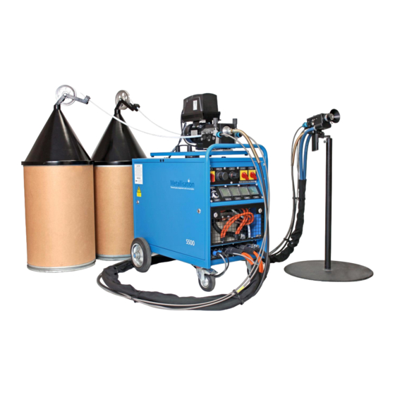
System Configurations Variations of the below standard configurations may be possible. Contact Metallisation to discuss your specific application requirements. Standard Configuration – Push/Pull with wire in Drums Most commonly used for in-house anti-corrosion applications where drums can easily be handled. - Page 16 Extended Configuration – Push/Pull with wire on MIG reels Most commonly used in hard to reach areas such as boilers/vessels where access for the energiser is limited. Hardboard reel variant can also be offered on the trolley. Pistol Extension Energiser Supplies from wire drive to Push/pull drive unit and MIG Supplies...
-
Page 17: Operating The Equipment
SECTION 3 OPERATING THE EQUIPMENT Connecting the System Connecting using a Powered Extension Trolley Preparing to Spray Spraying Shutting Down Remote Pendant Using Optional Arc Extension Closed Loop and Open Loop Modes Page 17 of 48... -
Page 18: Connecting The System
Connecting the System S500-PLC Energiser. Drive Unit Assembly. Power Cable / Air Hose Assembly. Wire Feed Conduits. Flexible Drive Cable. ARC150 Pistol and Tool Case. Remove any packing materials and ensure that all items are present and the equipment has suffered no damage whilst in transit (see conditions of sale). - Page 19 Connecting the System continued… Ensure that power to the Energiser is isolated. Connect the Supplies Pack, comprising Power Cables (A), Motor Drive Cable (B) and Nozzle Air Hose (C) from the Manifold to the appropriate connections on the front of the Energiser.
-
Page 20: Connecting Using A Powered Extension Trolley
Connecting using a Powered Extension Trolley Using a Powered Extension Trolley allows the Energiser to be sited further away from the spray job whilst still maintaining the power, air and control couplings quick release feature. PART NO. DESCRIPTION ARC150-PET ARC150 powered extension trolley for ARC150 system BACK FRONT Page 20 of 48... - Page 21 Connect the system using the powered extension trolley as follows: Ensure that power to the Energiser is isolated. Connect the Extension Supplies Pack, comprising Power Cables, Motor Drive Cable and Nozzle Air Hose to the appropriate connections on the front of the Energiser and connect the Control Cables from the DUA Wire Feed Unit to the Energiser.
-
Page 22: Preparing To Spray
Preparing to Spray If using MIG Dispensers, use the following procedure: Open the Mig Dispenser and if attached, unscrew the retaining nut. Load the Wire for spraying into the Mig Dispenser Reels with the wire feeding from the bottom of the reel. Screw on the retaining nut. - Page 23 Preparing to Spray continued… “CLICK!” 150mm “CLICK!” Turn the energiser on. Wait 10 seconds for the drive unit to power up. Pull the Trigger on the Pistol to drive the wire Connect the Conduits. A “click” will confirm they have attached through the other end of the conduits.
-
Page 24: Spraying
Spraying NB: Before spraying ensure that all the appropriate safety steps have been taken and the necessary eye and ear protection is being used, in accordance with the Risk Assessment. See Section 1 – Safety Precautions and Risk Assessment. It is also important to be familiar with the Shutting Down procedure –... - Page 25 throughputs which in turn will increase the reading on the Ammeter. See Section 3.8 for information on Closed Loop and Open Loop Modes. THE NEXT OPERATION WILL INITIATE SPRAYING 10. Squeeze the trigger on the Pistol handle. 11. When spraying the voltmeter (F) will display the ‘DURING SPRAYING’ figure. 12.
-
Page 26: Shutting Down
Shutting Down 1. Release the Trigger on the Handle (A) to stop spraying. 2. The Pistol will stop spraying but air will continue to pass through the Spray Head and there will be voltage at the terminals and wire. 3. The Voltmeter (B) will once again display the ‘BEFORE SPRAYING’ Voltage. 4. -
Page 27: Using Optional Arc Extension
When using the Remote Pendant the Pistol MUST NOT be handheld. When fitted the Pistol ON / OFF and the trigger are diabled. For information on the installation of the Remote Pendant please refer to DIAG: EN 277 found in the Energiser Maintenance Manual: MAN-ENE-S500(150) General Operation of the system when the Remote Pendant is fitted: –... -
Page 28: Basic Maintenance
SECTION 4 BASIC MAINTENANCE Routine Maintenance CG Spray Head – Checking Contact Tips CG Spray Head – Complete Disassembly CG Spray Head Reassembly Tension Adjustment of Rollers Roller Guide Assembly Maintenance Rear Wire Guides - Checking Supplies & Manifold Maintenance Wire Condition Page 28 of 48... -
Page 29: Routine Maintenance
Routine Maintenance The following table gives a basic routine maintenance schedule for the ARC150 System. NB: Before commencing repairs or maintenance on any part of the System, ensure that the power is isolated. If possible, work should be carried out in a clean environment, if the system has not been used for a period of time it is strongly recommended that all electrical connections are checked before commencing operation. -
Page 30: Cg Spray Head - Checking Contact Tips
CG Spray Head – Checking Contact Tips NOTE: Before attempting to disassemble the Spray Head always ensure that the mains power supply is isolated and the wire has been removed from the pistol. already removed, loosen the Pointed Shroud Screw and remove Shroud pulling forward. - Page 31 Continue to remove the Contact Tips using the following technique: At this point the Spray Head will look as shown and the Remove the Air Concentrator by pulling forward. Contact Tips will be accessible. Using suitable spanner, remove the Contact Tips check for damage and clean / replace as...
-
Page 32: Cg Spray Head - Complete Disassembly
CG Spray Head – Complete Disassembly NOTE: Before attempting to disassemble the Spray Head always ensure that the mains power supply is isolated and the wire has been removed from the pistol. Loosen the Thumb Screw and remove the Hood. Check the If not already removed, loosen the Pointed Shroud Screw ‘O’... - Page 33 Taking care not to drop any of the parts, continue to inspect the Spray Head parts using the following technique: Taking care not to drop any of the Spray Head parts, unscrew and remove the Air Cover. The Air Cover should be easy to unscrew having loosened it whilst attached to the pistol.
-
Page 34: Cg Spray Head Reassembly
CG Spray Head Reassembly Once all Spray Head parts have been cleaned and any damaged parts have been renewed, the Spray Head can be reassembled using the following technique: Press the Transfer Plug into the Contact Tube Support Block until the largest diameter touches the rear of the... - Page 35 Before refitting the Spray Head onto the pistol, ensure that the contact areas on the Terminals and Clamp Pads are clean and undamaged. Poor contact in these areas can cause overheating. Place the Spray Head against the front of the pistol. Ensure the Transfer Plug locates in the Contact Tube Support Block and the Contact Tubes locate in the left and right hand Terminals.
-
Page 36: Tension Adjustment Of Rollers
Tension Adjustment of Rollers It may be necessary from time to time to adjust the tension of the Roller Guides. Correct wire tension is the minimum tension required to satisfactorily feed the wire through the pistol. The need to suddenly apply more tension is usually an indication of another issue such as worn wire guides, incorrectly assembled spray head, excessive drag from the wire dispenser, dirty/worn rollers or worn/damaged/seized pinch roll bearings. -
Page 37: Roller Guide Assembly Maintenance
Roller Guide Assembly Maintenance The Roller Guides will normally only need to be removed to renew if the Roller teeth are found to be broken, worn or choked with debris from the wire Check for excessive spring tension and adjust accordingly (Section 4.5 – Tension Adjustment of Rollers). -
Page 38: Rear Wire Guides - Checking
Rear Wire Guides - Checking The Rear Wire Guides may be removed for cleaning or renewal whenever necessary i.e. when worn. The Power Supply must be isolated and the wire completely removed from the rear of the Pistol. Rear Wire Guide The Rear Wire Guides can then be removed by unscrewing them from the Left and Right Hand Side Plates. -
Page 39: Supplies & Manifold Maintenance
Supplies & Manifold Maintenance In accordance with the Routine Maintenance Schedule – Section 4.1, periodically it is necessary to check all electrical connections at the Supplies. Any loose cables / connections should be tightened. Also, as the supplies will be moved around frequently, all cables and connections should be checked for wear / damage and replaced when necessary. -
Page 40: Wire Condition
The most common solution when debris is a problem is to wet a lint free pad with approximately 5ml of Metallisation Wire Oil and fold it over the wire where it enters the wire conduit. The pad may be held in place with a small spring clip and the pad removed and folded in a different place every hour or so depending on the amount of debris collected. -
Page 41: Fault Finding
SECTION 5 FAULT FINDING Operational Troubleshooting Page 41 of 48... -
Page 42: Operational Troubleshooting
Wire should always pull freely. If it does not and excessive force is needed check / clean / replace the wire conduits as necessary. It is essential that the Metallisation ARC150 Arcspray System is properly maintained and operated. Faults may occur due to incorrect operation, lack of proper maintenance or incorrect component selection. -
Page 43: Illustrated Parts List
SECTION 6 ILLUSTRATED PARTS LIST Main Components CG Spray Head Page 43 of 48... -
Page 44: Main Components
Main Components For general operation only certain components should ever need to be dismantled and / or replaced. Periodically, more detailed maintenance will be required. For a complete Illustrated Parts Listing of the ARC150 Pistol and Energiser please see the relevant Maintenance Manual. 5581 5582 7546... -
Page 45: Cg Spray Head
6.2 CG Spray Head FIG 1 gives an illustrated view of the Spray Head. Table 1 lists the parts that remain the same for all Spray Head configurations. Please note that the Contact Tips vary dependant on the wire being sprayed and the appropriate part numbers are shown in Table 2. 7507 7577 1007... -
Page 46: Information Tables
SECTION 7 INFORMATION TABLES Typical Performance Figures Page 46 of 48... -
Page 47: Typical Performance Figures
Typical Performance Figures THROUGHPUT(KG/HR) COVERAGE MATERIAL WIRE DIAMETER 500A m² /kg/100 Metallisation Wire 2.3mm 2.88 01E Aluminium Metallisation Wire 2.3mm 0.82 02E Zinc Metallisation Wire 21E Zinc/Aluminium 2.3mm 1.00 85/15 Metallisation Wire 2.3mm 3.85 28E Arctec Metallisation Wire 13.6 1.6mm 1.02... - Page 48 Fax: +44 1384 237196 Email: support@metallisation.com The information in this manual was correct at the time of publication; Metallisation disclaims liability for any inaccuracies or omissions that may have occurred. Periodically, changes are made to the information herein, and Metallisation reserve...
Need help?
Do you have a question about the ARC150-2310D and is the answer not in the manual?
Questions and answers