
Related Manuals for Quantum Composers miniSystem Series

Summary of Contents for Quantum Composers miniSystem Series
- Page 1 MINISYSTEM Laser System Operating Manual QUANTUM COMPOSERS, INC PO Box 4248 Bozeman, MT 59772 (406)582-0227 phone (406)582-0237 fax www.quantumcomposers.com MINISYSTEM Manual Version 1.5 Page 1...
-
Page 2: Table Of Contents
Contents INTRODUCTION .............................. 4 Technical Support ................................ 4 Warranty ..................................4 Package Contents ................................ 4 SAFETY ................................5 Laser Safety ..............................6 Safety Issues ..............................7 Electrical Safety ..............................8 Sources of Laser Safety Standards ..........................8 Safety Labels and Locations ............................9 SYSTEM OVERVIEW ............................ - Page 3 General System Commands ............................29 Laser Operation Commands ............................30 Slit Commands ................................31 Illuminator Commands..............................31 Calibration Commands ............................... 32 MAINTENANCE ............................. 33 TROUBLE-SHOOTING ..........................33 No Laser Output ................................. 33 Energy is Low ................................33 SPECIFICATIONS ............................. 34 miniSystem Laser Specifications ..........................
-
Page 4: Introduction
1. Introduction This manual is a reference designed to familiarize you with the Quantum Composers miniSystem series laser system and is arranged so that you can easily find the information you’re looking for. Generally, each topic has its own section and no section assumes that you’ve read anything else in the manual. -
Page 5: Safety
2. Safety This user’s manual contains the technical information needed to properly install, operate, and maintain the miniSystem laser system. It provides instructions for setup and installation, operation, service, preventive maintenance, and troubleshooting (fault-isolation). The laser system consists of one major subassembly: 1. -
Page 6: Laser Safety
CAUTION: Risk of Electric Shock. ATTENTION: Risque d’éléctrocution. ACHTUNG!: Gefahr durch Stromschlag. ATTENZIONE: Rischio di shock elettrico. ADVERTENCIA: Riesgo de choque eléctrico CAUTION: Risk of exposure to hazardous laser radiation. ATTENTION: Risque d’exposition à un rayonnement laser dangereux. ACHTUNG!: Gefahr durch gefährliche Laserstrahlung. ATTENZIONE: Rischio di esposizione a pericolose radiazioni laser. -
Page 7: Safety Issues
Maintain a high ambient light level in the laser operation area so the eye pupil remains constricted, thus reducing the possibility of hazardous exposure. Post prominent warning signs near the laser operation area. Provide enclosures for the beam path whenever possible. ... -
Page 8: Electrical Safety
If possible, familiarize yourself with the equipment being tested and the location of its high-voltage points. However, remember that high voltage may appear at unexpected points in defective equipment. Do not expose high voltage needlessly. Remove housing and covers only when necessary. -
Page 9: Safety Labels And Locations
Occupational Safety and Health Administration U.S. Department of Labor 200 Constitution Avenue N.W. Washington, DC 20210 USA Phone: (202) 523-8148 “Safety of Laser Products” (EN60825-1:1994) Global Engineering Documents 15 Iverness Way East Englewood, CO 80112-5704 USA Phone: (303) 792-2181 Safety Labels and Locations The following figures show the safety labels, model number, serial number and origination labels, and their locations on the miniSystem Laser System. - Page 10 Figure 4 Cover Exposure Label Figure 5 Non-Interlocked Cover Label Figure 6 Model, Serial, and Origination Label Figure 7 MINISYSTEM Safety Labels Front MINISYSTEM Manual Version 1.5 Page 10...
- Page 11 Figure 8 MINISYSTEM Safety Labels Back MINISYSTEM Manual Version 1.5 Page 11...
-
Page 12: System Overview
3. System Overview MINISYSTEM Block Diagram Figure 9 shows the laser system block diagram, which consists of the Jewel Laser, the laser optic modules, and the System Power Supply. Figure 9 System Block Diagram Laser System Power Supply The portable power supply contains an AC/DC converter to supply the needed voltage for the miniSystem system from one AC supply. -
Page 13: Description Of Payload
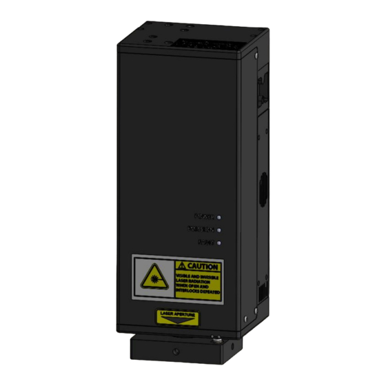
Figure 10 Power Supply Description of Payload The miniSystem payload contains multi-wavelength laser optics assemblies for beam control, the miniJewel laser head, a beam combining assembly, and the payload system controller. The laser head includes a 1064nm laser with an attached nonlinear module which converts the 1064nm (IR) laser output to 532nm (GRN), 355nm (UV), or 266nm (DUV). - Page 14 Figure 11 Laser Optical Assembly The resonator is a diode pumped laser with an output wavelength of 1064 nm and nonlinear module to perform harmonic generation to produce a few key wavelengths. Resonator mirrors are hard-mounted to the machined resonator bench, which results in an extremely stiff, rugged resonator which is much less sensitive to misalignment then standard laser resonators.
- Page 15 The laser beam then illuminates the optional XY Theta aperture. The XY Theta aperture forms a rectangular shape and each axis is independently controlled. The rectangular shape can be rotated ±45 degrees from horizontal. The Aperture Backlight shines through the 2 mirror of the Parallel Mirror assembly to illuminate the XY Aperture.
-
Page 16: Installation
4. Installation Unpacking the Laser System The laser system has been carefully packaged for shipment. If the container arrives damaged in any way, please contact the shipper's agent to be present for the unpacking. Inspect each unit as it is unpacked, looking for dents, scratches, or other damage. If damage is evident, immediately file a claim against the carrier and notify the manufacturer. -
Page 17: System Installation
System Installation CAUTION: When utilizing the Remote Interlock capability, use an isolated contact closure such as a relay to avoid generating undesirable ground loops. CAUTION: Ensure that the system is connected to the proper Mains voltage. The voltage rating is marked on the Laser System Power Supply. Operating the system at the incorrect voltage may result in damage to the unit. -
Page 18: Laser System Setup
Laser System Setup 1. Attach USB cable to laser system payload and connect the opposite end to a computer or optional SMART controller. The connections are specific so that connectors cannot be miss-matched. 2. Connect the power barrel connector to the laser system payload. 3. -
Page 19: System Indicators
(1040.10(f)(4)). The miniSystem size prevents the implementation of a standard key operation so a password method has been implemented. When using the Quantum Composers LSxxx application or the SMART controller, the user will be prompted to enter either the master or user password before allowing the laser to be enabled and fired. -
Page 20: Laser Operation
NOTE: Laser harmonic crystals must warm up. This can take 10 minutes before stable output energy can be realized. Operation Guidelines CAUTION: Below is a list of guidelines, which apply to all Quantum Composers’ laser systems. These guidelines should be followed whenever possible to avoid laser damage. -
Page 21: Smart Controller
SMART Controller The SMART controller is a standalone remote box that allows manual control of the system. This method is usually preferred when the system is used on a microscope and used for manual repairs. The SMART controller is connected to the miniSystem via a standard USB cable. Please refer to the SMART Controller Manual for more information on its operation. -
Page 22: Laser Control
Figure 14 LS6xx Software Application Opening Screen Laser Control 1. Pulse Mode – Options are continuous, single shot or burst. a. Continuous mode – The laser will fire continuously from the time the Fire button is pressed until the Stop button is pressed. The pulses per second are controlled with the Rep Rate parameter. -
Page 23: Cut Size
a. High Power – The laser energy will range from 0 to the value set with the calibration command. (See ECS in the command section). b. Low Power – The laser energy will range from 0 to 25% of the value set with the calibration command. -
Page 24: Usb Communications
7. USB Communications Personal Computer to Laser System Communication The MINISYSTEM has a standard USB port. All menu settings can be set and retrieved over the computer interface using a simple command language. The command set is structured to be consistent with the Standard Commands for Programmable Instruments (SCPI). -
Page 25: Device Address
Device Address Address Device Laser Controller Command Types There are two types of commands -- those that set a value or initiate an action (control commands), and those that request information (query commands). Each device must respond in the proper manner to each type of command. Control Commands A device must always parse a control command and return a response immediately. -
Page 26: Query Commands
Query Commands Query commands return a value to the PC as soon as the command is parsed and executed. The value returned will depend on the command. The response is always terminated with a “<CR><LF>”. If a query command is not recognized by the device, then a "?1" is returned. Error Codes Command not recognized. - Page 27 Command to send: ;LC:SW 4<CR> Response: OK<CR> Description: Sets the active wavelength to DUV (266nm). Command to send: ;LC:ED 4,1,500<CR> Response: OK<CR> Description: Sets the wavelength to DUV (266nm), the level to high mode and the percentage to 50%. Command to send: ;LC:SP 10,1000,1000<CR>...
- Page 28 To recall a saved recipe, use the following command: Command to send: ;LC:LR 2<CR> Response: OK<CR> Description: Loads the configurations settings from storage location #2. Once a recipe is recalled, the only commands that need to be sent are the enable laser (EN) and the fire laser (FL).
-
Page 29: General System Commands
General System Commands Done Firing. This query will send back a “done” response once the DONE? laser is finished firing. An example situation would be waiting for a burst to finish. Once the burst is done, the “done” response will be sent back. -
Page 30: Laser Operation Commands
UP # User Password. This command can be used to query or change the user password to allow enabling and firing of the laser. The Master code must be entered prior to using this command. See the PW command. Version Number – Query Only. Returns the current LSC version number in the format of major.minor.release. -
Page 31: Slit Commands
Laser Setup. This is a combined command to adjust multiple #,#,###,###,###,### system parameters at once instead of issuing multiple commands. First Parameter = Select wavelength (1 = IR, 2 = GRN, 3 = UV, 4 = DUV), Second Parameter = Selects High (1) or Low (0) mode, Third Parameter = Set Energy Density (0 –... -
Page 32: Calibration Commands
IL #,#### Illuminator level. First parameter is the illuminator channel. 0 = Coax(if installed), 1 = Slit backlight. The second parameter is the intensity level 0 to 1000. Status returns level for both illuminators. Calibration Commands ECS #,# Energy Calibration Setup. Sets up the system for energy calibration. -
Page 33: Maintenance
8. Maintenance The miniSystem Laser System is designed to be maintenance free and should provide many hours of operation before any maintenance is required. In the event that the system is not performing to specification, please contact the factory for service. 9. -
Page 34: Specifications
10. Specifications miniSystem Laser Specification Notes Specifications miniJewel Laser Sealed, conductively cooled resonator integrated with drive and control electronics. Wavelength Two wavelengths Beam selection and energy control using (1064/532, 532/355, or filter wheel and dual wavelength attenuator. 532/266) Rep Rate 1-30 Hz 30-50Hz Limited* Energy per Pulse (Typical) -
Page 35: Theta Slit
Specification Notes Theta Slit Rotation Range -45 to +45 degrees Accuracy ± 1.0 degree Resolution 0.5 degrees ≤ 1.0 s Tact Time Full range of travel. ≤ 6.0 s Initialization From power-up. Specification Notes Filter Wheel Positions ≤ 1.0 s Full range of travel. -
Page 36: Customer Service
During the one year warranty period, we will repair or replace, at our option, any defective products or parts at no additional charge, provided that the product is returned, shipping prepaid, to Quantum Composers. All replaced parts and products become the property of the manufacturer.
Need help?
Do you have a question about the miniSystem Series and is the answer not in the manual?
Questions and answers