Table of Contents
Advertisement
Quick Links
Advertisement
Table of Contents

Related Manuals for Utax DP 770


Summary of Contents for Utax DP 770
- Page 1 Service Manual Document Processor Rev.: .0 Date: -0 -201 3NVSM06...
- Page 2 Service Manual Document Processor Rev.: .0 Date: -0 -201 3NVSM06...
- Page 3 CAUTION RISK OF EXPLOSION IF BATTERY IS REPLACED BY AN INCORRECT TYPE. DISPOSE OF USED BATTERIES ACCORDING TO THE INSTRUCTIONS. It may be illegal to dispose of this battery into the municipal waste stream. Check with your local solid waste officials for details in your area for proper disposal. ATTENTION IL Y A UN RISQUE D’EXPLOSION SI LA BATTERIE EST REMPLACEE PAR UN MODELE DE TYPE INCORRECT.
- Page 4 Revision history Revision Date Replaced pages Remarks 6 April 2011 Safety precautions, 1-3-45, 1-6-1, 2-1-2, 2-1-6, 2-4-4 - 4 June 2012 1-3-1, 1-3-2, 13-10 to 16, 1-3-18, 1-3-19, 1-3-21 to 29, 1-3-32 to 39, 1-3-41 to 44, 1-4-3, 1-4-4, 2-4-1, Address...
- Page 5 This page is intentionally left blank.
- Page 6 Safety precautions This booklet provides safety warnings and precautions for our service personnel to ensure the safety of their customers, their machines as well as themselves during maintenance activities. Service personnel are advised to read this booklet carefully to familiarize themselves with the warnings and precautions described here before engaging in maintenance activities.
- Page 7 Safety warnings and precautions Various symbols are used to protect our service personnel and customers from physical danger and to prevent damage to their property. These symbols are described below: DANGER: High risk of serious bodily injury or death may result from insufficient attention to or incorrect compliance with warning messages using this symbol.
- Page 8 1. Installation Precautions WARNING • Do not use a power supply with a voltage other than that specified. Avoid multiple connections to one outlet: they may cause fire or electric shock. When using an extension cable, always check that it is adequate for the rated current...................... •...
- Page 9 2. Precautions for Maintenance WARNING • Always remove the power plug from the wall outlet before starting machine disassembly....• Always follow the procedures for maintenance described in the service manual and other related brochures............................• Under no circumstances attempt to bypass or disable safety features including safety mechanisms and protective circuits.
- Page 10 • Do not remove the ozone filter, if any, from the copier except for routine replacement....... • Do not pull on the AC power cord or connector wires on high-voltage components when removing them; always hold the plug itself......................•...
- Page 11 This page is intentionally left blank.
-
Page 12: Table Of Contents
CONTENTS 1-1 Specifications 1-1-1 Specifications ........................1-1-1 1-1-2 Parts names .......................... 1-1-2 1-1-3 Machine cross section ......................1-1-3 1-2 Installation 1-2-1 Installation environment......................1-2-1 1-2-2 Unpacking..........................1-2-2 (1) Unpacking......................... 1-2-2 (2) Remove the tapes and pad ....................1-2-3 1-3 Maintenance Mode 1-3-1 Maintenance mode ........................ - Page 13 2-2 Electrical Parts Layout 2-2-1 Electrical parts layout ......................2-2-1 (1) PWBs..........................2-2-1 (2) Switches and sensors....................... 2-2-2 (3) Motors..........................2-2-3 (4) Others..........................2-2-4 2-3 Operation of the PWBs 2-3-1 DP main PWB........................2-3-1 2-4 Appendixes 2-4-1 Appendixes ..........................2-4-1 (1) List of maintenance parts ....................
-
Page 14: Specifications
1-1 Specifications 1-1-1 Specifications Item Specifications Automatic feed Original feed method Sheet originals Supported original types Maximum: A3/Ledger Original sizes Minimum : A5R/StatementR Simplex: 45 to 160 g/m Original weights Duplex : 50 to 120 g/m 100 sheets (50 to 80 g/m ) or less Loading capacity Mixed original sizes (auto selection) 30sheets (50 to 80 g/m... -
Page 15: Parts Names
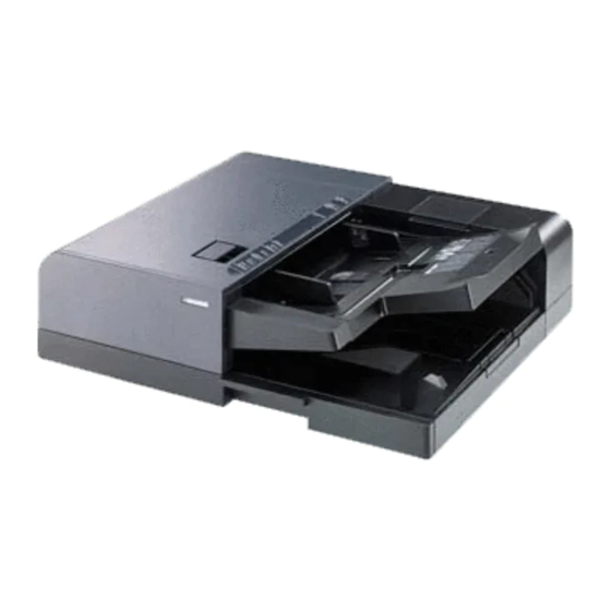
1-1-2 Parts names Figure 1-1-1 1. Original tray 5. DP top cover 2. Original width guides 6. DP switchback tray 3. Original eject table 7. Cleaning cloth compartment 4. Original stopper 1-1-2... -
Page 16: Machine Cross Section
1-1-3 Machine cross section Original Path Figure 1-1-2 Machine cross section 1. Original feed section 2. Original conveying section 3. Original switchback/eject section 1-1-3... - Page 17 This page is intentionally left blank. 1-1-4...
-
Page 18: Installation Environment
1-2 Installation 1-2-1 Installation environment Installation location (Be based on the machine establishment place.) Avoid direct sunlight or bright lighting. Ensure that the photoconductor will not be exposed to direct sunlight or other strong light when removing paper jams. Avoid locations subject to high temperature and high humidity or low temperature and low humidity; an abrupt change in the environmental temperature;... -
Page 19: Unpacking
1-2-2 Unpacking (1) Unpacking Figure 1-2-1 Unpacking 1. Document processor 9. Rear top pad 17. Angle control fitting 2. Plastic sheet 10. Cleaning cloth 18. Fixing fittings 3. Inner frame 11. Plastic bag 19. Plastic bag 4. Outer case 12. Installation guide 20. -
Page 20: Remove The Tapes And Pad
(2) Remove the tapes and pad Procedure Tape 1. Remove four tapes. Tape Tape Tape Figure 1-2-2 2. Open the DP top cover and original DP top cover width guides. Original width guide 3. Remove the pad. Original width guide Figure 1-2-3 1-2-3... - Page 21 This page is intentionally left blank. 1-2-4...
-
Page 22: Maintenance Mode
3NV-2 1-3 Maintenance Mode 1-3-1 Maintenance mode The machine is equipped with a maintenance function which can be used to maintain and service the machine. (1) Executing a maintenance item Start Enter “10871087” using Maintenance mode is entered. the numeric keys. Enter the maintenance item number using the cursor up/down keys The maintenance item is selected. -
Page 23: Maintenance Mode Item List
3NV-2 (2) Maintenance mode item list Item Section Content of maintenance item Initial setting General U000 Outputting an own-status report U001 Exiting the maintenance mode Optical U061 Checking the operation of the exposure lamp U068 Adjusting the scanning position for originals from the DP U070 Adjusting the DP magnification 0/0/0 U071 Adjusting the DP scanning timing... -
Page 24: Contents Of Maintenance Mode Items
(3) Contents of maintenance mode items Item No. Description U000 Outputting an own-status report Description Outputs lists of the current settings of the maintenance items, and paper jam and service call occurrences. Outputs the event log or service status page. Also sends output data to the USB memory. - Page 25 Item No. Description U000 Method: Send to the USB memory 1. Press the power key on the operation panel, and after verifying the main power indicator has gone off, switch off the main power switch. 2. Insert USB memory in USB memory slot. 3.
- Page 26 Item No. Description U000 Event log Event Log 27/Oct/2010 08:40 Firmware version 2LC_2000.000.000 2010.10.27 [XXXXXXXX] [XXXXXXXX] [XXXXXXXX] [XXXXXXXX] (12) Paper Jam Log Counter Log Count. Event Descriprions J0000: J0041: C0000: T00: 9999999 0501.01.08.01.01 J0001: J0042: C0001: T01: 8888888 4002.01.08.01.01 J0002: J0043: C0002: T02:...
- Page 27 Item No. Description U000 Detail of event log Items Description Controller BROM version Operation panel mask version Machine serial number Paper Jam Count. Event Remembers 1 to 16 of The total page count Log code (hexadeci- occurrence. If the occur- at the time of the mal, 5 categories) rence of the previous...
- Page 28 Item No. Description U000 Items Description Paper Jam (d) Detail of paper type (Hexadecimal) cont. 01: Plain 0A: Color 15: Custom 1 02: Transparency 0B: Pre punched 16: Custom 2 03: Preprinted 0C: Envelope 17: Custom 3 04: Labels 0D: Cardstock 18: Custom 4 05: Bond 0E: Coated...
- Page 29 Item No. Description U000 Items Description Service Call Count. Service Code Remembers 1 to 8 The total page Self diagnostic error code of occurrence of self count at the time of (See page 1-4-3) diagnostics error. If the self diagnostics the occurrence of error.
- Page 30 Item No. Description U000 Items Description (12) Counter Log (f) Paper jam (g) Self diagnostic (h) Maintenance item error replacing Comprised of Indicates the log Indicates the log Indicates the log coun- three log coun- counter of paper counter of self diag- ter depending on the ters including jams depending on...
- Page 31 3NV-2 Item No. Description U000 Service status page (1) Service Status Page 27/10/2010 12:00 Firmware version 2LC_2000.000.000 2010.10.27 [XXXXXXXX] [XXXXXXXX] [XXXXXXXX] Controller Information (30) FAX Information Slot1/Slot2 (31) Rings (Normal) Memory status (32) Rings (FAX/TEL) Total Size 2.0 GB (33) Rings (TAD) (34) Option DIMM Size...
- Page 32 3NV-2 Item No. Description U000 Service status page (2) Service Status Page 27/10/2010 12:00 Firmware version 2LC_2000.000.000 2010.10.27 [XXXXXXXX] [XXXXXXXX] [XXXXXXXX] Engine Information Send Information (40) (44) NVRAM Version _1F31225_1F31225 Date and Time 10/10/27 (41) (45) Scanner Version 2LC_1200.001.089 Address (42) FAX Slot1 FAX BOOT Version...
- Page 33 3NV-2 Item No. Description U000 Detail of service status page Description Supplement Firmware version System date Engine soft version Engine boot version Operation panel mask version Machine serial number Total memory size Local time zone Report output date Day/Month/Year hour:minute (10) NTP server name (11)
- Page 34 3NV-2 Item No. Description U000 Description Supplement (28) Cleared date and output date (29) Coverage on the final output page (30) Fax kit information This item is printed only when the fax kit is installed. (31) Number of rings 0 to 15 (32) Number of rings before auto- 0 to 15...
- Page 35 3NV-2 Item No. Description U000 Description Supplement (44) The last sent date and time (45) Transmission address (46) Destination information (47) Area information (48) Margin settings Top margin/Left margin (49) Margin/Page length/Page width Top margin integer part/Top margin decimal part/ settings Left margin integer part/Left margin decimal part/ Page length integer part/Page length decimal part/...
- Page 36 3NV-2 Item No. Description U000 Description Supplement (65) Media type attributes Weight settings Fuser settings 1 to 28 (Not used: 18, 19, 20) 0: Light 0: High 1: Normal 1 1: Middle 2: Normal 2 2: Low 3: Normal 3 3: Vellum 4: Heavy 1 Duplex settings...
- Page 37 3NV-2 Item No. Description U000 Description Supplement (90) Toner low detection level 0 to 100 (%) (91) Drum serial number Black/Cyan/Magenta/Yellow Code conversion Completion Press the stop key. The screen for selecting a maintenance item No. is displayed. U001 Exiting the maintenance mode Description Exits the maintenance mode and returns to the normal copy mode.
- Page 38 Item No. Description U068 Adjusting the scanning position for originals from the DP Description Adjusts the position for scanning originals from the DP. Performs the test copy at the four scan- ning positions after adjusting. Purpose Used when the image fogging occurs because the scanning position is not proper when the DP is used.
- Page 39 3NV-2 Item No. Description U070 Adjusting the DP magnification Description Adjusts the DP original scanning speed. Purpose Make the adjustment if the magnification is incorrect in the auxiliary scanning direction when the DP is used. Adjustment 1. Press the start key. 2.
- Page 40 3NV-2 Item No. Description U070 Caution Check the copy image after the adjustment. If the image is still incorrect, perform the following adjustments in maintenance mode. U070 U039 Completion Press the stop key. The screen for selecting a maintenance item No. is displayed. 1-3-19...
- Page 41 Item No. Description U071 Adjusting the DP scanning timing Description Adjusts the DP original scanning timing. Purpose Make the adjustment if there is a regular error between the leading or trailing edges of the origi- nal and the copy image when the DP is used. Method 1.
- Page 42 3NV-2 Item No. Description U071 Adjustment: Leading edge registration 1. Change the setting value using the +/- keys or numeric keys. For copy example 1, increase the value. For copy example 2, decrease the value. Increasing the value moves the image forward and decreasing the value moves the image backward.
- Page 43 3NV-2 Item No. Description U072 Adjusting the DP center line Description Adjusts the scanning start position for the DP original. Purpose Make the adjustment if there is a regular error between the centers of the original and the copy image when the DP is used. Adjustment 1.
- Page 44 3NV-2 Item No. Description U073 Checking the scanner operation Description Simulates the scanner operation under the arbitrary conditions. Purpose To check the scanner operation. This is also done to check the accumulation of dust on the slit glass. Method 1. Press the start key. 2.
- Page 45 3NV-2 Item No. Description U073 Method: [Home Position] 1. Select [Home Position]. 2. Press the start key. The mirror frame of the scanner moves to the home position. Method: [Dust Check] 1. Select [Dust Check]. 2. Press the start key. The exposure lamp lights. 3.
- Page 46 3NV-2 Item No. Description U087 Setting DP reading position modification operation Description The presence or absence of dust is determined by comparing the scan data of the original trailing edge and that taken after the original is conveyed past the DP original scanning position. If dust is identified, the DP original scanning position is adjusted for the following originals.
- Page 47 3NV-2 Item No. Description U099 Adjusting original size detection Description Checks the operation of the original size sensor and sets the sensing threshold value. Purpose Modify the threshold of detection if documents are frequently mal-detected in size after scanning a wholly dark document or a document enclosed with dark objects on edges. Method 1.
- Page 48 3NV-2 Item No. Description U099 Setting: [B/W Level1] 1. Select an item to be set. 2. Change the setting value using the +/- keys or numeric keys.l Setting Initial Display Description range setting* Original R1 Original threshold value for color R (near side) 0 to 255 20/50 Original R2...
- Page 49 3NV-2 Item No. Description U203 Checking DP operation Description Simulates the original conveying operation separately in the DP. Purpose To check the DP operation. Method 1. Press the start key. 2. Place an original in the DP if running this simulation with paper. 3.
- Page 50 3NV-2 Item No. Description U243 Checking the operation of the DP motors Description Turns the motors or solenoids in the DP on. Purpose To check the operation of the DP motors and solenoids. Method 1. Press the start key. 2. Select the item to be operated. 3.
- Page 51 Item No. Description U244 Checking the DP switches Description Displays the status of the respective switches in the DP. Purpose To check if respective switches in the DP operate correctly. Method 1. Press the start key. 2. Turn each switch or sensor on and off manually to check the status. When a switch or sensor is detected to be in the ON position, the display for that switch or sensor reverses.
- Page 52 Item No. Description U326 Setting the black line cleaning indication Description Sets whether to display the cleaning guidance when detecting the black line. Purpose Displays the cleaning guidance in order to make the call for service with the black line decrease by the rubbish on the contact glass when scanning from the DP.
- Page 53 3NV-2 Item No. Description U404 Adjusting margins for scanning an original from the DP Description Adjusts margins for scanning the original from the DP. Purpose Make the adjustment if margins are incorrect. Adjustment 1. Press the start key. 2. Press the system menu key. 3.
- Page 54 3NV-2 Item No. Description U411 Adjusting the scanner automatically Description Uses a specified original and automatically adjusts the following items in the scanner and the DP scanning sections. Purpose To perform automatic adjustment of various items in the scanner and the DP scanning sections. Perform adjustments using a new test chart (chart 1) when replacing ISC PWB, LED lamp PWB, ISU or DP main PWB.
- Page 55 3NV-2 Item No. Description U411 Method: Table (Chart1) To manually enter the target value 1. Enter the target values which are shown on the specified original (P/N: 7505000005) execut- ing maintenance item U425. 2. Set a specified original (P/N: 7505000005) on the platen. 3.
- Page 56 3NV-2 Item No. Description U411 To automatically enter the target value 1. Enter the value for [Adjust Original] using maintenance item U425. 2. Set a specified original (P/N: 7505000005)(front face) in the DP. 3. Enter maintenance item U411. 4. Select [Target]. 5.
- Page 57 3NV-2 Item No. Description U411 Method: DP Face Up (Chart2) 1. Enter the target values which are shown on the specified original (P/N: 302AC68243) execut- ing maintenance item U425. 2. Set a specified original (P/N: 302AC68243) in the DP. * : Cut the trailing edge of the original. 3/16”...
- Page 58 3NV-2 Item No. Description U411 Method: [DP Auto Adj] 1. Load A4/letter paper. 2. Press the start key to output the original for adjustment. 3. Set the output the original for adjustment and press the start key. 4. Set the output the original for adjustment on the DP face up. 5.
- Page 59 3NV-2 Item No. Description U411 Error Codes Codes Description DP uxiliary scanning direction skew error Maintenance request error Main scanning direction center line error DP main scanning direction skew error Main scanning direction magnification error Service call error DP paper misfeed error PWB replacement error Original error Input gamma adjustment original error...
- Page 60 3NV-2 Item No. Description U425 Setting the target Description Enters the lab values that is indicated on the chart (Chart 1: 7505000005/ Chart 2: 302FZ56990) used for adjustment. Purpose Performs data input in order to correct for differences in originals during automatic adjustment. Method 1.
- Page 61 Item No. Description U425 Setting: [Adjust Original] 1. Measure the distance from the leading edge to the top of black belt 1 of the original at A, B and C. Measurement procedure 1) Measure the distance from the leading edge to the top of black belt 1 of the original at A (30 mm from the left edge), B (148.5 mm from the left edge) and C (267 mm from the left edge), respectively.
- Page 62 3NV-2 Item No. Description U425 Method 1. Press the start key. 2. Select the chart for using. Display Description Entering the target values of the chart (P/N: 302FZ56990) used for adjustment Entering the measurement value of the chart (P/N: 302AC68243) used for adjustment Method 1.
- Page 63 3NV-2 Item No. Description U425 Setting: [Adjust Original] 1. Measure the distance from the left edge to the black belt (a) of the original at A, B and C. Measurement procedure 1) Measure the distance from the edge to the black belt (a) of the original at A (30 mm from the leading edge), B (148.5 mm from the leading edge) and C (267 mm from the leading edge), respectively.
- Page 64 3NV-2 Item No. Description U425 Setting: [DP] 1. Measure the distance from the leading edge to the black belt (inside) of the original at A. 2. Enter the measured value using the +/- keys in [Lead]. 3. Measure the distance from the left edge to the black belt (inside) of the original at B. 4.
- Page 65 3NV-2 Item No. Description U905 Checking counts by optional devices Description Displays the counts of document processor or 1000/4000-sheet document finisher. Purpose To check the use of document processor or 1000/4000-sheet document finisher. Method 1. Press the start key. 2. Select the device to be checked. The count of the selected device is displayed. Display Description Counts of document processor...
- Page 66 3NV-1 Item No. Description U942 Setting of deflection for feeding from DP Description Adjusts the deflection generated when the document processor is used. Purpose Use this mode if an original non-feed jam, oblique feed or wrinkling of original occurs when the document processor is used.
- Page 67 This page is intentionally left blank. 1-3-46...
-
Page 68: Original Misfeed Detection
1-4 Troubleshooting 1-4-1 Original misfeed detection (1) Original misfeed indication When an original jams, the machine immediately stops operation and a message is shown on the machine operation panel. To remove the jammed original, open the DP top cover or switchback unit. Paper misfeed detection can be reset by opening and closing the respective covers to turn safety switch off and on. - Page 69 Code Contents Conditions No original feed DP feed sensor (DPFS) does not turn on within specified time 9000 during the first sheet feeding (Retry 5 times). DP original conveying jam DP timing sensor (DPTS) turns off within the specified time since 9001 the sensor turns on.
-
Page 70: Self-Diagnosis
3NV-2 1-4-2 Self-diagnosis (1) Self-diagnostic function This unit is equipped with a self-diagnostic function. When a problem is detected, copying is disabled and the problem displayed as a code consisting of C followed by a number, indicating the nature of the problem. A message is also displayed requesting the user to call for service. - Page 71 3NV-2 Check procedures Code Contents Causes corrective measures Defective DP Replace the DP main PWB and check 9060 DP EEPROM error Mismatch of reading data from two main PWB. for correct operation. locations occurs 3 times succes- Device damage Contact the Service Administrative Divi- sively.
-
Page 72: Electrical Problems
1-4-3 Electrical problems Troubleshooting to each failure must be made in the order of the numbered symptoms. Problem Causes Check procedures / corrective measures Reinsert the connector. Also check for continuity within the 1. Defective connector The LED lamp cable or poor con- connector cable. - Page 73 Problem Causes Check procedures / corrective measures Reinsert the connector. Also check for continuity within the 1. Defective connector DP switchback cable or poor con- connector cable. If none, replace the cable. tact in the connector. motor does not DP switchback motor and DP main PWB (YC14) operate.
- Page 74 Problem Causes Check procedures / corrective measures (10) Reinsert the connector. Also check for continuity within the 1. Defective connector A message indicat- cable or poor con- connector cable. If none, replace the cable. tact in the connector. ing the cover is DP interlock switch and DP main PWB (YC6) open is displayed Replace the DP interlock switch.
-
Page 75: Mechanical Problems
1-4-4 Mechanical problems Problem Causes / check procedures Corrective measures Check if the surfaces of the following pul- Clean with isopropyl alcohol. No primary original leys are dirty with paper powder. feed. DP forwarding pulley DP feed belt Check if the following pulleys is Check visually and replace any deformed. -
Page 76: Precautions For Assembly And Disassembly
1-5 Assembly and Disassembly 1-5-1 Precautions for assembly and disassembly (1) Precautions Before starting disassembly, press the Power key on the operation panel to turn power off. Make sure that the Power indicator and the Memory indicator are off before turning off the main power switch. And then unplug the power cable from the wall outlet. -
Page 77: Assembly And Disassembly
1-5-2 Assembly and disassembly (1) Detaching and refitting the DP original feed belt and DP forwarding pulley Follow the procedure below to replace the DP original feed belt and DP forwarding pulley. Procedure 1. Open the DP top cover. DP feed DP top cover 2. - Page 78 DP feed belt unit 4. Remove the DP feed belt unit from the inserted parts of the DP feed unit. DP feed unit Figure 1-5-3 5. Remove two stop rings from the DP feed belt shaft 6. Remove the pulley, pin and DP feed holder from the shorter shaft side.
- Page 79 DP feed belt shaft B 8. Remove the DP feed belt shaft B from the DP feed belt unit. 9. Remove the DP feed collar B and DP DP feed collar B feed belt from DP feed belt shaft B. DP feed belt unit DP original feed belt Figure 1-5-5...
-
Page 80: Detaching And Refitting The Dp Separation Pulley
(2) Detaching and refitting the DP separation pulley Follow the procedure below to replace the DP separation pulley. DP upper Procedure DP top cover 1. Open the DP top cover. shift guide 2. Open the DP upper shift guide. 3. Remove two screws and then remove Screw the DP lower feed guide. -
Page 81: Image Adjustment
1-5-3 Image adjustment (1) Adjusting the angle of leading edge Perform the following adjustment if the leading edge of the copy image is laterally skewed. Procedure 3mm/4mm 3mm/4mm 1. Place an original on the DP and press the start key to make a test copy. 2. - Page 82 4. Turn adjusting screw at the rear side of the right hinge to adjust the DP position. For copy example 1: Turn the adjusting screw counterclockwise and move the DP to the inner side. For copy example 2: Turn the adjusting screw clockwise and move the DP to the front side.
-
Page 83: Adjusting The Angle Of Trailing Edge
(2) Adjusting the angle of trailing edge Perform the following adjustment if the trailing edge of the copy image is laterally skewed. Procedure 1. Place an original on the DP and press the start key to make a test copy. 2. - Page 84 5. Adjust the height of DP. Loosen the nut. For copy example 1: Loosen the adjust- ing screw. For copy example 2: Tighten the adjust- ing screw. Amount of change per scale: Approx. 0.5 mm Retighten the nut. 6. Refit the DP rear cover. Adjuting screw Scale Figure 1-5-15...
- Page 85 This page is intentionally left blank. 1-5-10...
-
Page 86: Remarks On Dp Main Pwb Replacement
3NV-1 1-6 Requirements on PWB Replacement 1-6-1 Remarks on DP main PWB replacement When replacing the DP main PWB, remove the EEPROM (YS1) from the DP main PWB that has been removed and then reattach it to the new DP main PWB. EEPROM Figure 1-6-1 DP main PWB When the DP main PWB is replaced with a new one, carry out the following procedure. - Page 87 This page is intentionally left blank. 1-6-2...
-
Page 88: Original Feed Section
2-1 Mechanical Construction 2-1-1 Original feed section The original feed section consists of the parts shown in figure. An original placed on the original table is con- veyed to the original conveying section. Original is fed by the rotation of the DP forwarding pulley and DP orig- inal feed belt. - Page 89 3NV-1 DPLS1 DPLS2 DPOS DPFS DPOFM DPOWSW DPLM DPMPWB Figure 2-1-2 Original feed section block diagram 2-1-2...
-
Page 90: Original Conveying Section
2-1-2 Original conveying section The original conveying section consists of the parts shown in figure. A conveyed original is scanned by the optical section (CCD) of machine when it passes through the slit glass of machine. Figure 2-1-3 Original conveying section 1. - Page 91 RGST_SW YC4-A8 DPRS FEED_2B,2A,1A,1B YC5-1,2,3,4 DPOFM CNVY_2B,2A,1B,1A DPOCM YC14-1,2,3,4 CCD _TMG_SW DPTS YC4-B6 DPMPWB Figure 2-1-4 Original conveying section block diagram 2-1-4...
-
Page 92: Original Switchback/Eject Sections
2-1-3 Original switchback/eject sections The original switchback/eject sections consists of the parts shown in figure. An original of which scanning is complete is ejected to the original eject table by the DP eject roller. In the case of duplex switchback scanning, an original is conveyed temporarily to the DP switchback tray and conveyed again to the original conveying section by the DP switchback roller. - Page 93 3NV-1 DPPSOL DPSBS DPSBM DPES DPFSSOL DPMPWB Figure 2-1-6 Original switchback/eject sections block diagram 2-1-6...
-
Page 94: Reverse Duplex Scanning Operation
(1) Reverse duplex scanning operation The first side of original is scanned at the slit glass (machine main body). Slit glass: first side scanning Conveyed to the DP switchback tray by the DP switchback feedshift DP switchback tray guide. DP switchback feedshift guide The original is reversed by the DP switchback roller. - Page 95 This page is intentionally left blank. 2-1-8...
-
Page 96: Electrical Parts Layout
2-2 Electrical Parts Layout 2-2-1 Electrical parts layout (1) PWBs Machine front Machine inside Machine rear Figure 2-2-1 PWBs 1. DP main PWB (DPMPWB) ....Controls electrical components. 2. DP LED PWB (DPLPWB) ..... Indicates presence of originals or an original jam. 2-2-1... -
Page 97: Switches And Sensors
(2) Switches and sensors Machine front Machine inside Machine rear Figure 2-2-2 Switches and sensors 1. DP open/close switch (DPOCSW) ..Detects the opening/closing of the DP. 2. DP interlock switch (DPILSW) ....Breaks the safety circuit when the document processor is opened;... -
Page 98: Motors
(3) Motors Machine front Machine inside Machine rear Figure 2-2-3 Motors 1. DP feed motor (DPOFM) ...... Drives the original feeding section. 2. DP conveying motor (DPOCM)..... Drives the original conveying section. 3. DP switchback motor (DPSBM) .... Drives the switchback roller. 4. -
Page 99: Others
(4) Others Machine front Machine inside Machine rear Figure 2-2-4 Others 1. DP switchback feedshift solenoid (DPFSSOL) ..........Operates the switchback feedshift guide. 2. DP switchback pressure solenoid (DPPSOL) ..........Operates the switchback pulley. 2-2-4... -
Page 100: Dp Main Pwb
2-3 Operation of the PWBs 2-3-1 DP main PWB YC14 Figure 2-3-1 DP main PWB silk-screen diagram 2-3-1... - Page 101 Connector Signal Voltage Description Connected to ENG_PAGES 0/3.3 V DC Pageset signal ISCPWB. ENG_RDY 0/3.3 V DC Ready signal ENG_SEL 0/3.3 V DC Select signal ENG_CLK 0/3.3 V DC(pulse) Clock signal ENG_SI 0/3.3 V DC(pulse) Serial communication data signal ENG_SO 0/3.3 V DC(pulse) Serial communication data signal DP_OPEN 0/3.3 V DC...
- Page 102 Connector Signal Voltage Description ANODE 3.3 V DC 3.3 V DC power output to DPLS1 YC4_A Connected to Ground DP lift sensor LF_UPSW 0/3.3 V DC DPLS1: On/Off 1, DP feed Ground sensor, DP registration FD_SW 0/3.3 V DC DPFS: On/Off sensor, DP 3.3V 3.3 V DC...
- Page 103 Connector Signal Voltage Description LIFT3_OUT2 0/24 V DC (pulse) DPLM drive control signal Connected to LIFT1_OUT2 0/24 V DC (pulse) DPLM drive control signal DP feed motor, DP lift LIFT2_OUT1 0/24 V DC (pulse) DPLM drive control signal motor. LIFT4_OUT1 0/24 V DC (pulse) DPLM drive control signal 24 V DC 24 V DC power output to DPILSW...
-
Page 104: Appendixes
3NV-2 2-4 Appendixes 2-4-1 Appendixes (1) List of maintenance parts Maintenance part name Alternative Part No. part No. Name used in service manual Name used in parts list BELT PF 303LL07490 3LL07490 DP paper feed belt PULLEY LF 303M407480 3M407480 DP forwarding pulley PULLEY SEPARATION 303LL07190... -
Page 105: Periodic Maintenance Procedures
(2) Periodic maintenance procedures 300K/600K/ Maintenance User Section Points and cautions Page part/location call 900K/1200K Test copy Perform at the maxi- Test Test and test mum copy size copy copy Maintenance User 300K/600K/ Section Points and cautions Page part/location call 900K/1200K Original DP paper feed belt... - Page 106 Maintenance User 300K/600K/ Section Points and cautions Page part/location call 900K/1200K Original DP original length Clean Clean Air blow or clean with a dry cloth. table switch Maintenance User 300K/600K/ Section Points and cautions Page part/location call 900K/1200K Covers Covers Clean Clean Clean with alcohol.
-
Page 107: Wiring Diagram
3NV-1 (3) Wiring diagram 2-4-4...
Need help?
Do you have a question about the DP 770 and is the answer not in the manual?
Questions and answers