Advertisement
Quick Links
■
SPECIFICATIONS
Sampling frequency:
Frequency response:
Signal to noise ratio:
Wow and flutter:
Power supply:
Current consumption:
Weight:
Specification and design are subject to change without
※
notice for further improvement.
■
COMPONENTS
PN-2144A-A/D-A
Main unit
Lock pin
Lock pin
PP-2144H-A/B
Main unit
Lock pin
Lock pin
■
NOTE
We cannot supply PWB with component parts in principle.
When a circuit on PWB has failure , please repair it by
component parts base. Parts which are not mentioned in
service manual are not supplied.
Clarion Co., Ltd.
Export Division - 22-3, Shibuya 2-chome, Shibuyaku, Tokyo, 150-8335 Japan
Service Dept.- 50 kamitoda,Toda-shi,Saitama,335 Japan Tel: 048-443-1111 FAX:048-433-6996
44.1kHz
5Hz to 20kHz (
1dB)
±
105dB (1kHz) IHF.A
below measurement limits
DC14.4V (10.8V to 15.6V)
negative ground
Less than 1A
3.8lb. (1.7kg)
−−−−−
331-2241-00
331-2241-10
−−−−−
331-2241-00
331-2241-10
Service Manual
NISSAN Automobile Genuine
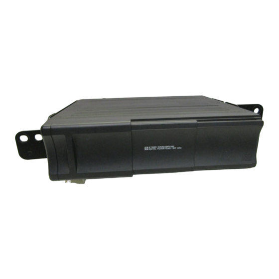
6 DISC COMPACT CHANGER
PN-2144A-A
Model
(Genuine N0. 28184-4H000)
PN-2144D-A
Model
(Genuine N0. 28184-2Y000)
PP-2144H-A
Model
(Genuine N0. 28148-VB000)
PP-2144H-B
Model
(Genuine N0. 28148-VB700)
To engineers in charge of repair
■
or inspection of our products.
Before repair or inspection, make sure to follow
the instructions so that customers and Engineers
in charge of repair or inspection can avoid suf-
fering any risk or injury.
1. Use specified parts.
The system uses parts with special safety features
against fire and voltage. Use only parts with equivalent
characteristics when replacing them.
The use of unspecified parts shall be regarded as re-
modeling for which we shall not be liable. The onus of
product liability (PL) shall not be our responsibility in
1
cases where an accident or failure is as a result of un-
1
specified parts being used.
1
2. Place the parts and wiring back in their original positions
after replacement or re-wiring.
1
For proper circuit construction, use of insulation tubes,
1
bonding, gaps to PWB, etc, is involved. The wiring con-
1
nection and routing to the PWB are specially planned
using clamps to keep away from heated and high volt-
age parts. Ensure that they are placed back in their origi-
nal positions after repair or inspection.
If extended damage is caused due to negligence during
repair, the legal responsibility shall be with the repairing
company.
- 1 -
Published by Service Dept.
Tel: 03-3400-1121
298-5688-00 Sep.1998 P
Printed in Japan
PN-2144A / D
PP-2144H
Advertisement

Related Manuals for Clarion PN-2144A-A


Summary of Contents for Clarion PN-2144A-A
- Page 1 Clarion Co., Ltd. Published by Service Dept. Export Division - 22-3, Shibuya 2-chome, Shibuyaku, Tokyo, 150-8335 Japan Tel: 03-3400-1121 298-5688-00 Sep.1998 P Service Dept.- 50 kamitoda,Toda-shi,Saitama,335 Japan Tel: 048-443-1111 FAX:048-433-6996 Printed in Japan Service Manual NISSAN Automobile Genuine 6 DISC COMPACT CHANGER...
- Page 2 3. Check for safety after repair. 8. Cautions in checking that the optical pickup lights up. Check that the screws, parts and wires are put back se- The laser is focused on the disc reflection surface through curely in their original position after repair. Ensure for the lens of the optical pickup.
-
Page 3: Parts List
EXTENSION LEAD (WITHOUT COMPONENT) 854-7536-13 EXTENSION LEAD(PP-2144H-B) 310-1620-04 UPPER CASE 331-2288-00 LEAD HOLDER 311-1702-06 LOWER CASE 335-0833-05 LEAD HOLDER 320-0539-11 DUSTPROOF CVR 286-9086-00 SETPLATE(PN-2144A-A) 286-9086-01 SETPLATE(PN-2144D-A) 320-0540-08 DUSTPROOF CVR 286-8964-00 SETPLATE(PP-2144H-A) 286-8964-01 SETPLATE(PP-2144H-B) 370-5672-01 ESCUTCHEON(PN-2144A/D) 370-5672-07 ESCUTCHEON(PP-2144H) 347-5476-00 INSULATOR 371-3852-00... - Page 4 CD mechanism module section PART NO. DESCRIPTION Q'TY PART NO. DESCRIPTION Q'TY 750-3249-00 GAP SPRING-R 966-0455-01 REAR PANEL-ASSY 621-0377-00 V-HELICAL GEAR 966-0460-02 V-CHASSIS-ASSY 621-0378-00 V-GEAR A 966-0461-00 UD-GEAR-P-ASSY 621-0380-01 MAGAZINE RAIL 966-0462-05 MG-LO-P-ASSY-S 629-0061-00 GEAR DAMPER 966-0463-02 UP-PLATE-ASSY-S 714-2006-81 MACHINE SCREW (M2×6) −−−−−...
-
Page 5: Drive Unit
Loading unit section DRIVE UNIT PART NO. DESCRIPTION Q'TY PART NO. DESCRIPTION Q'TY 966-0457-03 L-CHASSIS-ASSY 621-0386-01 CAM GEAR 966-0458-01 LOCK-ARM-ASSY 621-0387-01 HOLDER-G-RAIL-L 966-0464-00 CLAMP-SE-ASSY 621-0388-01 HOLDER-G-RAIL-R 966-0467-00 PUSH PLATE-ASSY 622-1330-00 CAM-G-ROLLER 966-0468-00 SIDE PUSH-ASSY 716-1468-00 SPECIAL SCREW(M2×2.5) 968-0100-01 DRIVE UNIT 716-1716-00 SPECIAL SCREW(M2×3) 039-0922-00... - Page 6 Drive unit section PART NO. DESCRIPTION Q'TY PART NO. DESCRIPTION Q'TY 750-3241-00 CLAMP A SPRING 966-0454-00 SH-RACK-ASSY 621-0389-01 MOTOR HOLDER 966-0456-03 DRIVE-PL-ASSY 621-0390-00 PICK UP GUIDE 969-0006-00 PICK UP UNIT 621-0391-01 SCREW-HOL-BASE 013-3953-01 SWITCH 621-0392-00 LS-HOLDER-R SMA-146-100 MOTOR-ASSY (SL) 624-0017-00 LEAD SCREW SMA-156-100 MOTOR-ASSY (SP) 716-0484-10...
- Page 7 ELECTRICAL PARTS LIST ■ Note) Several different parts of the same reference number are alternative parts. Main PWB section (B1) One of those parts is used in the set. REF No. PART No. DESCRIPTION REF No. PART No. DESCRIPTION REF No. PART No. DESCRIPTION 101 178-1042-78 0.1μF 803 178-1032-78 0.01μF...
- Page 8 REF No. PART No. DESCRIPTION REF No. PART No. DESCRIPTION REF No. PART No. DESCRIPTION 430 117-8241-10 1/10W 820kΩ 604 117-1001-10 1/10W 10Ω 713 117-6831-10 1/10W 68kΩ 431 117-8241-10 1/10W 820kΩ 605 117-1001-10 1/10W 10Ω 714 117-3331-10 1/10W 33kΩ 432 117-1341-10 1/10W 130kΩ 606 117-5631-10 1/10W 56kΩ...
Need help?
Do you have a question about the PN-2144A-A and is the answer not in the manual?
Questions and answers