Table of Contents
Advertisement
Advertisement
Table of Contents

Related Manuals for Phonic MM 1805


Summary of Contents for Phonic MM 1805
- Page 2 Your Phonic MM1805 / MM1805X was carefully packed in the factory and the packing box was designed to protect the unit from rough handling. We recommend that you carefully examine the packaging and its contents for any signs of physical damage, which may have occurred in transportation.
-
Page 3: Table Of Contents
CONTENTS 1. INTRODUCTION ..................4 2. GETTING STARTED................... 4 2.1 FRONT-PANEL DESCRIPTION ................5 2.1.1 MONO CHANNEL 1~6 ...................... 5 2.1.2 STEREO CHANNEL 7~14 ....................10 2.1.3 OUTPUT & INPUT SOCKETS ..................12 2.1.4 DIGITAL EFFECT (1805X ONLY) ..................16 2.1.5 GRAPHIC EQUALIZER .................... - Page 4 Phonic reserves the right to improve or alter any information suppied within this document without prior notice. V1.4 Nov. 22, 2002...
-
Page 5: Introduction
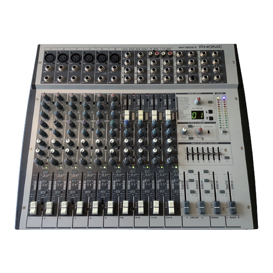
1. INTRODUCTION Congratulations on your purchase of the MM 1805(X) Mixer with built-in 255 programmed digital effects(MM only). The MM 1805(X) is 1805X built into a rugged construction, which is ideal for both touring and fixed PA installations. In order to get the best performance of the MM 1805(X), please read this owner manual carefully, and look after it. -
Page 6: Front-Panel Description
Standard connection as tip-ring-sleeve for send-return-ground. Properly utilize the outboard gears is the general practice for the working pro. Please check out Phonic lines of signal processor products; such as PCL 3200, PCL 4200 . . TRIM This rotary knob adjusts the channel signal level. Too high, the signal will distort as it overloads the channel. - Page 7 . HIGH Each input channel except 7~14 of the MM 1805(X) has a three-band swept EQ. Turn to the right to boost high frequency, adding crispness to cymbals, vocals and electronic instruments. Turn to the left to cut this frequency, reducing sibilance or hiss.
- Page 8 . AUX This rotary fader sends out the channel signal to AUX bus. The signal can be pre-fader so that the aux send will not be affected by the fader, which is suitable for foldback or monitor; it can be Post-fader, which is suitable for effects signal that fade up and fade down with the fader.
- Page 9 . GP GROUP SWITCH The input channel signal always routes to ST; press the GP switch rout the channel signal to the GP output only, Select GP1 or GP 2 by channel PAN control. Turn fully to the left, the channel signal will be routed to GP 1; turn fully to the right, the channel signal will be routed to GP 2;...
- Page 10 shaped Polar Pattern is called a cardioid microphone. The cardioid is most sensitive to the sounds which are arriving from the front, the sounds which are arriving from 90 degrees to the side is 6 Decibels less sensitive to the front .
-
Page 11: Stereo Channel 7~14
2.1.2 Stereo Channel 7~14 These 4 stereo input channels are designed for stereo line level signal, stereo source such as keyboards, drum machines, synths, hi-fi equipment or DAT players, It has the same function as mono channel except TRIM setting, 2 band EQ and balance adjustment. . - Page 12 . BALANCE The BALANCE control sets the amount of the channel signal feeding the ST mix output, allowing you to balance the source in the stereo image. When the control knob turn fully to the left or right, you send only that side of the signal to the mix.
-
Page 13: Output & Input Sockets
Outputs . MAIN OUT These sockets send line level signals (after the Main Mix, before the graphic equalizer) from the MM 1805(X) to external devices (for example: EQ or a power amplifier). . MAIN INS These sockets send line level signals (after the Main Master control) to external effects (for example: a compressor, limiter, gate, etc) and return to the MM 1805(X). - Page 14 . 2T REC The signals are sent to the tape recorder via the associate RCA socket. . EFX OUT This socket sends out the signals from mix bus. . AUX OUT This socket sends out the signals from aux bus. Inputs .
- Page 15 . AUX RTN FADER This fader controls the AUX RETURN level. . EFX RTN FADER This fader controls the EFFECT RETURN level. . AUX OUT FADER This fader controls the AUX OUT level. . EFX OUT FADER This fader controls the mix signals level to send to the built-in effect or external effect.
- Page 16 . 2T RTN /CTRL RM ON SWITCH Push down this button feeds the 2T RTN signals into control room. . MASTER Push down this button feeds the 2T RTN signal to the master output and its indicated LED lights. . PHANTOM PWR This switch turn the master phantom power on and off.
-
Page 17: Digital Effect (1805X Only)
2.1.4 Digital Effect (1805X only) The built-in 255 programmed Digital Effect is operated by the pattern selec- tion buttons. Use the rotary mode selector to select one effect out of the 255 programs. HOW TO USE THE BUILT-IN EFFECT PROCESSOR 1. -
Page 18: Graphic Equalizer
.A full 31-band EQ is recommended for that purpose, please refer PHONIC 29-band or 31- band EQ(PHONIC MQ3229/4130/4230 or MQ 3300/3600). - Page 19 right channel of the stereo mix, push down the L button, the LED on the button will light,it means you patched the Group signal to the left channel of the ST (66) outputs, push down both the L and R buttons, the LEDs on the L and R will light, it means you patched the group signals to the both sides of the ST outputs.
- Page 20 EXAMPLE 2 If only a mono PA output is required, one channel of the amplifier can be fed from the Mono Output by overplugging as shown, and the second channel of the amplifier may be used to drive foldback speaker from Aux out. EXAMPLE 3 An external mixer output plugs directly into the EQ IN, providing some signal correction if required.
-
Page 21: Back-Panel Description
2.2 Back-panel Description . DIP-SWITCH Individual Phantom Power On/Off Switch of channel 1~6. . Power Supply Input Socket Connect the power supply unit to this socket. Make sure the power supply unit is not plug into mains before connecting to the mixer. . -
Page 22: Balanced/Unbalanced System
l Set the CTRL RM Level and Headphone level to about 50%. l If you want to hear what you’re doing later, plug your headphone into the phone output socket, or hook up your control room amplifier system to the Control Room outputs. l Release the channel on button, the LED will not light. - Page 23 conductors.(known as common mode signal) Because of the real signal is carried by the 2 conductors out of phase, so it is perfectly carry to the input. At the same time, the interference occurs during transmission will be identical part (common mode), because the signal conductors are run together, there is no chance they can be different, and all the interference will be removed by the balanced input amplifier.
-
Page 24: Application
3. APPLICATION 3.1 DJ MIXING 3.2 VIDEO POST-PRODUCTION... -
Page 25: Submixing
3.3 SUBMIXING... -
Page 26: Standard Connection
3.4 STANDARD CONNECTION... -
Page 27: Appendix
4. APPENDIX DIGITAL EFFECT MODE AND PATTERN EFFECT 1: ROOM EFFECT 2: HALL... - Page 28 EFFECT 3: PLATE EFFECT 4: CHAMBER...
- Page 29 EFFECT 5: GATED REVERB EFFECT 6: REVERSE REVERB...
- Page 30 EFFECT 7: MONO DELAY EFFECT 8: OFFSET DELAY...
- Page 31 EFFECT 9: MONO TAPPED DELAY...
- Page 32 EFFECT 10: MULTI-TAP & DUAL DELAY...
- Page 33 EFFECT 11: ST CHORUS EFFECT 12: ST FLANGE...
- Page 34 EFFECT 13: CHORUS + DELAY...
- Page 35 EFFECT 14: FLANGE + REVERB...
- Page 36 EFFECT 15: CHORUS + REVERB...
- Page 37 EFFECT 16: DELAY + REVERB...
-
Page 38: Specifications
5. SPECIFICATIONS...
Need help?
Do you have a question about the MM 1805 and is the answer not in the manual?
Questions and answers