Table of Contents
Advertisement
Quick Links
OPERATION & PARTS MANUAL
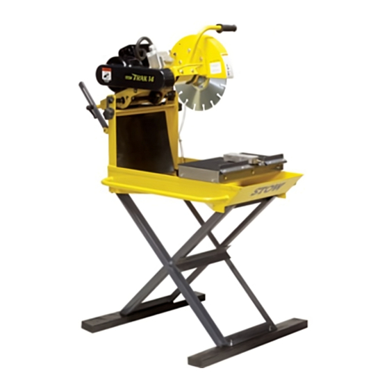
TRAK-14 SERIES
MASONRY SAWS
MS1455H (5.5 HP GASOLINE)
MS1415E (1.5 HP ELECTRIC)
MS1420E (2.0 HP ELECTRIC)
STOW CONSTRUCTION EQUIPMENT
STOW CONSTRUCTION EQUIPMENT
STOW CONSTRUCTION EQUIPMENT
STOW CONSTRUCTION EQUIPMENT
STOW CONSTRUCTION EQUIPMENT
A DIVISION OF MULTIQUIP INC.
POST OFFICE BOX 6254
CARSON, CA 90749
310-537-3700 • 888-252-STOW [888-252-7869]
FAX: 310-537-1986 • FAX: 800-556-1986
E-MAIL: stow@multiquip.com • WWW: stowmfg.com
MODEL #
SERIAL #
Revision #2 (09/07/04)
PARTS DEPARTMENT:
800-427-1244
FAX: 800-672-7877
SERVICE DEPARTMENT/TECHNICAL ASSISTANCE:
800-478-1244
FAX: 310-631-5032
P/N 25501
Advertisement
Table of Contents
Troubleshooting

Related Manuals for Stow TRAK-14 Series

Summary of Contents for Stow TRAK-14 Series
- Page 1 STOW CONSTRUCTION EQUIPMENT PARTS DEPARTMENT: A DIVISION OF MULTIQUIP INC. 800-427-1244 POST OFFICE BOX 6254 FAX: 800-672-7877 SERVICE DEPARTMENT/TECHNICAL ASSISTANCE: CARSON, CA 90749 310-537-3700 • 888-252-STOW [888-252-7869] 800-478-1244 FAX: 310-537-1986 • FAX: 800-556-1986 FAX: 310-631-5032 E-MAIL: stow@multiquip.com • WWW: stowmfg.com P/N 25501...
- Page 3 HERE'S HOW TO GET HELP PLEASE HAVE THE MODEL AND SERIAL NUMBER ON-HAND WHEN CALLING PARTS DEPARTMENT 800-427-1244 or 310-537-3700 FAX: 800-672-7877 or 310-637-3284 SERVICE DEPARTMENT 800-421-1244 FAX: 310-537-4259 TECHNICAL ASSISTANCE 800-478-1244 FAX: 310-631-5032 WARRANTY DEPARTMENT 888-661-4279, or 310-661-4279 TRAK-14 — OPERATION & PARTS MANUAL — REV. #2 (09/07/04) — PAGE 3...
-
Page 4: Table Of Contents
TRAK 14 — TABLE OF CONTENTS STOW TRAK-14 (14-Inch) HONDA GX160K1QXC9 MASONRY SAW GASOLINE ENGINE Here's How To Get Help ..........3 Air Cleaner (Cyclone) Assembly ......58-59 Table Of Contents ............. 4 Camshaft Assembly ........... 60-61 Parts Ordering Procedures ........5 Carburetor Assembly ......... -
Page 5: Here's How To Get Help
Parts Department: POST OFFICE BOX 6254 CARSON, CA 90749 Toll-free nationwide — 800-427-1244 310-537-3700 • 888-252-STOW [888-252-7869] FAX: 310-537-1986 • FAX: 800-556-1986 E-MAIL: stow@multiquip.com • WWW: stowmfg.com TRAK-14 — OPERATION & PARTS MANUAL — REV. #2 (09/07/04) — PAGE 5... -
Page 6: Safety Message Alert Symbols
This Owner's Manual has been developed to provide local regulations. complete instructions for the safe and efficient operation of the STOW TRAK-14. For engine maintenance information, please refer to the engine manufacturers Rotating Blade instructions for data relative to its safe operation. - Page 7 TRAK 14 — SAFETY MESSAGE ALERT SYMBOLS Over Speed Conditions HAZARD SYMBOLS - Gasoline Powered Models NEVER tamper with the factory settings of the Lethal Exhaust Gases engine governor or settings. Personal injury and damage to the engine or equipment can result if operating in speed ranges above Engine exhaust gases contain poisonous maximum allowable.
-
Page 8: Rules For Safe Operation
TRAK 14 — RULES FOR SAFE OPERATION CAUTION: SAFETY - GASOLINE POWERED ENGINES Failure to follow instructions in this manual may ■ NEVER touch the hot exhaust lead to serious injury or even death! This manifold, muffler or cylinder. Allow equipment is to be operated by trained and these parts to cool before servicing qualified personnel only! This equipment is... - Page 9 TRAK 14 — RULES FOR SAFE OPERATION SAFETY - ELECTRIC POWERED MODELS WARNING ■ ALWAYS connect the motor to a power source in compliance with all local electrical codes. This must be performed by a qualified electrician. ■ ALWAYS check to make sure that the ■...
- Page 10 TRAK 14 — RULES FOR SAFE OPERATION SAW TRANSPORTATION SAFETY SAW MAINTENANCE (CLEANING) ■ Use an appropriate lifting equipment to ensure the safe ■ ALWAYS clean the saw before maintenance or repair. movement of the saw. ■ DO NOT use aggressive cleaners (i.e. containing solvents). ■...
-
Page 11: Operation And Safety Decals
TRAK 14 — OPERATION AND SAFETY DECALS Machine Operation And Safety Decals The TRAK 14 SAW is equipped with a number of safety decals. These decals are provided for operator safety and maintenance information. Should any of these decals become unreadable, replacements can be obtained from your dealer. TRAK-14 —... - Page 12 TRAK 14 — SPECIFICATIONS (SAW/ENGINE) i f i o i t x " x " " 7 o i s s b l ) . g c i r r o t r e t y l l t o r b i s c i r c i r...
- Page 13 TRAK 14 — DIMENSIONS Figure 1. Dimensions c i r ) r o i l o . n i . n i . n i . 6 ( ) s r ) s r TRAK-14 — OPERATION & PARTS MANUAL — REV. #2 (09/07/04) — PAGE 13...
-
Page 14: General Information
14-inch (356 mm) Diamond Blades ™ that match the material being cut. Ask your dealer, or call STOW about your specific cutting application. PAGE 14 — TRAK-14 — OPERATION & PARTS MANUAL — REV. #2 (09/07/04) - Page 15 NOTE PAGE TRAK-14 — OPERATION & PARTS MANUAL — REV. #2 (09/07/04) — PAGE 15...
-
Page 16: Controls And Components
TRAK 14 — CONTROLS AND COMPONENTS Figure 2. Trak-14 Saw (Electric/Gasoline) PAGE 16 — TRAK-14 — OPERATION & PARTS MANUAL — REV. #2 (09/07/04) - Page 17 TRAK 14 — CONTROLS AND COMPONENTS Figure 2 shows the location of the basic controls or components 16. Carrying Handle (Tray) – Grip this handle (right-side) to for the TRAK-14 saw. Listed below is a brief explanation of each trasport the saw. control or component.
-
Page 18: Electric Motor Components
TRAK 14 — ELECTRIC MOTOR COMPONENTS Figure 3. Electric Motor Components PAGE 18 — TRAK-14 — OPERATION & PARTS MANUAL — REV. #2 (09/07/04) -
Page 19: Engine Components
TRAK 14 — ENGINE COMPONENTS Figure 4. Engine Controls and Components INITIAL SERVICING-GASOLINE ENGINE Air Cleaner – Prevents dirt and other debris from entering The engine (Figure 4) must be checked for proper lubrication and the fuel system. Remove wing-nut on top of air filter filled with fuel prior to operation. -
Page 20: Pre-Setup (Electric)
Place the conveyor cart across the water tray as shown in If using the TRAK-14 series support stand kit (P/N Figure 7. Align the wheels of the cart with the outer edge of the TRAK14SS), attach stand to the under-side of the water tray. - Page 21 Diamond Blades ™ are recommended for you saw. Ask your of-round arbor condition will cause damage to the blade STOW dealer about your specific cutting application. and the saw. 7. MAX RPM - This RPM reference is the maximum safe Saw Blade Definitions (Figure 8) operating speed for the blade selected.
- Page 22 TRAK 14 — PRE-SETUP (ELECTRIC) CAUTION CAUTION CAUTION CAUTION CAUTION Connecting the Power (Figure 10) Place the power ON/OFF switch (Figure 10) in the OFF NEVER grab or touch a live power cord position (down). (Figure 11) with wet hands , the possibility exists of electrical shock, electrocution, and even death! NEVER use a damaged or worn extension cable when...
- Page 23 TRAK 14 — PRE-SETUP (ELECTRIC) CAUTION CAUTION Dry Cutting (Electric Saws Only) CAUTION CAUTION CAUTION ALWAYS use a grounded (3-wire ) Un-plug the water pump power cord from the outlet extension cord and MAKE CERTAIN that the receptacle on the electric motor conduit box. motor is connected to a properly grounded electric circuit.
- Page 24 Loosen the 2 hex head cap screws (Figure 15) that secure the vibrations and movements of the saw. the pump mount bracket. If using the TRAK-14 series support stand kit (P/N Pull the pump handle upward to disengage the pump. TRAK14SS), attach stand to the under-side of the water tray.
- Page 25 TRAK 14 — PRE-SETUP (GASOLINE) Before Starting Read safety instructions at the beginning of manual. Clean the saw, removing dirt and dust, particularly the engine cooling air inlet, carburetor and air cleaner. Check the air filter for dirt and dust. If air filter is dirty, replace Figure 18.
-
Page 26: Operation (Electric)
TRAK 14 — OPERATION (ELECTRIC) Start-up Electric Motor WARNING CAUTION NEVER lift the blade guard while the blade is rotating. The possibility exists of severe Read and fully understand this manual before bodily harm if fingers or hands come in starting or attempting to operate the saw . - Page 27 TRAK 14 — OPERATION (ELECTRIC) Adjust the cutting depth by pulling up or down on the Cutting Head Handle (Figure 21). This saw is designed, and is best utilized as a " Chop-Saw ". Once the mounting plate release/lock lever is released, the optimum cutting action is attained by using the Raise/Lower Handle to rotate down onto the material to be cut.
- Page 28 TRAK 14 — OPERATION (GASOLINE) Start-up Gasoline Engine 1. Place the fuel valve lever (Figure 24) to the "ON" position. WARNING Read and fully understand this manual before starting or attempting to operate the saw . Before starting the saw's electric motor make sure that the Safety , General Information , Inspection and Pre-setup sections have been completed and understood.
- Page 29 TRAK 14 — OPERATION (GASOLINE) 4. Rotate the throttle lever (Figure 27) halfway between fast and slow for starting. All cutting is done at full throttle . The WARNING engine governor speed is factory set to ensure optimum ALWAYS cut with the saw at FULL THROTTLE. Attempting to blade operating speeds.
-
Page 30: Maintenance
TRAK 14 — MAINTENANCE (SAW) Gasoline Powered Saws - To adjust belt tension, loosen the Maintenance four (4) jackshaft mounting bolts and remove the belt guard. A good preventive maintenance program of regular inspection Screw the adjusting bolt back to increase the tension. Proper and care will increase life and improve the performance of the belt tension is 4-5 lbs. - Page 31 TRAK 14 — MAINTENANCE (SAW) CAUTION CAUTION CAUTION 13. Replace the spindle bearings as soon as they begin to make CAUTION CAUTION any strange noises. Worn bearings can destroy blades very When loosening the handle lock, hold onto quickly. the front of the motor/engine plate handle to prevent the plate from raising rapidly, possible 14.
- Page 32 TRAK 14 — MAINTENANCE (ENGINE) Engine Maintenance Perform engine maintenance procedures as referenced by Table 6 below: t n i ) 3 ( l i O r i A ) 1 ( g i t l l A & s t l i l o s n i r e t...
- Page 33 TRAK 14 — MAINTENANCE (ENGINE) Maintenance DANGER : Perform the engine maintenance procedures as indicated below: DO NOT use gasoline as a cleaning solvent, DAILY because that would create a risk of fire or ■ Thoroughly remove dirt and oil from the engine and control explosion.
-
Page 34: Electric Motor Wiring Diagram
TRAK 14 — WIRING DIAGRAM - ELECTRIC MOTOR Figure 34. Electric Motor Wiring Diagram PAGE 34 — TRAK-14 — OPERATION & PARTS MANUAL — REV. #2 (09/07/04) - Page 35 NOTE PAGE TRAK-14 — OPERATION & PARTS MANUAL — REV. #2 (09/07/04) — PAGE 35...
-
Page 36: Troubleshooting (Blade)
TRAK 14 — TROUBLESHOOTING - BLADE t l u r e l r o f e r r i t t a i r t f o a i r l i s a c i i r b , k c n i c c o l R "... -
Page 37: Troubleshooting (Electric Motor)
TRAK 14 — TROUBLESHOOTING - ELECTRIC MOTOR y l r e v i . d r t i w v i t c t i . y r t i w r t c a c i i t c r t c a c i e i f i... -
Page 38: Troubleshooting (Gasoline Engine)
TRAK 14 — TROUBLESHOOTING - GASOLINE ENGINE c i f t l u i t i n i r b i t i n i s o o i t i c a l o i t i l i a l i w . - Page 39 TRAK 14 — TROUBLESHOOTING - GASOLINE ENGINE n i t i t a f s i s u j e r r v e l . r e o i t u l f i r p v i t c a l o i t i l f l...
-
Page 40: Explanation Of Code In Remarks Column
TRAK 14 — EXPLANATION OF CODE IN REMARKS COLUMN How to read the marks and remarks used in this parts book. Section 1: Items Found In the “Remarks” Column Serial Numbers-Where indicated, this indicates a serial number range (inclusive) where a particular part is used. Model Number-Where indicated, this shows that the corresponding part is utilized only with this specific model number or model number variant. -
Page 41: Suggested Spare Parts
TRAK 14 — SUGGESTED SPARE PARTS TRAK-14 MASONRY SAW 1 TO 3 UNITS TRAK-14 MASONRY SAW 1 TO 3 UNITS Electric Motor Models Gasoline Engine Model Qty. Description Qty. Description 2 .... 15503 ....KNOB, COMFORT GRIP 2 .... 15503 ....KNOB, COMFORT GRIP 2 .... -
Page 42: Nameplate And Decals
TRAK 14 — NAME PLATE AND DECALS NAMEPLATE AND DECALS PAGE 42 — TRAK-14 — OPERATION & PARTS MANUAL — REV. #2 (09/07/04) - Page 43 DECAL, READ OPERATORS MANUAL 22122-001 DECAL, SERIOUS INJURY WARNING 15580 DECAL, RESPIRATORY WARNING 26180-001 DECAL, STOW TRACK-14 LOGO 25349-001 DECAL, GUARD WARNING PLATE, MODEL/SERIAL NUMBER ....1 ..CONTACT PARTS DEPT. 25215-001 DECAL, ELECTRIC CORD WARNING ....1 ..ELECTRIC MODELS ONLY...
- Page 44 TRAK 14 — TRAY ASSY. TRAY ASSY. PAGE 44 — TRAK-14 — OPERATION & PARTS MANUAL — REV. #2 (09/07/04)
- Page 45 TRAK 14 — TRAY ASSY. TRAY ASSY. PART NO. PART NAME QTY. REMARKS 29695-351 TRAY, WATER (YELLOW) 0105 SCREW. HHC 5/16 - 18 X 1-1/2 29685-001 ARM, BLADE HEIGHT ADJST. 08233-005 NUT, LOCK 5/16 - 18 GRIPCO 23853-001 SNAP HOOK, SHOWER CURTAIN 23848-001 CURTAIN, SPLASH 23858-001...
- Page 46 TRAK 14 — CART ASSY. CART ASSY. PAGE 46 — TRAK-14 — OPERATION & PARTS MANUAL — REV. #2 (09/07/04)
-
Page 47: Cart Assembly
TRAK 14 — CART ASSY. CART ASSY. PART NO. PART NAME QTY. REMARKS 23804-002 MAT, RUBBER V-RIB 11.91 X 10.10 23804-001 MAT, RUBBER V-RIB 5.79 X 10.10 24569-001 INSERT 24289-001 CART, CONVEYOR 0730 SCREW, HHC 1/4 - 20 X 1 08233-004 NUT, LOCK 1/4 - 20 GRIPCO 23793-001... - Page 48 TRAK 14 — MOTOR PLATE & SHAFT ASSY. MOTOR PLATE & SHAFT ASSY. PAGE 48 — TRAK-14 — OPERATION & PARTS MANUAL — REV. #2 (09/07/04)
- Page 49 TRAK 14 — MOTOR PLATE & SHAFT ASSY. MOTOR PLATE & SHAFT ASSY. PART NO. PART NAME QTY. REMARKS 26138-001 GRIP, HAND 29707-351 PLATE, ELECTRIC MOTOR (YELLOW) 29708-351 PLATE, GASOLINE ENGINE (YELLOW) 23846-001 SPRING, 6 X 1.5 X 1.77 WIRE 12391-004 WASHER, FLAT 1/4 AN970-4 0181 B...
- Page 50 TRAK 14 — ENGINE HONDA 5.5 H.P. ENGINE HONDA 5.5 H.P. PAGE 50 — TRAK-14 — OPERATION & PARTS MANUAL — REV. #2 (09/07/04)
-
Page 51: Engine-Honda 5.5 H
TRAK 14 — ENGINE HONDA 5.5 H.P. ENGINE HONDA 5.5 H.P. PART NO. PART NAME QTY. REMARKS 22052-404 ENGINE, HONDA 5.5 H.P. 2623 SCREW, HHC 5/16 - 18 X 1-1/4 0161 C WASHER, LOCK 5/16 0300 B WASHER, FLAT 5/16 29724-001 BRACKET, MOUNTING 27058-001... - Page 52 TRAK 14 — ELECTRIC MOTOR ELECTRIC MOTOR PAGE 52 — TRAK-14 — OPERATION & PARTS MANUAL — REV. #2 (09/07/04)
- Page 53 TRAK 14 — ELECTRIC MOTOR ELECTRIC MOTOR PART NO. PART NAME QTY. REMARKS 23871-403 ELECTRIC MOTOR, 1-1/2 HP 25140-402 ELECTRIC MOTOR, 2 HP 0627 KEY, 3/16 X 1-1/4 23863-001 PULLEY (MOTOR) 08696-006 SCREW, SHS 1/4 - 20 X 3/8 29053-501 BELT GUARD 521003 BELT - AX-34...
- Page 54 TRAK 14 — WATER PUMP ASSY. (GASOLINE ONLY) WATER PUMP ASSY. (GASOLINE ONLY) PAGE 54 — TRAK-14 — OPERATION & PARTS MANUAL — REV. #2 (09/07/04)
- Page 55 TRAK 14 — WATER PUMP ASSY. (GASOLINE ONLY) WATER PUMP ASSY. (GASOLINE ONLY) PART NO. PART NAME QTY. REMARKS 28917-001 PULLEY, WATER PUMP 3" 10138 SCREW, SHS 1/4 - 20 X 1/2 28910-001 PUMP SHAFT 25799-001 HAND GRIP 10120-010 SCREW, RHM 1/4 - 20 X 5/8 28964-001 BRACKET, PUMP MOUNT 0166 A...
- Page 56 TRAK 14 — SUPPORT STAND ASSY. SUPPORT STAND ASSY. (Option) PAGE 56 — TRAK-14 — OPERATION & PARTS MANUAL — REV. #2 (09/07/04)
- Page 57 TRAK 14 — SUPPORT STAND ASSY. SUPPORT STAND ASSY. (OPTION) PART NO. PART NAME QTY. REMARKS 23748-351 STAND ASSEMBLY OUTER 23747-351 STAND ASSEMBLY INNER 25396-001 PLATFORM STAND 2X4 TREX WOOD POLYMER 26045-001 BUSHING 07030-006 WASHER, FLAT 3/8" 06501-010 SCREW, HHCS 3/8-16 X 1-1/4 08233-006 LOCK NUT 3/8-16"...
- Page 58 HONDA GX160K1QXC9 — AIR CLEANER ASSY. AIR CLEANER (CYCLONE) ASSY. PAGE 58 — TRAK-14 — OPERATION & PARTS MANUAL — REV. #2 (09/07/04)
- Page 59 HONDA GX160K1QXC9 — AIR CLEANER ASSY. AIR CLEANER (CYCLONE) ASSY. PART NO. PART NAME QTY. REMARKS 16271ZE1000 GASKET, ELBOW 17210ZE1505 ELEMENT, AIR CLEANER (DUAL) .... 1 ..INCLUDES ITEMS W/ 17218ZE1505 FILTER, OUTER 17219733010 GASKET, AIR CLEANER COVER 17230ZE1841 COVER, AIR CLEANER (DUAL) 17232891000 GROMMET, AIR CLEANER 17238ZE7010...
- Page 60 HONDA GX160K1QXC9 — CAMSHAFT ASSY. CAMSHAFT ASSY. PAGE 60 — TRAK-14 — OPERATION & PARTS MANUAL — REV. #2 (09/07/04)
-
Page 61: Camshaft Assembly
HONDA GX160K1QXC9 — CAMSHAFT ASSY. CAMSHAFT ASSY. PART NO. PART NAME QTY. REMARKS 14100ZE1812 CAMSHAFT ASSEMBLY ....... 1 ..INCLUDES ITEMS W/ 14410ZE1010 ROD, PUSH 14431ZE1000 ARM, VALVE ROCKER 14441ZE1010 LIFTER, VALVE 14451ZE1013 PIVOT, ROCKER ARM 14568ZE1000 SPRING, WEIGHT RETURN 14711ZF1000 VALVE, INTAKE 14721ZF1000... - Page 62 HONDA GX160K1QXC9 — CARBURETOR ASSY. CARBURETOR ASSY. PAGE 62 — TRAK-14 — OPERATION & PARTS MANUAL — REV. #2 (09/07/04)
-
Page 63: Carburetor Assembly
HONDA GX160K1QXC9 — CARBURETOR ASSY. CARBURETOR ASSY. PART NO. PART NAME QTY. REMARKS 16010ZE1812 GASKET SET 16011ZE0005 VALVE SET, FLOAT 16013ZE0005 FLOAT SET 16015ZE0831 CHAMBER SET, FLOAT 16016ZH8W01 SCREW SET 16024ZE1811 SCREW SET, DRAIN ......1 ..... INCLUDES ITEMS W/ % 16028ZE0005 SCREW SET B ........ - Page 64 HONDA GX160K1QXC9 — CONTROL ASSY. CONTROL ASSY. PAGE 64 — TRAK-14 — OPERATION & PARTS MANUAL — REV. #2 (09/07/04)
-
Page 65: Control Assembly
HONDA GX160K1QXC9 — CONTROL ASSY. CONTROL ASSY. PART NO. PART NAME QTY. REMARKS 16500ZH8853 CONTROL ASSEMBLY, CYCLONE ..... 1 ..INCLUDES ITEMS W/ 16551ZE0010 ARM, GOVERNOR 16555ZE1000 ROD, GOVERNOR 16561ZE1020 SPRING, GOVERNOR 16562ZE1020 SPRING, THROTTLE RETURN 16571ZH8020 LEVER, CONTROL 16574ZE1000 SPRING, LEVER 16575ZH8000 WASHER, CONTROL LEVER... - Page 66 HONDA GX160K1QXC9 — CRANKCASE COVER ASSY. CRANKCASE COVER ASSY. PAGE 66 — TRAK-14 — OPERATION & PARTS MANUAL — REV. #2 (09/07/04)
- Page 67 HONDA GX160K1QXC9 — CRANKCASE COVER ASSY. CRANKCASE COVER ASSY. PART NO. PART NAME QTY. REMARKS 11300ZE1641 COVER ASSY., CRANKCASE U- TYPE ....1..... INCLUDES ITEMS W/ 11381ZH8801 GASKET, CASE COVER (NON-ASBESTOS) 15600ZE1003 CAP ASSEMBLY, OIL FILLER ........1..... INCLUDES ITEMS W/ # 15600ZG4003 CAP ASSEMBLY, OIL FILLER ........
- Page 68 HONDA GX160K1QXC9 — CRANKSHAFT ASSY. CRANKSHAFT ASSY. PAGE 68 — TRAK-14 — OPERATION & PARTS MANUAL — REV. #2 (09/07/04)
- Page 69 HONDA GX160K1QXC9 — CRANKSHAFT ASSY. CRANKSHAFT ASSY. PART NO. PART NAME QTY. REMARKS 13310ZE1601 CRANKSHAFT (Q- TYPE) 90745ZE1600 KEY 4.78X4.78X38 TRAK-14 — OPERATION & PARTS MANUAL — REV. #2 (09/07/04) — PAGE 69...
- Page 70 HONDA GX160K1QXC9 — CYLINDER BARREL ASSY. CYLINDER BARREL ASSY. PAGE 70 — TRAK-14 — OPERATION & PARTS MANUAL — REV. #2 (09/07/04)
- Page 71 HONDA GX160K1QXC9 — CYLINDER BARREL ASSY. CYLINDER BARREL ASSY. PART NO. PART NAME QTY. REMARKS 12000ZH8811 CYLINDER ASSEMBLY , OIL ALERT ..1 ..INCLUDES ITEMS W/ 15510ZE1033 SWITCH ASSEMBLY, OIL LEVEL 16510ZE1000 GOVERNOR ASSEMBLY ......1 ..INCLUDES ITEMS W/ # 16511ZE1000 WEIGHT, GOVERNOR 16512ZE1000...
- Page 72 HONDA GX160K1QXC9 — CYLINDER HEAD ASSY. CYLINDER HEAD ASSY. PAGE 72 — TRAK-14 — OPERATION & PARTS MANUAL — REV. #2 (09/07/04)
-
Page 73: Cylinder Head Assembly
HONDA GX160K1QXC9 — CYLINDER HEAD ASSY. CYLINDER HEAD ASSY. PART NO. PART NAME QTY. REMARKS 12210ZH8000 CYLINDER HEAD........1 ..INCLUDES ITEMS W/ 12204ZE1306 GUIDE, VALVE OS (OPTIONAL) 12205ZE1315 GUIDE, EXHAUST VALVE OS (OPT.) ..1 ..INCLUDES ITEMS W/ # 12216ZE5300 CLIP, VALVE GUIDE 12251ZF1800... - Page 74 HONDA GX160K1QXC9 — FAN COVER ASSY. FAN COVER ASSY. PAGE 74 — TRAK-14 — OPERATION & PARTS MANUAL — REV. #2 (09/07/04)
- Page 75 HONDA GX160K1QXC9 — FAN COVER ASSY. FAN COVER ASSY. PART NO. PART NAME QTY. REMARKS 19610ZE1000ZA COVER, FAN *R8* BRIGHT RED 19611ZH8810 PLATE, SIDE (OIL ALERT) 90601ZH7013 CLIP, HARNESS 19630ZH8000 SHROUD 32197ZH8003 SUB- HARNESS 36100ZE1015 SWITCH ASSEMBLY, ENGINE STOP 36100ZH7003 SWITCH ASSEMBLY, ENGINE STOP 90013883000 BOLT, FLANGE 6X12 (CT200)
- Page 76 HONDA GX160K1QXC9 — FLYWHEEL ASSY. FLYWHEEL ASSY. PAGE 76 — TRAK-14 — OPERATION & PARTS MANUAL — REV. #2 (09/07/04)
- Page 77 HONDA GX160K1QXC9 — FLYWHEEL ASSY. FLYWHEEL ASSY. PART NO. PART NAME QTY. REMARKS 13331357000 KEY, SPECIAL WOODRUFF 25X18 19511ZE1000 FAN, COOLING 28451ZH8003 PULLEY, STARTER 31100ZE1010 FLYWHEEL 31100ZE1810 FLYWHEEL, LAMP 90201878003 NUT, SPECIAL 14MM TRAK-14 — OPERATION & PARTS MANUAL — REV. #2 (09/07/04) — PAGE 77...
- Page 78 HONDA GX160K1QXC9 — FUEL TANK ASSY. FUEL TANK ASSY. PAGE 78 — TRAK-14 — OPERATION & PARTS MANUAL — REV. #2 (09/07/04)
- Page 79 HONDA GX160K1QXC9 — FUEL TANK ASSY. FUEL TANK ASSY. PART NO. PART NAME QTY. REMARKS 16854ZH8000 RUBBER, SUPPORTER 107MM 16955ZE1000 JOINT, FUEL TANK 17510ZE1020ZA TANK, FUEL *NH31* MCKINLEY WHITE 17620ZH7023 CAP, FUEL FILLER 17631ZH7003 GASKET, FUEL FILLER CAP 89218ZE1000 WRENCH, SPARK PLUG 91353671003 O-RING 13.5X1.5 (ARAI) 9405006000...
- Page 80 HONDA GX160K1QXC9 — IGNITION COIL ASSY. IGNITION COIL ASSY. PAGE 80 — TRAK-14 — OPERATION & PARTS MANUAL — REV. #2 (09/07/04)
- Page 81 HONDA GX160K1QXC9 — IGNITION COIL ASSY. IGNITION COIL ASSY. PART NO. PART NAME QTY. REMARKS 30500ZE1033 COIL ASSEMBLY, IGNITION 30700ZE1013 CAP ASSEMBLY, NOISE SUPPRESSOR 36101ZE1010 WIRE, STOP SWITCH 370MM 90121952000 BOLT, FLANGE 6X25 TRAK-14 — OPERATION & PARTS MANUAL — REV. #2 (09/07/04) — PAGE 81...
- Page 82 HONDA GX160K1QXC9 — MUFFLER ASSY. MUFFLER ASSY. PAGE 82 — TRAK-14 — OPERATION & PARTS MANUAL — REV. #2 (09/07/04)
- Page 83 HONDA GX160K1QXC9 — MUFFLER ASSY. MUFFLER ASSY. PART NO. PART NAME QTY. REMARKS 18310ZE1821 MUFFLER, SILENT 18315ZE1000 STAY, MUFFLER 18320ZF1H51 PROTECTOR, MUFFLER 18331883810 CAP, MUFFLER 18355ZE1810 ARRESTER, SPARK (SILENT) 18381ZH8800 GASKET, MUFFLER 90016ZE1000 BOLT, FLANGE 6X13 90050ZE1000 SCREW, TAPPING 5X8 90055ZE1000 SCREW, TAPPING 4X6 94001080000S...
- Page 84 HONDA GX160K1QXC9 — PISTON AND RINGS ASSY. PISTON AND RINGS ASSY. PAGE 84 — TRAK-14 — OPERATION & PARTS MANUAL — REV. #2 (09/07/04)
-
Page 85: Piston Assembly
HONDA GX160K1QXC9 — PISTON AND RINGS ASSY. PISTON AND RINGS ASSY. PART NO. PART NAME QTY. REMARKS 13010ZF1023 RING SET, PISTON (STANDARD) 13010ZH8941 RING SET, PISTON (STANDARD 13011ZF1023 RING SET, PISTON (OS 0.25) (OPTIONAL) 13011ZH8941 RING SET, PISTON (OS 0.25) (OPTIONAL) 13012ZF1023 RING SET, PISTON (OS 0.50) (OPTIONAL) 13012ZH8941... - Page 86 HONDA GX160K1QXC9 — RECOIL STARTER ASSY. RECOIL STARTER ASSY. PAGE 86 — TRAK-14 — OPERATION & PARTS MANUAL — REV. #2 (09/07/04)
- Page 87 HONDA GX160K1QXC9 — RECOIL STARTER ASSY. RECOIL STARTER ASSY. PART NO. PART NAME QTY. REMARKS 28400ZH8013ZA STARTER ASSY., RECOIL *R8*BRIGHT RED ..... 1 ..INCLUDES ITEMS W/ 28410ZH8003ZA CASE, RECOIL STARTER *R8* BRIGHT RED 28420ZH8013 REEL, RECOIL STARTER 28422ZH8013 RATCHET, STARTER 28433ZH8003 GUIDE, RATCHET 28441ZH8003...
- Page 88 HONDA GX160K1QXC9 — GASKET KIT ASSY. GASKET KIT ASSY. NO ART WORK PAGE 88 — TRAK-14 — OPERATION & PARTS MANUAL — REV. #2 (09/07/04)
- Page 89 HONDA GX160K1QXC9 — GASKET KIT ASSY. GASKET KIT ASSY. PART NO. PART NAME QTY. REMARKS 11381ZH8801 GASKET, CASE COVER (NON- ASBESTOS 12251ZF1800 GASKET, CYLINDER HEAD 12391ZE1000 GASKET, CYLINDER HEAD COVER 16212ZH8800 GASKET, INSULATOR 16221ZH8801 GASKET, CARBURETOR 18381ZH8800 GASKET, MUFFLER 06111ZH8405 GASKET KIT ............
- Page 90 HONDA GX160K1QXC9 — LABELS ASSY. LABELS ASSY. PAGE 90 — TRAK-14 — OPERATION & PARTS MANUAL — REV. #2 (09/07/04)
- Page 91 HONDA GX160K1QXC9 — LABELS ASSY. LABELS ASSY. PART NO. PART NAME QTY. REMARKS 87521ZH8020 EMBLEM, 5.5 87522ZH9000 LABEL, CAUTION 87528ZE1810 MARK, CHOKE 87532ZH8810 MARK, OIL ALERT (E) 87534ZE1841 LABEL, AIR CLEANER CAUTION 87535ZE1840 MARK, AIR CLEANER SALES POINT TRAK-14 — OPERATION & PARTS MANUAL — REV. #2 (09/07/04) — PAGE 91...
-
Page 92: Terms And Conditions Of Sale - Parts
STOW be liable for loss of profit will be absorbed by STOW on any subsequent clearly marked. or good will or for any other special, consequential shipment applying to that order. - Page 93 NOTE PAGE TRAK-14 — OPERATION & PARTS MANUAL — REV. #2 (09/07/04) — PAGE 93...
- Page 94 STOW CONSTRUCTION EQUIPMENT PARTS DEPARTMENT: A DIVISION OF MULTIQUIP INC. 800-427-1244 POST OFFICE BOX 6254 FAX: 800-672-7877 CARSON, CA 90749 SERVICE DEPARTMENT/TECHNICAL ASSISTANCE: 310-537-3700 • 888-252-STOW [888-252-7869] 800-478-1244 FAX: 310-537-1986 • FAX: 800-556-1986 FAX: 310-631-5032 E-MAIL: stow@multiquip.com • WWW: stowmfg.com...
Need help?
Do you have a question about the TRAK-14 Series and is the answer not in the manual?
Questions and answers