
Related Manuals for Elkron MEDEA


Summary of Contents for Elkron MEDEA
- Page 1 INSTALLATION MANUAL MULTI-FUNCTION INTRUSION SYSTEM On the website www.elkron.com, you may find updated information relating to the documentation provided with the product...
- Page 2 These references and information do not imply that the manufacturer will market such products or services in the future. Elkron is a trademark of URMET S.p.A. All trademarks mentioned in this document are the property of their respective owners.
-
Page 3: Table Of Contents
Introduction ....................................7 How the manual is organised Conventions used Glossary Standards and certifications EN 50131-1 IMQ mark 11 MEDEA certifications 1 - The MEDEA system ................................12 1.1 System Architecture 1.2 Main characteristics 1.2.1 Control units 1.2.2 Interfaces (optional modules) 1.2.3 Expansion modules 1.2.4... - Page 4 Opening the lid 3.3.2 Openings for routing cables 3.3.3 Fixing to the wall 3.3.4 Fixing the battery 3.4 Wall mounting the MEDEA control unit (metal box) 3.4.1 Opening the lid 3.4.2 Openings for routing cables 3.4.3 Fixing to the wall 3.5 Expansion board assembly in the control unit...
- Page 5 6.4.2 Total reset from keypad and configurator 6.4.3 Reset Master, Technician, Technician Manager and User codes from keypad 6.4.4 Reset user codes from configurator (MEDEA CONTROL) 6.4.5 Reset of all codes (hardware from control unit) 6.4.6 Total reset (hardware) 6.4.7 Deleting wireless devices from an individual ER700-RF receiver 6.4.8...
- Page 6 Figure 51 - MEDEA PE connection in metal box .......................... 58 Figure 52 - MEDEA backup battery connection 7.2 Ah for MEDEA /32 or 9 Ah for MEDEA /64 and MEDEA /160 ...... 59 Figure 53 - MEDEA backup battery connection 18 Ah ........................59 Figure 54 - MEDEA battery fixing in ABS box ..........................
- Page 7 Figure 65 - ER700-RF tamper connection ............................ 64 Figure 66 - KP710 tamper................................64 Figure 67 - DK700 tamper connection ............................65 Figure 68 - MEDEA/32 input position ............................66 Figure 69 - MEDEA/64/160 input position ............................. 67 Figure 70 - MEDEA/64/160 PrIO position ............................. 67 Figure 71 - EP708 PrIO position ..............................
- Page 8 Table 6 - Devices that can be managed by the CPU ........................15 Table 7 - Maximum number of wired and wireless I/O expansion modules .................. 15 Table 8 - MEDEA system functions .............................. 17 Table 9 - Events generated by mains voltage ..........................20 Table 10 - Checking and charging the battery ..........................
-
Page 9: Introduction
Technical specifications of the control panel and the various devices. Two complementary documents can be downloaded from the Elkron website to help you with your design: • The parts of an intrusion alarm system provides basic knowledge about alarm systems: how they are made, what they can do, how they work and what devices form them. -
Page 10: Glossary
Combine the "First entry" and "Last exit" behaviours to enable the use of the same Last exit access door for both exit and entry. Protocol Set of rules that govern the exchange or the transmission of data among devices. PSTN Public Switched Telephone Network indicates the telephone land line. MEDEA Installation Manual... -
Page 11: Standards And Certifications
Grade 3 It is indicated for commercial and industrial premises, as well as for residential Average-high risk premises with a high value. The system is usually connected with a Security Service. MEDEA Installation Manual... - Page 12 EN 50131-1 establishes four levels of user access that define the ability of users to access system components and controls: Level 1 Access by anyone. Level 2 Access by the user (e.g. an operator). Level 3 Access by the maintainer. Level 4 Access by the manufacturer. Table 3 - EN50313-1 access level MEDEA Installation Manual...
-
Page 13: Imq Mark
MEDEA certifications The MEDEA intrusion alarm system was certified at IMQ - SECURITY SYSTEMS laboratories in conformity with European standards EN 50131-1, EN 50131-3 and EN 50131-6:2017 - Grade 2 or 3 - Environmental class II - general indoors. -
Page 14: The Medea System
Figure 1 - System architecture Main characteristics The MEDEA intrusion alarm systems are modular, suitable for small - mid-sized systems in residential, industrial, and service settings. According to the final configuration, the systems are certified in Grade 2 or 3 according to EN 50131. -
Page 15: Control Units
Control units 1.2.1 The control units consist of the combination of a motherboard (CPU), available in the MEDEA/32, MEDEA/64 and MEDEA/160 versions, with a box, available in ABS and metal versions. MEDEA/32 MEDEA/64 MEDEA/160 ■ ■ ■ ABS (power supply 1.5 A, battery 7 Ah) ■... -
Page 16: Expansion Modules
DK700M-P/B: same features as DK700M-P but with white front panel. UC700-IT control unit for ZigBee and WiFi modules 1.2.6 These can be used to install a ZigBee and WiFi module if the MEDEA board is placed in a metal box. CP/EXP wall-mounted box for expansion modules 1.2.7 The ABS wall-mounted box can contain an EP708 or ER700-RF expansion module. -
Page 17: Maximum System Size
Maximum system size The choice of CPU determines the maximum number of devices that can be managed with maximum MEDEA system expansion. MEDEA/32 MEDEA/64 MEDEA/160 Inputs + outputs (in any combination) Wireless inputs Keypads on bus Activators on bus 868 MHz RF keypads... -
Page 18: Functions
■ Home automation/management/control device management ▲ ▲ ▲ Intrusion/manipulation/malfunction alarm signalling in speech ▲ ▲ SMS alarm/alarm/malfunction notification ▲ Signalling and/or interaction via Elkron Cloud ▲ Signalling or interaction via numerical message ▲ System arming/disarming command ▲ Sector arming/disarming command ▲... - Page 19 Functions ▲ Read event log command ▲ System status request Remote configuration (via PC, tablet, smartphone and Elkron ▲ Cloud) ▲ CPU firmware upgrade ▲ ■ Sensor arming command with camera ▲ ■ Interaction with home automation devices Table 8 - MEDEA system functions ▲...
-
Page 20: System Connectivity
Figure 2 - Connection to local PC Connection to security service with numeric protocol 1.5.2 Cellular telephone network traditional telephone network Figure 3 - Connection to security service (numeric protocol) Internet connection 1.5.3 WiFi Cellular telephone network Figure 4 - Internet connection MEDEA Installation Manual... -
Page 21: Self-Diagnostic Functions
Remote configuration Figure 5 - Interaction via the Internet Self-diagnostic functions The MEDEA system continuously carries out operational and efficiency checks. These are: • Power supply checks (mains voltage and battery status). • System supply voltage check. •... -
Page 22: Power Controls
Mains voltage 1.7.1 The MEDEA control unit constantly monitors the presence of 230 V~ mains voltage, which is detected through the presence of voltage from the power supply unit. The "No Power" event triggers a timer that delays the alert. The delay prevents alarms from being sent in case of short power supply interruptions or resumptions. -
Page 23: Battery Management
The "Low Battery" status persists until the first successful "Battery Test" is completed. Checking and charging the battery The MEDEA system constantly monitors the state of the battery and the charging circuit keeps it charged with a limited maximum current. The following behaviour occurs according to the presence or absence of... -
Page 24: Medea Cpu
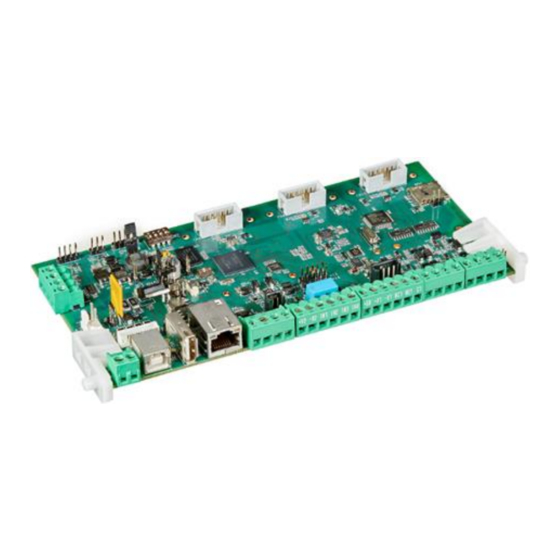
MEDEA CPU Main elements 1.8.1 IMPORTANT For a description of the terminals, see the chapter 4 - Connections. MEDEA /32 CPU CPU MEDEA /64 and MEDEA /160 CPU Figure 6 - MEDEA CPU elements MEDEA Installation Manual... - Page 25 RED LED Flashing = Bus communication PrIO 7 - programmable input/output Clock-calendar back-up battery BATT Table 11 - MEDEA CPU elements * CPU MEDEA /64 and MEDEA /160 CPU only *For connection of the ER700-RF wireless expansion interface MEDEA Installation Manual...
-
Page 26: Ep708 Expansion Module
Alarm LED (follows buzzer sound) BUS interface LEDs Flashing = Communication in progress … LED LP1 (PrIO ) … PrIO power positive (13 V⎓) PrIO power negative (Gnd) PrIO programmable input/output x (x = 1...8) Table 12 - EP708 expansion modules MEDEA Installation Manual... -
Page 27: Prio Leds
Input to earth 1 flash Balanced input Tandem input 2 flashes Alarm 1 3 flashes Alarm 2 4 flashes Alarm 1 + Alarm 2 Output on Output Output not active Table 13 - EP708 expansion module LEDs MEDEA Installation Manual... -
Page 28: Er700-Rf Expansion Module
Logic LED power (+3.3 V⎓) +3V3 ON = Power present Wireless device LED Slow flashing = No device acquired Normal flashing = At least one device acquired Fast flashing = General fault Table 14 - ER700-RF expansion modules MEDEA Installation Manual... -
Page 29: Sa700 Supplementary Power Unit
18 Ah battery) TAMPER Tamper connector Power unit tamper bypass (jumper inserted = tamper bypassed) RX2,3 Bus out 1 and 2 reception LED Board power supply present (14.4m V⎓) Board power positive (14.4 V⎓) Board power negative (Gnd) MEDEA Installation Manual... -
Page 30: Srpt700 Bus Splitter
Power positive (13.8 V⎓) output bus 1, 2 and 3 Data transmission/reception BUS A output bus 1, 2 and 3 Data transmission/reception BUS B output bus 1, 2 and 3 Output bus 1, 2 and 3 power negative (Gnd) Table 16 - SRPT700 BUS distributor elements MEDEA Installation Manual... -
Page 31: Ilt700 Interface
Yellow RING signal LED ON = RING signal detected Red LED outgoing DTMF tone generation ON = Outgoing DTMF tone generated Green LED recognition of incoming DTMF tone ON = Incoming DTMF tone recognised Table 17 - ILT700 interface elements MEDEA Installation Manual... -
Page 32: It700-Gsm Interface
LED mobile phone network connection status Fast flashing (1 flash per second) = Interface not registered Slow blinking (1 blink every 4 seconds) = Interface registered to the network SIM card slot (nano SIM size) Table 18 - IT700-GSM interface elements MEDEA Installation Manual... -
Page 33: It700-4G Interface Main Elements
Figure 13 - IT700-GSM interface elements SMA antenna connector LED mobile phone network connection status Network search, call connected Blinking Registered network interface, data connection SIM card slot (nano SIM size) Table 19 - IT700-4G interface elements MEDEA Installation Manual... -
Page 34: It700-Wifi Interface Main Elements
Connector for optional interface OPT2 Connector for optional interface TAMPER Tamper connector Tamper bypass (jumper inserted = tamper bypassed) USB type C connector +3V3 LED 3.3V⎓ power supply present LED power supply +5V⎓ present Table 21 - IT700-WiFi interface elements MEDEA Installation Manual... -
Page 35: Kp710D Keypad
PrIO power positive (13 V⎓) PrIO programmable input/output 1 PrIO programmable input/output 2 Level indicator BUS LED Keypad tamper bypass (jumper inserted = tamper bypassed) Keypad tamper Buzzer for acoustic indications Table 22 - KP710D keypad internal elements MEDEA Installation Manual... -
Page 36: Front Controls And Icons
Menu access button Button for going back to the upper menu level To confirm the access code and other entered data To confirm the chosen menu and go to the submenu. Table 23 - KP710D keypad front elements MEDEA Installation Manual... - Page 37 OFF = All sectors associated to the keypad are disarmed ON = All sectors associated to the keypad are armed Green system status LED Flashing = Some sectors associated to the keypad are armed Table 24 - KP710D keypad LED signals MEDEA Installation Manual...
-
Page 38: Dk700M-P Proximity Reader
Proximity sensor position PrIO 1 (yellow wire) PrIO 2 (green wire) Power positive (13.8 V⎓) Data transmission/reception BUS A Data transmission/reception BUS B Power negative (Gnd) Buzzer for acoustic indications Table 25 - DK700 proximity reader elements MEDEA Installation Manual... -
Page 39: Design
Calculating the total system consumption as shown in the following table. Max. allowed consumption Safety Minimum autonomy to be grade guaranteed MEDEA /32 MEDEA /64 MEDEA /160 EN 50131 with no mains power 7.2 Ah battery 9 Ah battery 18 Ah battery 60 hours... -
Page 40: Choosing The Cables
The most critical power supply situation for the system must be used to calculate the conductor cross- section area, i.e. no mains power supply and back-up battery at minimum charge (11.5 V⎓). Under these conditions, at full load, a voltage of at least 10.5 V⎓ is present at the ends of all MEDEA system components. - Page 41 29 m 43 m 2.000 A 11 m 16 m 21 m 32 m 2.500 A 13 m 17 m 26 m 3.000 A 11 m 14 m 21 m Table 28 - Maximum power cable length MEDEA Installation Manual...
-
Page 42: Rs485 Bus
As the RS485 BUS is pre-polarised, no termination of lines using resistors is normally required. Only in , yp y b w Ω Ω, special cases is it advisable to prevent abnormal operation. The BUS cable sizing is only calculated to determine the cross-section area of the "+" and "-" power cables. MEDEA Installation Manual... -
Page 43: Supplementary Power Supply Unit
It can be purchased separately to increase the availability of current and the number of devices connected to the MEDEA control unit. The board has 2 output buses and an additional power output, which can be galvanically separated from the control unit power supply by means of the jumper. -
Page 44: Installation Procedure
Installation Installation procedure The recommended sequence of operations to install an intrusion alarm system with MEDEA control panels in the shortest possible time, while guaranteeing the best result, is: Lay the cables. Open the pre-cut holes in the plastic or metal box required for cable routing, connection of cable ducts and installation of external and internal antennas. -
Page 45: Wall-Mounting The Medea Control Unit (Abs Box)
Wall-mounting the MEDEA control unit (ABS box) Opening the lid 3.3.1 Figure 21 - ABS box opening Openings for routing cables 3.3.2 The base of the control unit is equipped with pre-cut holes for routing the necessary cables (power supply, bus, detectors, etc.). -
Page 46: Fixing To The Wall
Figure 23 - Fixing holes in ABS box Fixing the battery 3.3.4 To ensure compliance with EN 50131-3, the battery must be secured using the cable tie provided. Wall mounting the MEDEA control unit (metal box) Opening the lid 3.4.1 Front removal Flap opening Rotate the front panel by 180 degrees. -
Page 47: Openings For Routing Cables
Removal protection is compulsory to guarantee EN 50131 Grade 3 certification. The tamper function can also be installed to provide anti-opening protection only. In this case, the system does not comply with EN 50131 Grade 3 certification. MEDEA Installation Manual... -
Page 48: Expansion Board Assembly In The Control Unit
Figure 28. The expected positions are shown in the figure. These positions are accessible after lifting the CPU. Fixing screw holes ER700-RF Fixing screw holes Figure 28 - Expansion board assembly in ABS box MEDEA Installation Manual... -
Page 49: Expansion Board Assembly In Metal Box
Figure 29 - Expansion board assembly in metal box MEDEA CPU assembly MEDEA CPUs are supplied separately from the ABS or metal boxes that contain them. The three CPU models (MEDEA/32, MEDEA/64 4 MEDEA/160) are mechanically identical. The CPU hinges must be inserted into the appropriate holders of the respective boxes, the CPU is then secured with fasteners (ABS box) or a screw (metal box). -
Page 50: Medea Cpu Assembly In Metal Box
MEDEA CPU assembly in metal box 3.6.2 Figure 31 - MEDEA CPU assembly in a metal box Interface assembly on the CPU board Assemble the required interface boards on the motherboard (CPU). Up to 3 interfaces can be installed, chosen from ILT700 (max. 1, preferably on OPT1), IT700-GSM or IT700-4G (max. 1, preferably on OPT2), WiFi (max. -
Page 51: Accessories For Mobile Phone Interfaces Sim Card
GSM/4G antenna assembly in plastic box 3.8.2 Figure 33 - GSM antenna assembly and connection in ABS box IMPORTANT It is recommended to tighten the SMA antenna connector on the interface firmly, but without damaging it (tightening torque 0.9 Nm). MEDEA Installation Manual... -
Page 52: Gsm/4G Antenna Assembly In Metal Box
We recommend the use of the high-gain ANT2/4G-HG antenna if the planned antenna installed does not guarantee an adequate signal level due to the position of the MEDEA control unit. The ANT2/4G BM stylus antenna can be used as an alternative to the PCB antenna supplied with the 2G/4G modules for the ABS box. -
Page 53: Installing The Kp710D Keypad
160 cm from the floor for normal installations or 120 cm for installations suitable for disabled users. Fixing hole for removal protection. Compulsory use for certification EN 50131 Grade 3. Use Ø 5 mm wall plug. Figure 38 - KP710D keypad fixing holes MEDEA Installation Manual... -
Page 54: Closing The Keypad
Figure 39 - DK700M-P / DK700M-P/B reader positioning in boxes IMPORTANT If two proximity readers are installed in the same box, leave at least the space of one module between them (the space left free can still be occupied by another device). MEDEA Installation Manual... -
Page 55: Installation Of Expansion Boxes
CP/EXP box 3.11.2 Figure 40 - CP/EXP box - opening Figure 41 - CP/EXP box - pre-cut holes for cable routing MEDEA Installation Manual... - Page 56 This requirement is not compulsory for Grade 2 or lower installations. EP708 expansion module EP708 expansion module ER700-RF expansion module Figure 43 - CP/EXP box - expansion module positions IMPORTANT Always connect and disconnect the expansion boards with the control panel not powered (mains and battery disconnect). MEDEA Installation Manual...
-
Page 57: Cp/Ep500 Box
Figure 46 - CP/EP500 housing - fixing on 3-module flush-mounted box Figure 47 - CP/EP500 box - expansion module position IMPORTANT Always connect and disconnect the expansion boards with the control panel not powered (mains and battery disconnected). MEDEA Installation Manual... -
Page 58: Connections
3 mm. It is advisable to place the isolating device upstream of the residual current circuit breaker to be able to disconnect the other sections of the electrical system while maintaining MEDEA system operation. MAINS... -
Page 59: Power Connection In Abs Box
14.4 V⎓ 230 V~ Figure 49 - MEDEA power supply connection in ABS box NOTE: Power supply in CAT II 2500 V. Once installed, the power supply is subject to transient voltages higher than those of the overvoltage category for which it was designed. For this reason, an additional transient voltage protection is required outside the device. -
Page 60: Power Connection In Metal Box
Cables Faston supplied included Figure 50 - MEDEA power supply connection in metal box IMPORTANT Fasten the mains power cables to the cable tie holders with the cable ties provided. Figure 51 - MEDEA PE connection in metal box Connect the earth conductor (yellow-green) with one end without Faston, supplied, to the terminal block of the box. -
Page 61: Backup Battery Connection
Insert the backup battery into the control unit and any additional power supplies. Figure 52 - MEDEA backup battery connection 7.2 Ah for MEDEA /32 or 9 Ah for MEDEA /64 and MEDEA /160 For connection of the 18 Ah battery of the control unit in the metal box, two Faston-connector screw adapters are supplied. -
Page 62: Rs485 Bus Connection
Central BUS connection 4.4.1 MEDEA/32 control units have only one BUS connection. The MEDEA/64 and MEDEA/160 control units have two BUS connections that are logically the same but electrically separate. Either connections can be used. In all control panels there is an additional polarised BUS connector for the alternative connection of the ER700-RF interface via a special cable. -
Page 63: Bus Expansion Module Connection
BUS expansion module connection 4.4.2 Alternative BUS connection, with special cable, to MEDEA control unit Figure 57 - ER700-RF BUS connection Figure 56 - EP708 BUS connection BUS keypad connection 4.4.3 Figure 58 - KP710 D BUS connection BUS proximity reader connection 4.4.4... -
Page 64: Bus Connection Using Bus Splitter
BUS connection using bus splitter 4.4.5 Figure 60- SRPT700 bus connection BUS connection using additional power supply unit 4.4.6 Powered by SA700 Powered by MEDEA Figure 61– SA700 connection MEDEA Installation Manual... -
Page 65: Tamper And Sabotage Input (Sab) Connection
Sabotage input (SAB) for additional tamper switches Tamper enabled Tamper disabled Central unit tamper switch Figure 63 - MEDEA tamper and SAB connection The control unit tamper switch can be disabled either via hardware (EXC jumper) or software (configurator). MEDEA Installation Manual... -
Page 66: Expansion Module Tamper Connection
If a microswitch is not connected, close the TAMPER input of the EP708 expansion module with a jumper. If a microswitch is not connected, close the TAMPER input of the ER700-RF expansion module with the EXC jumper. Keypad tamper 4.5.3 Tamper protection Tamper enabled Tamper disabled Figure 66 - KP710 tamper MEDEA Installation Manual... -
Page 67: Dk700 Tamper Connection
Tamper signal (wire short ■ ■ ■ ■ circuit) ■ ■ ■ Tamper warning (wire cut) ■ Fault/masking ■ Alarm 1 / Alarm 2 Stand-by voltage * 13.8 V Voltage with input alarm * 13.8 V 5.6 V MEDEA Installation Manual... -
Page 68: Medea Position Inputs And Prio
There is also the inertial/shutter input type used to connect detectors that generate fast signals (inertial, shutter, seismic, etc.). The connection mode is fixed (NC). This does not comply with EN 50131 because it is not protected against short circuits. MEDEA position inputs and PrIO 4.7.2 Figure 68 - MEDEA/32 input position MEDEA Installation Manual... - Page 69 Figure 69 - MEDEA/64/160 input position Figur e 70 - MEDEA/64/160 PrIO position MEDEA Installation Manual...
-
Page 70: Ep708 Prio Position
(PrIO1) and connect the external detector the external detector or button or button Figure 73 - DK700 PrIO position IMPORTANT A PrIO must be used to connect the tamper protection to comply with EN 50131 Grade 3. MEDEA Installation Manual... -
Page 71: Input Wiring Diagram
IMPORTANT The inputs must not be programmed as NORMALLY OPEN to comply with EN 50131 standards because in this case they would not be protected against short-circuiting and wire cutting. IMPORTANT Unused inputs do not need to be closed because they can be disabled by programming. MEDEA Installation Manual... -
Page 72: Output Connection
Normally energised programmed relay Normally de-energised programmed relay (positive safety) Stand-by Active Stand-by Active Table 32 - Relay output stand-by states Advice: To reduce current consumption, it is advisable to program all unused relay outputs as normally de-energised. MEDEA Installation Manual... -
Page 73: Output Position On Medea
2 (electrical) Figure 74 - MEDEA output position PrIO configured as output 4.8.3 NOTE: For the location of the PrIOs in the various devices see 4.7.2 MEDEA position inputs and following. The electrical outputs can be individually configured as: • “... -
Page 74: Siren Connection
IMPORTANT Max. withdrawable current from +V 500 mA for EP708 installed inside the control unit box or at close distance. In the case of remote connection, size the cables appropriately to minimise voltage drop. MEDEA Installation Manual... -
Page 75: Hpa800 And Internal Siren Connection Diagrams
Siren in default configuration (unbalanced inputs, positive reference). Relay 1 of the MEDEA control unit must be programmed (intrusion or intrusion/tamper, normally energised). The value of the balancing resistors required for the SAB input of the MEDEA control unit is 15 kΩ MEDEA Installation Manual... - Page 76 UNIT Siren in default configuration (unbalanced inputs, positive reference). Relay 1 of the MEDEA control unit must be programmed (intrusion or intrusion/tamper, normally energised). Output U2 must be associated with an armed sector (OR TC or AND TC), with positive present kΩ...
- Page 77 UNIT Siren with balanced inputs (B4 OFF), positive reference. Relay 1 of the MEDEA control unit must be programmed (intrusion or intrusion/tamper, normally energised). Output U2 must be associated with an armed sector (OR TC or AND TC), with positive present kΩ...
-
Page 78: Connection Of Ilt700 Telephone Interface
ADDITIONAL LINE TELEPHONE PROTECTION Figure 78 - ILT700 connections MEDEA Installation Manual... -
Page 79: Connection Types With Traditional Line (Pstn)
Connection to PSTN simple telephone line ADDITIONAL LINE PROTECTION Figure 79 - PSTN line connection diagram Connection to PSTN telephone line with ADSL ADSL ADDITIONAL LINE FILTER PROTECTION ADSL MODEM Figure 80 - PSTN connection diagram with ADSL MEDEA Installation Manual... -
Page 80: Commissioning
5. The PWR and +3V3 LEDs light up on the expansion modules when they are powered. When the CPU is working, the BUS LED flashes. 6. Check that the voltages present on the devices comply with the requirements described in section 3.2.3 in the various points in the system. Power conductor size. MEDEA Installation Manual... -
Page 81: Maintenance
2. Enable the Technician code with Master code (default 111111). Then exit the Master menu. 3. Using MEDEA control unit, enter the technical code (default 000000) and access the control unit 4. Using the keypad, enter the Installer code (default: 000000) and press the MENU button. The operating menu is accessed and the system automatically switches to maintenance mode. - Page 82 ■ = Return to default configuration □ = Device remains but is reset to default configuration = Device remains acquired but reset to default configuration ◊ = Device is cleared and reset to factory configuration ● = Deleted MEDEA Installation Manual...
-
Page 83: Partial Reset From Keypad And Configurator
Press the OK button and then the OK button again to confirm the operation. The code is reset to default settings. The operation must be carried out for each individual code to be set to DEFAULT. Reset user codes from configurator (MEDEA CONTROL) 6.4.4 Proceed as follows to reset a single user code. -
Page 84: Reset Of All Codes (Hardware From Control Unit)
In this case, the app cannot be used but updates are possible. The operation described restores the board to default settings and the control unit LAN port address to DHCP. IMPORTANT The following will be cleared: LOG, KEYS and CODES MEDEA Installation Manual... -
Page 85: Deleting Wireless Devices From An Individual Er700-Rf Receiver
Table 36 - SW2 DIP switch functions * if set to ON before POWER ON or reset. To carry out code reset and total reset operations, follow the instructions given in the sections on system maintenance and system RESET. MEDEA Installation Manual... -
Page 86: Replacing The Battery
Disconnect any self-powered sirens and disconnect their batteries because they will sound for the set time if the power is removed (if provided with this function). Disconnect the mains voltage. Disconnect the battery. If additional power supply units are present, disconnect them in the same sequence (points 2 and 3). MEDEA Installation Manual... -
Page 87: Technical Specifications
100 mA Sabotage input (24h) Relay: 1 Relay: 1 Relay: 1 Outputs O.C. : 1 O.C. : 1 O.C.: 1 SR output (for self-powered devices, e.g. siren) PrIO RS485 BUS connections Ethernet port (LAN) USB port type A MEDEA Installation Manual... - Page 88 Max. number of technicians (Installer) Max. number of Technical Managers Max. number of users Maximum number of possible code combinations from 10,000 to 1,000,000 EXPANDABILITY EP708 (I/O wired expansion modules) ER700-RF (wireless expansion modules) ER700-ZB (ZigBee expansion module) MEDEA Installation Manual...
- Page 89 4. A line fault must be recognised within 20 seconds (SP6) to ensure compliance with EN50136-2 in the configuration of the LAN. DP1 guaranteed with: Primary LAN and alternate ILT700 interface. DP2 guaranteed with: Primary LAN and alternative IT700-GSM interface, with periodic test not exceeding 30 min. enabled. MEDEA Installation Manual...
-
Page 90: Abs Box
50 mA Max. current deliverable from all terminals 750 mA Dimensions (L x H) 89 x 75 mm Maximum bus length 500 metres (cable cross-section 2x0.75 mm power supply + 2x0.22 data) EN50131 certification Grade 3 Class II MEDEA Installation Manual... -
Page 91: Er700-Rf Expansion Module
The line control must be enabled with a time not exceeding 25h to ensure compliance with EN50136-2 in the configuration of the interface. (SP2) or 3 min. (SP4). DP1 guaranteed with: IT700-GSM primary interface and ILT700 alternate interface. DP2 guaranteed with: IT700-GSM primary interface and alternative LAN connection with 30 min periodic test. MEDEA Installation Manual... -
Page 92: It700-4G Interface
Working voltage 10 - 14.5 V⎓ Nominal stand-by current < 45.0 mA ZigBee profile Home Automation 1.2 Radio-frequency 2.4 GHz Output power 17 dBm Reception sensitivity -101 dBm Transmission speed 250 kbit/s Range (free field) 200 m MEDEA Installation Manual... -
Page 93: Kp710D Keypad
500 metres power supply + 2 x 0.22 mm data) EN50131 certification Grade 3 Class II This installation manual refers to version SW 1.5_100 of MEDEA control units and version FW 1.1_25 of BUS line peripheral devices MEDEA Installation Manual... - Page 94 For more information about where you can drop off your waste equipment for recycling, please contact your local city office, your household waste disposal service or the shop where you purchased the product. MEDEA Installation Manual...
- Page 96 Tel. +39 011.3986711 - Fax +39 011.3986703 www.elkron.com info@elkron.it Elkron is è trademark of URMET S.p.A. Via Bologna, 188/C - 10154 Torino (TO) – Italy www.urmet.com MEDEA Installation Manual MADE IN ITALY...
Need help?
Do you have a question about the MEDEA and is the answer not in the manual?
Questions and answers