
Related Manuals for Elkron EL50RT 2PH


Summary of Contents for Elkron EL50RT 2PH
- Page 1 EL50RT 2PH 150m Barriere ad infrarossi da esterno Infrared Outdoor barriers Barrières extérieures à infrarouge DS80EL15-001 LBT80363 IS1212-AA 1/28 EL50RT 2PH 150m...
-
Page 2: Table Of Contents
2.0 AVERTISSEMENTS POUR L'INSTALLATION.................19 3.0 CONNEXIONS ..........................20 4.0 INSTALLATION.........................21 5.0 REGLAGE DU TEMPS D'INTERVENTION ................21 6.0 CONFIGURATION DES FREQUENCES DE TRAVAIL............23 7.0 ALIGNMENT OPTIQUE ET PROGRAMMATION ..............23 8.0 GUIDE DE DEPANNAGE ......................25 9.0 CARACTERISTIQUES TECHNIQUES ..................26 10.0 DIMENSIONS .........................26 2/28 EL50RT 2PH 150m... -
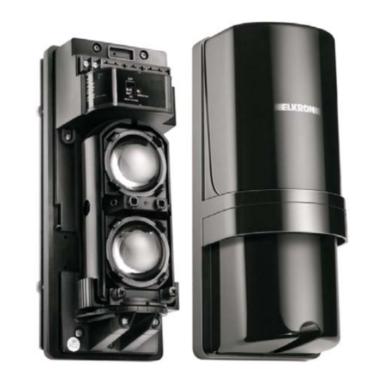
Page 3: Descrizione Componenti
Una forte illuminazione sporca o da spruzzi di acqua ed il ricevitore diretta per lungo tempo può di mare. influire sulla vita del prodotto. 3/28 EL50RT 2PH 150m... -
Page 4: Connessioni
3.0 CONNESSIONI - TRASMETTITORE - RICEVITORE Alimentazione Alimentazione Uscita Tamper 10,5Vdc – 30 Vdc 10,5Vdc – 30 Vdc Uscita Allarme Contatto pulito non polarizzato non polarizzato Relè contatto pulito Uscita NC Uscita NC/NA 28Vdc/0,2A 28Vdc/0,2A 4/28 EL50RT 2PH 150m... -
Page 5: Installazione
- Far passare il cavo di collegamento nel foro della piastra di fissaggio e fissare la piastra al muro con le viti (1/6 – x3/4-). - Effettuare i collegamenti in morsettiera. - Dopo la verifica dell’allineamento e del corretto funzionamento, riposizionare il coperchio e fissare saldamente la vite di chiusura. 5/28 EL50RT 2PH 150m... -
Page 6: Regolazione Tempo Di Intervento
Corsa veloce Passo normale Movimento lento Nota: al termine dell'installazione è necessario effettuare un test del tempo di intervento che è stato impostato. Questa funzione permette di adattare la sensibilità della barriera all'ambiente che la circonda. 6/28 EL50RT 2PH 150m... -
Page 7: Impostazione Frequenze Di Lavoro
Senso antiorario: verso il basso Regolazione Orizzontale - Collegare un voltmetro (DC10V) ai morsetti Monitor + e Monitor – sul ricevitore. - Effettuare la regolazione fine dell'allineamento ottico del trasmettitore per ottenere il massimo valore di tensione sul voltmetro. 7/28 EL50RT 2PH 150m... -
Page 8: Allineamento Ottico E Programmazione Funzionamento
(2) Rimuovere con attenzione il filtro di attenuazione e ricontrollare la tensione ai morsetti Monitor. LED allarme LED attenuazione Monitor (-) Monitor (+) Puntale voltmetro (+) Puntale voltmetro (-) Filtro attenuazione Ricevitore TEST FUNZIONAMENTO E' consigliabile testare il funzionamento della barriera una volta al mese camminando in mezzo ai raggi. 8/28 EL50RT 2PH 150m... -
Page 9: Risoluzione Dei Problemi
6. Ottiche del RX o Tx macchiate 8. Impostare il tempo di intervento 7. Allineamento errato. più lungo (impossibile in un 8. Presenza di piccoli animali tra i luogo dove un intruso può due raggi. correre alla massima velocità. 9/28 EL50RT 2PH 150m... -
Page 10: Caratteristiche Tecniche
Dimensioni: ..................100 x 247 x 100 mm (l x h x p) Accessori standard: ................Staffe a U x 2 Filtro di attenuazione x 1 Viti (4x20 autofilettanti) x 4 Viti (M4 x 20) x 4 10.0 DIMENSIONI 10/28 EL50RT 2PH 150m... -
Page 11: Parts Description
Transmitter / splashed by dirty water or place Between Receiver. When strong light direct sea spray. Transmitter and stays in optical axis for Receiver. a long time, it will hurt the product's lift. 11/28 EL50RT 2PH 150m... -
Page 12: Wiring
3.0 WIRING - Transmitter - Receiver Power 10.5V to 30VDC Power Tamper output (non-polarity) 10.5V to 30VDC Alarm output Dry connect Micro (non-polarity) Dry connect relay SW. Output NC. output NC./NO. 28VDC / 0.2A 28VDC / 0.2A 12/28 EL50RT 2PH 150m... -
Page 13: Installations
( 1/6ªx 3/4ª) - Connect wire to the terminals. - After checking optical alignment and operation check, ( please see 7.ALIGNMENT AND OPERATION ) replace the cover, and fasten the cover lock screw tightly. B. Pole mounting 13/28 EL50RT 2PH 150m... -
Page 14: Response Time Adjustment
The beam interruption time adjustment is on Receiver unit. Speeds shown below are the maximum detectable speeds for each setting. Response time (sec.) Fast running Normal walking Slow speed Note: After installation, response time testing is required. This function allows you to match the units sensitivity to its surroundings. 14/28 EL50RT 2PH 150m... -
Page 15: Beam Frequency Change
- Connect the volt-meter (DC10V) to monitor jack input on Receiver's (+) and (-). - Fine adjust the optical alignment for Transmitter to obtain maximum voltage from the volt-meter. - Fine adjust the optlcal alignment for Receiver to obtain maximum voltage from the volt-meter.- 15/28 EL50RT 2PH 150m... - Page 16 (2) Carefully remove the attenuation sheet, and check the voltage from the monitor jack again. Alarm LED Attenuation LED Monitor jack (-) Monitor jack (+) Meter Probe (+) Meter Probe (-) Attenuation Sheet Receiver OPERATION CHECK Monthly check is required, test operation by walk testing the beam. 16/28 EL50RT 2PH 150m...
-
Page 17: Troubleshooting
8. Set the response time longer. 6. Soiled optics of Transmitter and (Impossible in a site where an intruder can run at full speed. ) Receiver. 7. Improper alignment. 8. Small animals may pass through the 2 beams. 17/28 EL50RT 2PH 150m... -
Page 18: Specifications
Dimensions: ..................100 x 247 x 100 mm (l x h x p) Standard Accessories: ...............U-Shaped brackets x 2 Attenuation Sheet x 1 Screws ( 4x20 Self tapping ) x 4 Screws ( M4 x 20 ) x 4 10.0 DIMENSIONS 18/28 EL50RT 2PH 150m... -
Page 19: Description Des Composants
être atteinte par des supports instables. entre le sur le transmetteur. Un fort éclaboussures d’eau sale ou transmetteur et le éclairage direct pendant une d’eau marine. récepteur. longue période peut influer sur la durée de vie du produit. 19/28 EL50RT 2PH 150m... -
Page 20: Connexions
Sortie Tamper 10,5 V c.c. – 30 V c.c. Sortie alarme Contact propre non polarisé non polarisé Relais de contact propre Sortie NF Sortie NF/NO 28 V c.c. / 0,2 A 28 V c.c. / 0,2 A 20/28 EL50RT 2PH 150m... -
Page 21: Installation
- Faire passer le câble de connexion par le trou de la plaque de fixation et fixer la plaque au mur à l’aide des vis (1/6 – x3/4-). - Brancher au bornier. - Après avoir vérifié l’alignement et le bon fonctionnement, replacer le couvercle et fixer solidement la vis de fermeture. 21/28 EL50RT 2PH 150m... -
Page 22: Reglage Du Temps D'intervention
Temps d’intervention Course rapide Pas normal Mouvement lent Remarque: à la fin de l’installation, il est nécessaire d’effectuer un test du temps d’intervention configuré. Cette fonction permet d’adapter la sensibilité de la barrière à l’environnement qui l’entoure. 22/28 EL50RT 2PH 150m... -
Page 23: Configuration Des Frequences De Travail
- Brancher un voltmètre (10 V c.c.) aux bornes Moniteur + et Moniteur – sur le récepteur. - Effectuer le réglage fin de l'alignement optique du transmetteur pour obtenir la valeur de tension maximale sur le voltmètre. 23/28 EL50RT 2PH 150m... - Page 24 Moniteur (+) Embout du voltmètre (+) Embout du voltmètre (-) Filtre d’atténuation Récepteur TEST DE FONCTIONNEMENT Il est conseillé de tester le fonctionnement de la barrière une fois par mois en marchant à travers les rayons. 24/28 EL50RT 2PH 150m...
-
Page 25: Guide De Depannage
8. Régler un temps d’intervention plus long (impossible dans un 6. Optiques du RX ou du Tx endroit où un intrus peut courir à tachées. grande vitesse). 7. Alimentation erronée. 8. Présence de petits animaux entre les deux rayons. 25/28 EL50RT 2PH 150m... -
Page 26: Caracteristiques Techniques
Dimensions : ..................100 x 247 x 100 mm (l x h x p) Accessoires standard : ...............Brides en U x 2 Filtre d’atténuation x 1 Vis (4x20 autotaraudeuses) x 4 Vis (M4 x 20) x 4 10.0 DIMENSIONS 26/28 EL50RT 2PH 150m... - Page 27 27/28 EL50RT 2PH 150m...
- Page 28 Made in Taiwan Elkron S.p.A.:Via Cimarosa, 39 – 10154 Torino (TO) Italy Tel. +39 (0)11.3986711 – Fax +39 (0)11.3986790 Sede Milano : Via Gadames, 109 – 20151 Milano – Italy Tél. +39 (0)2.334491 – Fax +39 (0)2.33449213 28/28 EL50RT 2PH 150m www.elkron.it...
Need help?
Do you have a question about the EL50RT 2PH and is the answer not in the manual?
Questions and answers