
Related Manuals for Cycle Country BEARFORCE 10-0490


Summary of Contents for Cycle Country BEARFORCE 10-0490
- Page 1 ™ BEARFORCE “Complete Plow System” ASSEMBLY / OWNER’S MANUAL Part No: 10-0490 MAN0379 Rev. 00 © 2011 Cycle Country Accessories Corporation...
- Page 2 PUSH TUBE ENGAGEMENT: Place push tube under the ATV as shown and insert into the left and right channels of the assembled Forward Mount Weldment, Item #1. Fasten the push tube to the mount with supplied lock pins, Item #13. Push Tube © 2011 Cycle Country Accessories Corporation...
-
Page 3: Safety Information
ATV. Do not allow forward mount system to interfere with ATV operational items such as brake lines, coolant hoses, control cables, steering or any other function. © 2011 Cycle Country Accessories Corporation... - Page 4 PARTS ORDERING INFORMATION: Replacement fasteners are common-type and can be purchased locally. Use minimum Grade 5 galvanized fasteners. © 2011 Cycle Country Accessories Corporation...
- Page 5 PARTS ORDERING INFORMATION: Replacement fasteners are common-type and can be purchased locally. Use minimum Grade 5 galvanized fasteners. © 2011 Cycle Country Accessories Corporation...
-
Page 6: Before You Begin
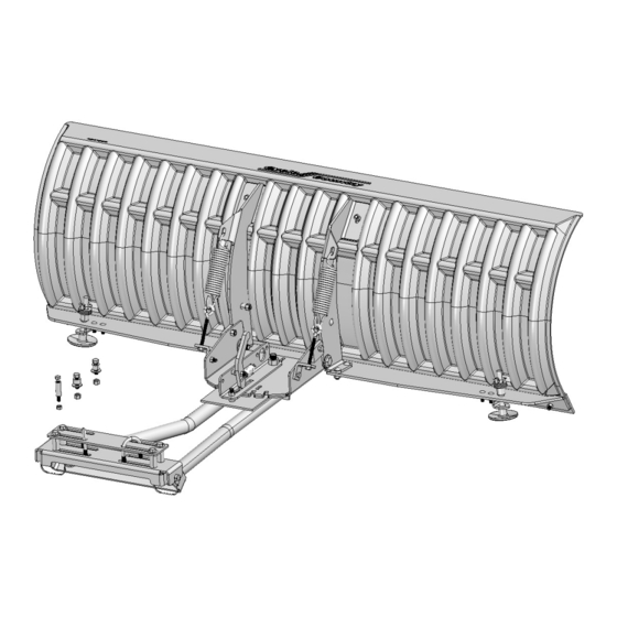
‘Y’ Initial spring ATV FRONT tension setting: With spring attached to blade support, thread locknut onto the eyebolt until spring coils begin to open slightly INCORRECT © 2011 Cycle Country Accessories Corporation... - Page 7 4. Place the blade assembly on its back and attach the wear bar, item #37, blade support using fasteners Illustration 3. Torque to specification after all fasteners have been installed. WEAR BAR FASTENER TORQUE: 17ft. lbs. (23 Nm) ILL. 1C © 2011 Cycle Country Accessories Corporation...
- Page 8 Set the skids even with the wear bar cutting edge for level surfaces such as concrete or asphalt. For irregular surfaces, lower the skids to raise the wear bar cutting edge. ILL. 1E © 2011 Cycle Country Accessories Corporation...
- Page 9 NOTICE 2C - Install Lever Spring, Item #11 ILL. 2 2. Place hinge pivot bracket, Item #14, onto the push tube, Item #1, as shown in Illustration 3. ILL. 3 © 2011 Cycle Country Accessories Corporation...
- Page 10 50 ft. lbs. (67.7 Nm) ILL. 5 2. Install the blade stops, Item #5. Fasten with bolts, Item #15 and nuts, Item #6. See Illustration 6. Do not torque fasteners at this time. ILL. 6 © 2011 Cycle Country Accessories Corporation...
- Page 11 Blade position should be vertical for best performance ILL. 9 BLADE STOP ADJUSTMENT 6. Tighten the blade pivot fasteners to specification once the desired stop position is determined. FASTENER TORQUE: 17ft. lbs. (23 Nm) © 2011 Cycle Country Accessories Corporation...
- Page 12 All transportation costs incurred submitting product to Cycle Country for warranty consideration must be borne by the purchaser. If Cycle Country determines that the product must be returned to the factory for credit, please call 1-800-841-2222 for a Return Merchandise Authorization (RMA) number and shipping instructions.
Need help?
Do you have a question about the BEARFORCE 10-0490 and is the answer not in the manual?
Questions and answers