
Related Manuals for Sime FORCED 200


Summary of Contents for Sime FORCED 200
- Page 1 SIME FORCED 200 - 300 SyStèmeS SolaireS à circulation forcée Solar Kit forceD Draft SiStemi Solari a circolaZione forZata SiStemaS SolareS De circulaciÓn forZaDa Documentation Dpt. Sime - cod. 7500341 - 10/2015...
-
Page 2: Table Of Contents
ANTIFREEZE..............................45 THERMOSTATIC.MIxING.vALvE........................45 SOLAR.ExPANSION.vESSEL..........................45 REQUIREMENTS.AND.PRE-INSTALLATION.OF.THE.SOLAR.COLLECTORS..........46 INSTALLATION.OF.THE.SOLAR.COLLECTORS....................49 CHARGING.THE.SYSTEM..........................53 CONFIGURATION.OF.THE.SOLAR.CONTROL.PANEL..................55 MAINTENANCE..............................56 TROUBLESHOOTING............................57 DISPOSING.OF.THE.SOLAR.SYSTEM........................58 GENERAL.CONDITIONS............................58 Fonderie Sime SpA reserves the right to amend all of the product and relative accessories specifications without prior warning. -
Page 3: Preface
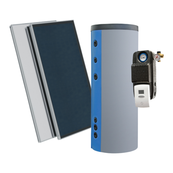
PREFACE The.SIME FORCED.circulation.manifolds.must.be.installed.by.authorised.professional.installers,.who.must.fully.comply. with.the.hydraulic.and.electric.layouts. To.guarantee.correct.installation,.they.must.follow.the.indications.provided.with.each.component.(eg:.solar.collectors,. mounting.frame,.control.panel,.boiler,.solar.unit,.etc.). The.SIME FORCED.circulation.collectors.can.be.installed.according.to.three.different.solutions.for.groups.of.1.to.6.people,. and.they.come.with.the.following.components: –.. Sime FORCED 200 code 8501812 . 1.Sime.Plano.182.Collector.code.8500011 . 1.BS.2S.200.Domestic.Hot.Water.Boiler.code.8106812 . 1.Single-column.solar.hydraulic.unit.(with.Termosolis.control.unit).code.8501223 . 1.Expansion.vessel.bracket.code.6317055A . 1.Expansion.vessel.flexible.tube.code.6317056 . 1.Protection.module.for.the.overvoltage.control.unit.code.8106123 . 1.ø.1/2”.L..95.probe-holder.code.6317047 . 1.Collector.connection.kit.code.8500300 . 1.18-litre.expansion.vessel.code.8106070 . 1.10.kg.Antifreeze.tank.code.8106094 . 1.Chassis.code.8501700 . 1.Thermostatic.mixing.valve.code.8106097 . 1.Documentation.kit.code.5800343 –.. -
Page 4: Forced.circulation.systems
FORCED CIRCULATION SYSTEMS Nowadays,.production.and.energy.savings.without.contaminating.the.environment.is.extremely.important..The.conven- tional.energy.sources.of.the.planet.are.declining.to.a.threatening.level,.as.our.society.requires.an.increasing.amount.of. energy;.as.a.result,.pollution.is.affecting.the.climate.balance. On.the.other.hand,.the.Renewable.Energy.Sources.can.be.a.solution.for.both.the.energy.and.environmental.problem..The. international.legislation.is.gradually.modifying.and.encouraging,.even.imposing,.the.use.of.alternative.energy.products. with.the.aim.of.meeting.the.energy.requirement.without.placing.the.environment.at.risk. DOMESTIC HOT WATER DEMAND It.was.statistically.calculated.that.the.average.daily.consumption.of.a.family.varies.from.35-50.litres.per.person..Should. we.add.the.consumption.of.the.washing.machine.and.dishwasher.in.case.they.were.connected.to.the.solar.system,.around. 20.litres.are.required.daily.for.each.appliance.(for.one.wash). A.family.made.up.of.four.people.with.an.average.DHW.consumption.of.40.litres.per.person,.requires.a.160-litre.solar. system...The.requirement.increases.by.at.least.40.litres.per.day.if.we.add.the.domestic.appliances.connected.to.the.solar. system..To.obtain.the.maximum.benefit.from.the.solar.water.heater,.use.the.highest.amount.of.hot.water.possible.during. the.day.so.that.the.plant.can.continuously.produce.during.the.sunny.period,.maintaining.yield.to.a.maximum. GENERAL INSTALLATION RULES Installation must be conform to the local standards in force for hydraulic and electric plants:.Remove.the.solar.system. packaging. in. the. place. of. installation. to. protect. the. equipment. against. impacts. during. transport,. avoiding. resting. the. collectors'.weight.on.the.pipes.connection.fittings..The.collectors'.crystals.must.remain.covered.until.installation.is.com- pleted,.until.the.boiler.is.filled.with.domestic.water.to.avoid.the.filling.liquid.from.boiling.or.the.crystals.from.breaking..Do. -
Page 5: Technical.features.of.the."Sime.plano".Collector
TECHNICAL FEATURES OF THE "SIME PLANO" COLLECTOR Outer body made.of.aluminium.profile.(Al.Mg.Si.05). Fig..1 Rear cover made.of.galvanized.steel,.0.5.mm.thick,.tightly.fitted.with.an.elastic.EPDM.seal. Pipe grid, whose.number.and.thickness.can.be.adjusted:.Headers.(horizontal).are.punched.with.upper.expansion,.to. ensure.perfect.fitting.of.the.collectors.(vertical).and.to.avoid.pressure.dropping.in.the.collectors..Distance.between. pipes.=.93.mm.(EN.1652). Copper pipe grid: header: Ø 22 supply.and.reaction.of.the.solar.collector..Ø.8.collectors:.thermal-absorption.of.the. 182.-.230.SIME.FLAT.solar.collector. The 0.3 mm thick black sheet aluminium absorber .or.the.0.4.mm.thick.selective.aluminium.absorber.fully.covers. the.surface.of.the.opening.cover.and.the.headers,.thereby.increasing.the.collector's.absorption.capacity..The.collec- tor.is.welded.to.the.pipe.grid.with.LASER.technology(Laser Welded).. High density, environmentally-friendly thermal insulation .obtained.with.a.50.mm.(rear).and.20.mm.(sides).thick-... -
Page 6: Assembly.of.the.solar.collector.chassis
ASSEMBLY OF THE SOLAR COLLECTOR CHASSIS SUPPLY Fig. 3... - Page 7 ASSEMBLY OF THE CHASSIS ON FLAT ROOF CHASSIS WITH 1 OR 2 COLLECTORS 1.. Tighten.part.1.to.part.2.using.the.M8.screws.and.nuts.provided. Repeat.the.operation.for.the.other.coupling. 2.. Tighten.part.3.to.part.2.vertically.. 35° Tighten.diagonal.4.to.part.2.and.tighten.the.bolts. Repeat.steps.1,.2,.and.3.for.the.other.coupling. 4.. Place.part.6.as.indicated.in.the.figure.and.tighten.the.pins. To assemble the solar collectors,.place.the.supporting.section.5.of.the.collector.to.the.lower.part..Place. the.four.washers.(7).between.the.two.parts,.without.tightening.the.M8.pins. Do not use part 5 to mount a solar collector..The.solar.collector.is.fixed.using.the.two.washers.(7),.as. described.in.figures.5a.and.5b...
- Page 8 6.. Repeat.the.operation.for.the.top.part. For.the.two-collector.model,.firstly.place.the.left.one.lifting.the.upper.and.lower.support.part.of.the.col- lector.and.the.washers.(7)..Slightly.tighten.the.M8.screws.and.nuts.with.the.collector.support.parts.when. the.same.collector.is.placed.underneath,.in.order.to.easily.temporary.assemble.and.centre.it.with.the. system... Join.the.second.collector.and.fasten.the.fittings..* 9... Direct.the.solar.collector.and.firmly.tighten.the.base.using.the.4.inserts.and.screws.(M10x60). * Tighten the fittings ONLY. ANY BREAKAGE DUE TO THE TORSION OF THE PIPE BUNDLE IS NOT COVERED BY THE WARRANTY.
- Page 9 ASSEMBLY OF THE CHASSIS ON INCLINED ROOF CHASSIS WITH 1 OR 2 COLLECTORS Tighten.part.1.to.part.2.using.the.M8.screws.and.nuts.provided. Repeat.the.operation.for.the.other.coupling... 2. . Place.horizontal.parts.4.to.the.upper.parts.to.build.the.structure. Tighten.the.right-hand.side.(6).(used.to.support.the.base.to.the.tile).to.the.lower.part.. 35° 3... Place.the.collector.5.support.part.on.the.lower.part,.for.the.two.collector.model;.place.the.four.collector.fixing. washers.(7).between.the.parts.and.tighten.the.M8.screws.with.the.nuts... Part. 5. is. not. required. for. mounting. the.single-collector.model..As.indicated.in.figure.3a,.the.collector.is.fixed.using.the.collector.fixing.washers.(7). 4. .. Repeat.the.operation.for.the.top.part.. 5. . . U se.a.spirit.level.to.fix.the.right-hand.side.of.point.2.to.the.tile.sides.in.order.to.place.them.horizontally. compared.to.the.subsequent.ones. Manually.bend.the.right-hand.side.of.step.2.enclosing.the.sides.of.the.tiles.
- Page 10 For.the.two.collector.model,.firstly.place.the.left.one.lifting.the.upper.and.lower.support.part.of.the.collector.. Slightly.tighten.the.M8.screws.and.nuts.with.the.collector.support.parts.when.the.same.collector.(7).is.placed. underneath,.in.order.to.easily.temporary.assemble.and.centre.it.with.the.system.Position.the.Ø22.fittings.me- chanically.fastened.to.the.collector.edges. Join.the.second.collector.and.tighten.the.fittings..* Position. and. mechanically. fasten. the. Ø22. socket. on. the. top-right. part. and. on. the. bottom-left. part. of. the. collector(s). * Tighten the fittings ONLY. BREAKAGE DUE TO THE TORSION OF THE PIPE BUNDLE IS NOT COVERED BY THE WARRANTY.
-
Page 11: Technical.features.of.the.boiler
TECHNICAL FEATURES OF THE BOILER Install.the.boiler.(refer.to.the.boiler.dimensions.and.connections). ø est. ø int. BS 2S 3000 lt Fig. 4 BS 2S BS 2S BS 2S Dimensional values and hydraulic connections INSPECTION.FLANGE outer.Φ.168.mm/.inner.Φ.114.mm Connection ELECTRIC.HEATER Connection 1”.1/2 THERMOMETER 1384 1411 Connection 1/2” COLD.WATER Connection 1”... -
Page 12: Operation.forced.circulation.systems
Install.a.pressure.reducer,.where.required,.for.the.inlet.domestic.hot.water..Install.a.calibrated.safety.valve.according.to.that. indicated.on.the.data.plate.applied.to.the.storage.tank.and,.in.standard.cases,.install.a.6.BAR.safety.valve.. Install.an.8.bar.safety.valve.on.the.cold.water.inlet.of.the.boiler.in.order.to.protect.the.product.from.excessively.high.pressure.. Place.a.water.pressure.regulator.at.the.mains.water.inlet,.which.must.be.calibrated.at.a.maximum.level.of.4.5.bar,.in.the.event. the.boiler.is.installed.in.an.area.where.the.mains.water.pressure.is.too.high.(on.average.more.than.6.5.bar).. If.the.mains.water.is.too.hard.(20.°F),.install.a.purifying.device,.correctly.calibrated,.in.front.of.the.boiler. Before.commissioning,.we.recommend.making.sure.that.the.flanges.and.the.connections.of.the.removable.coils.are.fastened. correctly.. The.storage.tank.temperature.must.not.exceed.95.°C.to.prevent.damage.to.the.inner.coating. We.recommend.cleaning.inside.the.boiler.every.12.months..Check.the.magnesium.sacrificial.anodes.every.12.months.to.prevent. corrosion..Inspect.where.water.is.particularly.aggressive. OPERATION FORCED CIRCULATION SYSTEMS Forced.circulation.solar.systems.are.used.to.produce.domestic.hot.water..They.constitute.an.ecological.proposal.and.ef- ficient.energy.solution.that.combines.high.results,.autonomy,.design,.easy.installation.and.money.savings;.moreover,.they. reduce.the.consumption.cost.of.the.traditional.energy.sources.considerably. The.system.automations.control.the.temperature.difference.between.the.solar.collectors.and.the.boiler;.in.addition,.they. provide.the.relative.commands.to.ensure.the.continuous.supply.of.hot.water.according.to.the.circuit.regulations. The.differential.thermostat.is.programmed.electrically.to.control.the.thermal.differential.and.is.supplied.with.interface. keys.and.a.screen.to.display.the.parameters.and.messages..Moreover,.it.comes.with: -.Closed.circuit.antifreeze.protection.system. -.Overheating.closed.circuit.protection.system. When.the.temperature.of.the.solar.collector.exceeds.that.of.the.boiler.by.6-10.°C,.the.solar.system.circulator.activates. (thermal.differential.implementation)..The.circulator.stops.the.operation.when.the.temperature.drops.to.20.°C.(hyster- esis)..In.the.event.of.system.inertia,.a.command.can.be.sent.to.an.auxiliary.energy.source.(electric.or.central.heating). All the components required for the connection are included in the packaging. All the components are suitable for the mixture of water and glycol. -
Page 13: Solar.hydraulic.unit
SOLAR HYDRAULIC UNIT 1- 2 SINGLE-COLUMN UNIT (Fig. 6) LED indicator for viewing the pump op- erating status Fig..6 DESCRIPTION OF THE OPERATIONS Installation load (part I - Fig. 7): Intercept.the.flow.by.closing.the.valve.(screwdriver.fitted.horizontally).Introduce.the.fluid.of.tap.A..Wait.for.the.liquid.dis- charge.from.tap.B..Slowly.close.taps.A.and.B. Cleaning the system with water (part I - Fig. 7): Intercept.the.flow.by.closing.valve.v.(screwdriver.fitted.horizontally)..Introduce.the.washing.liquid.of.tap A..Wait.for.the.liquid.discharge.from.tap.B. - Page 14 HIGH EFFICIENCY PUMP CURVE (code 6272328) Pompa ad alta efficienza (cod. 6272328) External control via PWM p/kPa Wilo-Yonos PARA ST 15/7.0 PWM1 PWM2 4660/ ≤5 /≥95 1~230 V - Rp½, Rp 1, Rp 1¼ PWM1 4178/ 15 n=1/min/ % PWM 1 / % PWM 2 PWM2 PWM1 PWM2...
-
Page 15: Solar.control.panel
The.TERMOSOLIS.control.panel.is.provided.as.per.standard.with.the.GI hydraulic unit. TERMOSOLIS CONTROL PANEL TERMOSOLIS.is.a.digital.electronic.device.which.can.be.programmed.to.manage.thermal.solar.plants. The.solution.manages.wholly.the.solar.system.by.checking.the.pumps,.the.eventual.diverter.valve,.the.probes.(PT1000.e. NTC),.a.puffer/boiler.and,.also,.another.secondary.heating.source.. The.integrated.user.interface.is.composed.by.a.backlight.display.and.4.buttons..The.display.shows.the.scheme.of.the. selected.plant.and.the.probes.in.place.with.their.values.and.the.eventual.anomalies,.while.the.buttons.can.switch.on.or. off.the.device.and.program.the.board.functions.. To.assure.the.system.endurance,.when.switched.off,.some.functions.are.kept.on,.as.the.anti-freezing.protection,.the. anti-lock.of.the.pump.and.of.the.diverter.valve. There.are.3.possible.profile.of.the.device,.such.as.Stand.Alone,.in.which.only.TermoSolis.is.present.itself;.communicat- ing.with.a.Sime.Home/Sime.Home.Plus.remote.control,.so.a.remote.control.and.Full.System.manage.the.system;.and. then.the.complete.solution,.which.sees.the.connections.with.other.Sime.devices.to.get.the.whole.control.of.the.heating. and.DHW.plant. TECHNICAL DATA DIMENSIONS GENERAL 108 mm Power supply 230 Vac +10% ÷ -15% 54 mm 54 mm 34 mm Frequency 50Hz +5% ÷... -
Page 16: Antifreeze
Specific.weight.at.15.°C:.1.053 Colour:.Colourless Appearance:.Liquid Boiling.point:.160.°C.at.760.mmHg Water.%.weight:.3.2 Freezing.point.at.50%.in.water:.-34.°C pH.(50%.volume):.9.0 Foam:.ml/s.40/02 Corrosion.resistance.test.with.various.types.of.metals:.excellent.according.to.the.ASTM.D.method.for.resistance.to.hard. water:.Not.precipitated Reserve.Alkalinity:.ml.HCL.0.1.N.. THERMOSTATIC MIxING vALvE The.thermostatic.mixing.valve.(supplied.with.the.forced.circulation.system).is.used.in.systems.for.the.production.of.do- mestic.hot.water. Its.function.is.to.maintain.the.set.temperature.value.of.the.mixed.water,.which.is.sent.to.the.application.when.the.tem- perature.and.the.supply.pressure.of.the.hot.and.cold.inlet.water,.or.of.the.extracted.flow.rate,.vary. The.substance.of.the.domestic.hot.water.contained.in.the.solar.boiler.may.be.at.a.higher.temperature.(eg:.60°C);.there- fore,.in.order.to.prevent.physical.burns,.a.thermostatic.mixing.valve.that.mixes.hot.water.with.cold.water.must.be.installed. in.order.to.reach.an.optimal.service.temperature.(eg.40.°C.-.45.°C). SOLAR ExPANSION vESSEL The.solar.expansion.vessels.must.have.a.nitrile.membrane.as.the. heat-transfer.fluid.that.circulates.inside.the.primary.circuit.is.made. with.water.and.non-toxic.propylene.antifreeze.liquid. The.expansion.vessels.cannot.have.a.butyl.membrane.nor.can.the. heating.tanks.have SBR.membranes,.as.the.antifreeze.liquid.may.damage.them.(as.it.is. a.very.aggressive.substance). The.SIME FORCED circulation.solar.equipment.is.supplied.with.an. 18.L.expansion.vessel.with.nitrile.membrane. Description: 18.L.expansion.vessel.with.a.fixed.nitrile.rubber.membrane.. Flange:.pressed.galvanised.carbon.steel. Max..pressure:.6.bar Fitting:.3/4”... -
Page 17: Requirements.and.pre-Installation.of.the.solar.collectors
REQUIREMENTS AND PRE-INSTALLATION OF THE SOLAR COLLECTORS DIRECTION OF THE SOLAR COLLECTORS To.ensure.optimal.yield,.the.solar.collector.must.face.SOUTHWARDS..A.15-20.°C.deviation.can.be.accepted;.deviations. that.exceed.20°.must.be.compensated.by.using.a.larger.collector. ALMOST.TWICE. ALMOST.TWICE. THE.SURFACE THE.SURFACE INCREASE.OF.THE.SURFACE INCREASE.OF.THE.SURFACE Fig..9 INCLINATION OF THE SOLAR COLLECTORS Half.time (good.compromise) In. order. to. optimise. the. performance,. the. inclination. angle. of. the. collector. must. be. equal.to.the.latitude.of.the.installed.equip- ment. - Page 18 POSITIONING THE SOLAR COLLECTORS The.solar.collectors.can.be.installed.in.various.positions,.on.the.outside.of.the.house.or.around.it,.and.can.have.various. configurations..Make.sure.that.the.collector.receives.the.sun.rays.without.any.interference.from.trees.or.close.build- ings,.even.during.the.worst.conditions.(winter);.otherwise,.compensate.the.lack.of.radiation.by.increasing.the.collector. surface. SOLAR. AREAS. COLLECTORS OF.SHADE Fig..11 In.the.presence.of.various.aligned.solar.collectors,.make.sure.they.do.not.shade.each.other.and.comply.with.the.project. indications.(see.Fig..12)..Before.positioning.the.system,.you.must.be.aware.of.the.local.regulations..In.Italy,.for.example,. except.for.landscape.or.monumental.areas,.it.is.sufficient.to.communicate.the.installation.to.the.authorised.technical. departments. ExAMPLE: Solar.panel SHADE. BETWEEN. ROWS. OF. Pannello solare COLLECTORS.INSTALLED.AT.45°. (CALCULATION.RELATIvE.TO.THE. CITY.OF.vERONA.-.ITALY) 45° 45° Fig..12 DIMENSIONS OF THE SOLAR SYSTEM The.system.dimensions.depend.on.the.consumption.of.hot.water.and.m .heated.by.the.system.at.low.temperature.(only. for.combined.systems). The.choice.depends.on.the.type.of.climate.and.on.the.number.of.family.members,.which.will.affect.the.measurement.of. the.deposit.and.that.of.the.collectors.
- Page 19 How it works (Fig. 13) The.general.operating.principle.of.the.solar.systems.is.the.following:.the.sun.heats.the.heat-transfer.fluid.and.transfers. the.energy.to.the.boiler.by.means.of.the.collector.and.the.support.of.a.pump. In.the.boiler,.the.coil.transfers.the.heat.to.the.domestic.hot.water,.which.warms.up. With.reference.to.the.table.below,.the.TERMOSOLIS.control.panel.with.three.probes.is.used.both.to.activate.the.pump.to. transfer.the.energy.from.the.solar.collectors.to.the.boiler.through.the.fixed.coil,.and,.optionally,.to.activate.the.automatic. motorised.valve.that.deviates.the.flow.of.the.heating.system.boiler.to.the.coil,.for.the.integration.inside.the.boiler. The.control.panel.compares.the.temperature.detected.by.probe.“S1”.in.the.solar.collector.with.that.detected.by.probe. “S2”.located.at.the.bottom.of.the.boiler. When.the.temperature.of.the.collector.exceeds.that.of.the.boiler.considerably,.∆T.inside.the.control.panel.provides.the. signal.to.the.solar.circuit.pump.to.transfer.energy. When.this.does.not.happen,.the.pump.does.not.receive.the.signal.and.the.energy.accumulated.in.the.boiler.is.transferred. to.the.panel.and.will.be.dispersed.. In.this.event,.the.boiler.activates.by.means.of.probe."SB".and.ensures.the.temperature.of.the.domestic.hot.water.. FROM.THE. DA RETE MAINS TO. . ALL’UTILIZZO USAGE FROM. DA RETE THE. MAINS Fig..13...
-
Page 20: Installation.of.the.solar.collectors
ATTENTION: The cold inlet of the “Sime Plano” collectors must be located at the bottom right or at the bottom left of the col- lector coil. The hot outlet must be at the top of the opposite side, ie, if we enter in the bottom left, we must exit from the top... - Page 21 COLD. INLET HOT. OUTLET HOT. OUTLET COLD. INLET HOT. HOT. OUTLET OUTLET COLD. COLD. INLET INLET Fig..14 PIPING AND INSULATION The.pipes.that.connect.the.solar.collector.to.the.boiler.hydraulic.unit.must.be.made.of.copper.or.stainless.steel.(fitted. hose.reel.made.of.AISI.316L.stainless.steel.2x2.insulated).and.must.have.an.outer.diameter.of.10.mm.(no.greater,.no. smaller). The.pipes.must.never.be.made.of.galvanised.steel.due.to.galvanic.currents.and.incompatibility.problems.with.the.an- tifreeze. liquid;. moreover,. they. must. never. be. multi-layers. for. problems. related. to. the. high. temperature. that. can. be. reached.
- Page 22 be.any.points.where.the.pipes.go.upwards.to.prevent.the.formation.of.air.pockets.and,.as.a.result,.malfunctions. In.the.event."Cusps".are.required.for.structural.reasons,.you.must.install.bleed.valves.either.on.the.flow.or.return. SOLAR.COLLECTORS COLLETTORE SOLARE CUSPIDE CUSPS SOLAR. GRUPPO DI REGULATION REGOLAZIONE UNIT SOLARE ALLO TO..SOLAR.HEAT. SCAMBIATORE ExCHANGER SOLARE...
- Page 23 SOLAR ExPANSION vESSELS The.expansion.vessels.must.have.suitable.dimensions.to.contain.additional.volumes.of.the.mixture.of.water.-.antifreeze. liquid.generated.from.thermal.expansion.and.vapour,.which.can.be.checked.in.the.collector..The.membranes.of.the.ex- pansion.vessels.must.be.suitable.for.the.maximum.discharge.pressure.supplied.by.the.safety.valves.(6.bar).and.must.be. resistant.to.the.mixture.of.water.and.antifreeze.liquid.(heat-transfer.fluid). Check.that.the.pre-charge.pressure.of.the.expansion.vessel.is.approximately.0.3.bar.lower.than.the.cold.water.filling. pressure.of.the.system. THERMOSTATIC MIxING vALvE The.thermostatic.mixing.valve.must.be.installed.on.the.boiler.outlet.before.the.water.reaches.the.application.(in.order.to. prevent.scalding),.according.to.that.indicated.in.the.attached.power.supply.diagram. To.ensure.correct.mixing,.the.hot.water.circuit.and.the.cold.water.circuit.must.have.the.same.pressure. MIXING VALVE MISCELATORE MIXING VALVE MISCELATORE DOMESTIC. ACQUA TO.THE. ALL’UTILIZZO HOT. CALDA MIxED.USE WATER MISCELATA SANITARIA TO.THE. BOLLITORE ALL’UTILIZZO BOILER MIxED.USE SOLARE ACQUA FREDDA SANITARIA DALLA RETE DOMESTIC.
-
Page 24: Charging.the.system
CHARGING THE SYSTEM CLEANING THE SOLAR CIRCUIT To.clean.and.fill.the.solar.circuit,.use.the.two.taps.of.the.solar.unit,.one.set.for.filling.and.the.other.one.for.discharge,. separated.by.a.shut-off.valve..To.improve.operation,.place.the.solar.unit.taps.on.the.lowest.point.of.the.system..Optionally,. install.a.3rd.tap.in.the.lowest.part.of.the.system.to.fully.discharge.the.system. Before.filling.the.system.with.the.mixture.of.water.and.antifreeze.liquid,.rinse.it.making.water.circulate..This.way,.the. processing.waste.of.the.solar.circuit.is.removed. –. Open.the.tap.(A).and.connect.it.to.the.cold.water.tap.using.a.rubber.pipe. –. Open.the.tap.(B).and.connect.it.to.a.water.discharge.tap.using.a.rubber.pipe. –. Close.the.shut-off.valve.(v). –. Close.all.the.shut-off.taps.before.closing.the.automatic.bleed.valves.or.all.the. manual.bleed.valves. –. Open.the.water.tap.and.leave.the.water.to.run.hard.in.the.solar.circuit.for.a.few.minutes.. –. If.this.operation.is.performed.when.there.is.a.risk.of.frost,.pay.special.attention.to.the.back.drain.of.the.collector.in. order.to.prevent.the.formation.of.frost.and.breaking.the.panel. In.the.event.that.the.collectors.do.not.run.for.long.periods,.we.recommend.disconnecting.them.from.the.system.to.make. air.flow.inside.and.covering.them.using.a.shading.sheet.to.prevent.them.from.overheating.. (Fig. 1) LOAD DRAIN (Fig. 2) (Fig. 3) - Page 25 CHECKING THE SEAL Complete.the.rinsing.phase.by.closing.the.tap.(B).and.let.the.pressure.increase.inside.the.solar.system.until. a.pressure.0.2.bar.below.that.of.the.safety.valve.is.reached.(eg,.if.the.safety.valve.is.6.bar,.try.with.5.8.bar).. Close.the.tap.(A).and.then.the.water.tap. Open.the.shut-off.tap.(v)..Configure.the.solar.circuit.pump.operation.in.the.control.unit,.open.the.shut-off.taps. of.the.bleed.valves.and.release.the.air.from.the.solar.circuit.manually: –..on.the.roof,.remove.the.cover.of.the.bleed.valve.and.and.press.using.the.tip.of.a.screwdriver; –..on.the.thermal.system,.through.the.exhaust.gas.of.the.solar.unit. Check.the.pressure.and,.if.required,.reset.by.opening.the.tap.(A).and.the.water.tap. visually.check.all.the.pipes.and.fittings.and.make.sure.there.are.no.leaks..Leave.the.system.under.pressure. for.a.time.to.verify.whether.the.pressure.decreases. During.a.trial.period,.the.system.can.run.only.with.water.to.verify.the.presence.of.possible.leaks,.if.there.is. not.risk.of.frost. New.systems.may.freeze.because.the.owner.bought.the.antifreeze.liquid.but.did.not.add.it.the.system..To. avoid.these.problems,.make.sure.that.the.antifreeze.liquid.has.been.poured.into.the.system. BLEEDING THE SOLAR CIRCUIT Connect.both.taps.to.a.cube.using.a.rubber.pipe.to.discharge.and.drain.the.system..The.amount.of.water.can. be.measured.and.used.to.prepare.the.mixture.of.water.and.glycol..To.ensure.drainage,.the.bleeding.valves. must.be.open.to.make.the.air.enter.and,.if.required,.press.using.the.screwdriver.to.facilitate.the.operation. Make.sure.that.the.water.filled.in.the.circuit.is.discharged.from.the.system.to.prevent.it.from.freezing.or.from. damaging.the.panel. FILLING THE SOLAR CIRCUIT Before.filling.the.circuit,.check.the.pre-charge.pressure.of.the.expansion.vessel.using.a.pressure.gauge.or. bike.pump.having.a.pressure.approximately.0.3.bar.below.the.cold.water.filling.pressure.of.the.system. If.you.plan.to.use.the.antifreeze.liquid,.mix.water.and.glycol.inside.a.container.before.pouring.it.into.the.sys- tem..The.percentage.of.glycol.depends.on.the.minimum.temperature.that.can.be.reached.in.the.area.where. the.system.is.installed.(it.is.obtained.from.the.stored.data.related.to.the.minimum.temperature.of.the.area).. This.temperature.must.be.reduced.by.at.least.10°C.so.as.to.allow.the.panel.to.cool.down.to.about..6-7°C.above. ambient.temperature. To be sure, integrate the antifreeze liquid until you reach 40% of the volume of the total mixture (not lower, regardless of the protection rating, to achieve an effective inhibitory function against pipe corrosion).
-
Page 26: Configuration.of.the.solar.control.panel
–. Connect.a.filling.pump.using.the.rubber.pipes.(for.example,.the.manual.filling.pump.code.8106095.optional,.or.a.system. test.pump).to.the.container.and.tap.(A). –..Take.the.rubber.pipe.of.tap.(B)..back.to.the.container. –..The.taps.must.remain.open.and.the.shut-off.valve.(v).must.remain.closed. –..Open.all.the.shut-off.taps.in.front.of.the.automatic.and.manual.bleed.valves. –..The.manifold.circuit.must.be.filled.using.the.pump.with.the.mixture.of.water.and.glycol,.until.the.fluid.starts.leaking. from.the.tap.(B). –..Close.the.tap.(B)..The.pressure.inside.the.solar.circuit.must.be.released.until.the.desired.initial.pressure.is.reached.. Now,.close.tap.(A).and.stop.filling. -. Open.the.shut-off.tap.(v). –..Activate.the.solar.circuit.pump.setting.it.in.continuous.operation.to.remove.the.air.from.the.circuit..Manually.open.the. bleed.valve.many.times.pressing.with.the.tip.of.a.screwdriver..Release.the.air.from.the.pump.by.opening.the.large.cop- per.screw.in.front.of.the.pump..Release.the.air.from.the.gas.extractor..Adjust.the.valve.(v).so.it.has.a.flow.rate.of.45/50. l/h.per.m2.of.the.inlet.surface. –. After.a.few.days.and.once.you.have.fully.released.the.air.(no.noise.is.heard.inside.the.system),.close.the.shut-off.valves. in.front.of.the.bleed.valves.in.order.to.prevent.the.discharge.of.possible.vapours.inside.the.collector.from.the.valve. –. Once.again,.check.the.initial.pressure.inside.the.solar.circuit.when.it.is.still.cold.(early.in.the.morning).and,.if.required,. add.new.fluid. –. If.there.is.still.no.fluid,.apply.the.insulation.on.the.pipes.of.the.solar.circuit,.joining.all.points.(or.glueing.them).without. leaving.leaks. Solar.hydraulic.unit Degassifier. Filling.pump lower.coil Mixture.of.water. and.antifreeze. liquid.at.40% CONFIGURATION OF THE SOLAR CONTROL PANEL Check.that.all.the.probes.and.electric.devices.required.for.system.operation.are.connected.properly. Fasten.the.control.panel.according.to.the.system.configuration.described.in.the.instruction.manual.provided.with.the. control.panel. -
Page 27: Maintenance
MAINTENANCE The.forced.circulation.systems.by.SIME FORCED.are.extremely.reliable.and.require.minimum.maintenance.during.the. year..Comply.with.the.following.instructions:. WHEN WHAT TO DO Make sure that the percentage of antifreeze liquid in the mixture is below the freezing point; it can be added. Make sure that the pH of the water and antifreeze liquid mixture exceeds 8. -
Page 28: Troubleshooting
TROUBLESHOOTING 1.. The.system.does.not.heat.or.does.not.heat.well. . 6..High.temperature.of.the.collectors.during.the.night 2.. The.pump.makes.a.noise. 7..Strong.pressure.changes. 3.. Decrease.of.the.system.pressure. 8..The.water.in.the.boiler.cools.down.considerably.during.the.night 4.. Leak.in.the.safety.valve. 9..High.temperature.in.the.solar.collectors 5... Display.of.incorrect.values.in.the.control.unit SOLUTION PROBLEM/CAUSE PROBLEMA/CAUSA SOLUZIONE When.the.system.is.in.hot.mode,.drain. Air.in.the.system Con impianto a caldo, sfiatare la valvo- Aria nell’impianto the.air.bleed.valve.of.the.collectors.and. la di sfogo aria sui collettori e il dega- gas.extractor.in.the.solar.unit..Repeat. -
Page 29: Disposing.of.the.solar.system
DISPOSING OF THE SOLAR SYSTEM The.solar.system.consists.of.the.following.components: SOLAR COLLECTOR it.can.be.disposed.of.by.separating.the.main.components: Metal.parts.(aluminium.or.stainless.steel.casing,.copper.capturing.surface,.brass.fittings); Covering.glass.slab; Insulation.(mineral.wool.sheet,.CFC-free.polyurethane.foam); Rear.polypropylene.closing.sheet.(black).or.made.of.PvC.(white). SOLAR BOILER it.can.be.disposed.of.by.separating.the.main.components: Metal.parts.(boiler.body,.magnesium.anode,.and.protection.device.if.made.of.stainless.steel); Insulation.(CFC-free.rigid.polyurethane.foam); leatherette.coating.(only.for.vertical.boilers). SOLAR UNIT It.can.be.disposed.of.by.separating.its.main.components: The.pump.is.made.of.cast.iron.metallic.parts.(pump.body),.copper.(windings),.steel.(shaft).and.reinforced.. resins.(impeller); Metal.parts.(steel.and.brass.fittings); Insulation.(40g/l.black,.EPP.thermoformed) TERMOSOLIS REGULATION CONTROL UNIT it.can.be.disposed.of.by.separating.the.main.components: Plastic.parts.(the.outer.half.and.the.transparent.cover); Electrical.parts. PIPING They.can.be.disposed.of.by.separating.the.main.components: Copper.or.stainless.steel.piping; Expanded.elastomer.insulation. COLLECTOR SUPPORTING FRAME The.supporting.frame.is.made.of.aluminium. - Page 30 Fonderie Sime S.p.A. Via.Garbo,.27.-.37045.Legnago.(VR).Italy. Tel..+39.0442.631111.-.Fax.+39.0442.631291 www.sime.it.-.info@sime.it...
Need help?
Do you have a question about the FORCED 200 and is the answer not in the manual?
Questions and answers