Table of Contents
Advertisement
Quick Links
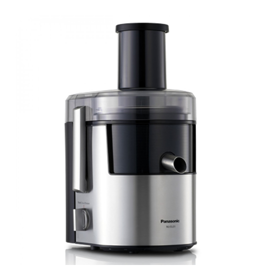
MJ-DJ31SRA-VN
Model No.
MJ-DJ31SSD-HK
MJ-DJ31SSL-MY
MJ-DJ31SSP-SG
MJ-DJ31SST-AU
MJ-DJ31SST-NZ
MJ-DJ31STN-AE
MJ-DJ31STN-OM
MJ-DJ31STN-QA
MJ-DJ31STQ-KZ
MJ-DJ31STQ-RU
MJ-DJ31STQ-UR
MJ-DJ31STZ-AE
MJ-DJ31STZ-KW
MJ-DJ31STZ-SA
Destination :
HONGKONG, VIETNAM, SINGAPORE,
MALAYSIA, AUSTRALIA, NEW
ZEALAND, SAUDI ARABIA, UAE,
KUWAIT, OMAN, QATAR, KAZAKH-
STAN, RUSSIA, UKRAINE
© 2014 Panasonic Manufacturing Malaysia Berhad
(6100-K). Unauthorized copying and distribution is a
violation of law.
PMMA140921CE
Juicer/Blender
Advertisement
Table of Contents

Related Manuals for Panasonic MJ-DJ31SRA-VN


Summary of Contents for Panasonic MJ-DJ31SRA-VN
- Page 1 MJ-DJ31STQ-RU MJ-DJ31STQ-UR MJ-DJ31STZ-AE MJ-DJ31STZ-KW MJ-DJ31STZ-SA Destination : HONGKONG, VIETNAM, SINGAPORE, MALAYSIA, AUSTRALIA, NEW ZEALAND, SAUDI ARABIA, UAE, KUWAIT, OMAN, QATAR, KAZAKH- STAN, RUSSIA, UKRAINE © 2014 Panasonic Manufacturing Malaysia Berhad (6100-K). Unauthorized copying and distribution is a violation of law.
-
Page 2: Table Of Contents
TABLE OF CONTENTS PAGE PAGE 1 Specifications ------------------------------------------------------3 2 Schematic Diagram-----------------------------------------------3 2.1. With EMC ----------------------------------------------------3 2.2. Without EMC ------------------------------------------------4 3 Basic Wiring Diagram -------------------------------------------4 4 Troubleshooting Guide------------------------------------------5 4.1. The Juicer commons --------------------------------------5 4.2. The Juicer ----------------------------------------------------5 5 Disassembly Instructions --------------------------------------7 5.1. -
Page 3: Specifications
1 Specifications MODEL MJ-DJ31SSD-HK MJ-DJ31SRA-VN, MJ-DJ31SSL-MY, MJ- DJ31SSP-SG, MJ-DJ31SST-AU, MJ-DJ31SST- NZ, MJ-DJ31STN-AE, MJ-DJ31STN-OM, MJ- DJ31STN-QA, MJ-DJ31STQ-KZ, MJ-DJ31STQ- RU, MJ-DJ31STQ-UR, MJ-DJ31STZ-AE, MJ- DJ31STZ-KW, MJ-DJ31STZ-SA Power supply 220 V ~ 50-60 Hz 220 V - 240 V ~ 50-60 Hz Power consumption... -
Page 4: Without Emc
2.2. Without EMC 3 Basic Wiring Diagram... -
Page 5: Troubleshooting Guide
4 Troubleshooting Guide 4.1. The Juicer commons 4.1.1. SYMPTOM : Motor doesn’t rotate 4.1.2. SYMPTOM : Motor “roars” but doesn’t rotate. (Turn the switch off immediately) 4.1.3. SYMPTOM : Motor overheats 4.1.4. SYMPTOM : Unusual odor 4.2. The Juicer 4.2.1. SYMPTOM : Motor “roars”... - Page 6 4.2.4. SYMPTOM : Juice is poorly extracted 4.2.5. SYMPTOM : Juice contains too much residue 4.2.6. SYMPTOM : Cutter rubs against inlet bottom 4.2.7. SYMPTOM : Leakage of juice...
-
Page 7: Disassembly Instructions
5 Disassembly Instructions 5.1. Disassembly Procudere Step 3 Unscrew 2 screws from Cord Holder. Step 4 Detach Connector. Step 1 Unscrew 4 screws from Bottom Plate. Step 5 Detach Connectors. Step 2 Remove Power Knob A Assy. Step 6 Detach Connector. Step 7 Remove Switch Assy. - Page 8 Step 8 Release Clip. Step 11 Hold Connector Complete. Step 9 Release Rod. Step 12 Unscrew with screwdriver. Step 10 Unscrew 2 screws. Step 13 Remove Connector Complete.
- Page 9 Step 14 Release Catches. Step 15 Remove Juicer Attachment Rib. Step 16 Unscrew 4 screws. Step 17 Remove Motor Ass’y.
-
Page 10: Clearance Adjustment (Fig.3)
5.2. Clearance Adjustment (Fig.3) 1. Insert the clearance gauge between the upper cutter surface of spinner (extractor)and the bottom of feader opening. (Fig.3) 2. When the thinner side (1/51" ... 0.5mm) can be inserted and the thicker side (1/28" ... 0.9mm) cannot, the clearance is appro- priate. -
Page 11: Glass Container And Cutting Blade (Fig.4, 5, 6)
5.3. Glass Container and Cutting Blade (Fig.4, 5, 6) 1. Remove the cover, then turn the glass container up-sidedown. 2. Secure the glass cup and turn the mounting ring counterclockwise. (Fig.4) 3. The gasket (upper) can be removed. 4. Wrap the cutting blade with a cloth for protection and secure it. 5. -
Page 12: Mill Container And Mill Cutter (Fig.7, 8, 9)
5.4. Mill Container and Mill Cutter (Fig.7, 8, 9) 1. Remove the cover, then turn the mill container up-sidedown. 2. Secure the glass cup and turn the mounting ring counterclockwise. (Fig.7) 3. Wrap the cutting blade with a cloth for protection and secure it. 4. -
Page 13: Exploded View And Replacement Parts List
6 Exploded View and Replacement Parts List 6.1. Exploded View Plug A2 Plug C2... -
Page 14: Replacement Parts List
6.2. Replacement Parts List Safety Ref. No. Part No. Part Name & Description Remarks REPLACEMENT PARTS LIST AJD58-151-K0 PLUNGER UNIT AJD89P1512K0 CONTAINER LID UNIT MALAYSIA AJJ12-1511 STAR SHAPE SCREW AJA04-154 SPINNER COMPLETE AJD98P1515K0 CONTAINER ASSY AJD87-151-K0 JUICE CUP COVER UNIT AJD05-1511X0 JUICE CUP AJD05-154-X0... - Page 15 Safety Ref. No. Part No. Part Name & Description Remarks AX61BL5000 MILL CUP (GLASS) AVE44-180-X0 INNER LID AVE02-1802K0 OUTER LID AX03BR6300 CUP (GLASS) AX05B83100 GASKET (UPPER) AX95BG5200 CUTTING BLADE UNIT AMX13B45100 WAVING WASHER AMX27B69200L SHAFT WASHER B AVE87-2195K0 MOUTING RING SUB ASS'Y AVE18-1802 SLIDE PIECE SPRING AVE17-2191X1...
Need help?
Do you have a question about the MJ-DJ31SRA-VN and is the answer not in the manual?
Questions and answers