
Related Manuals for Druck PACE5000


Summary of Contents for Druck PACE5000
- Page 1 PACE5000 / 6000 Pressure Automated Calibration Equipment Instruction Manual Druck.com...
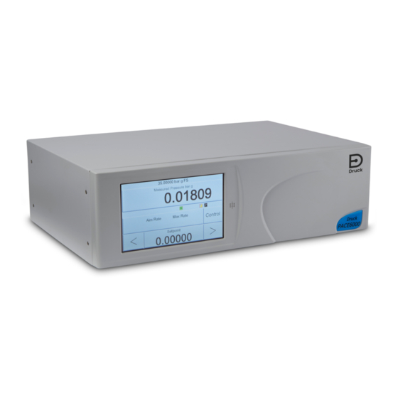
- Page 3 Introduction The PACE5000/6000 are pneumatic pressure controllers. The PACE5000 contains one pressure control module. The PACE6000 can contain up to two independent pressure control modules. The color touch-screen displays the measured pressure and the status of the instrument. The touch-screen enables selections and settings to be changed. The instrument can be operated remotely through communication interfaces.
- Page 4 Do not dispose of this product as household waste. Use an approved organization that collects and/or recycles waste electrical and electronic equipment. For more information, contact one of these: - Our customer service department: Druck.com - Your local government office. WARNING Turn off the source pressure(s) and carefully vent the pressure lines before disconnecting or connecting the pressure lines.
- Page 5 Digital Pressure Instrument etc. And so on e.g. For example Foot Gauge GPIB General purpose interface bus Water Mercury Hertz IDOS Intelligent Digital Output Sensor (Druck product) i.e. That is Copyright 2008 Baker Hughes Company. English–PACE5000/6000 Instruction Manual | iii...
- Page 6 Unit Under Test Volts °C Degrees Celsius °F Degrees Fahrenheit Associated Publications The following table lists the Druck publications referenced in this manual: Publication Title K0447 PACE 5000/6000 User Guide and Safety Instructions K0476 Pressure Control Module User Guide and Safety Instructions...
-
Page 7: Table Of Contents
Measure and Control Modes 3.5.3 Task 3.5.4 Divider 3.5.5 Divider Menu Structure 3.5.6 Preset Global Setup Selections 3.6.1 Status Area Settings Barometric Reference Option Supervisor Setup Instrument Status 3.9.1 Software Copyright 2008 Baker Hughes Company. English–PACE5000/6000 Instruction Manual | v... - Page 8 Task 6.3.4 Units 6.3.5 Global Setup 6.3.6 Setup Zero Control Setup 6.4.1 Vent 6.4.2 Nudge 6.4.3 Set-point Limits 6.4.4 Slew Rate 6.4.5 Control Mode 6.4.6 Active Control 6.4.7 Passive Control Copyright 2008 Baker Hughes Company. vi | PACE5000/6000 Instruction Manual–English...
- Page 9 6.15.7 Control of Aeronautical Parameters 6.16 Analog Output Option 6.17 Volts-free Contact Option 6.18 Burst Pressure Testing Option 6.18.1 Selecting Burst Pressure Task 6.18.2 Test Parameter Entry 6.18.3 Example Burst Pressure Test Copyright 2008 Baker Hughes Company. English–PACE5000/6000 Instruction Manual | vii...
- Page 10 6.22 Return Goods/Material Procedure 6.22.1 Safety Precautions 6.23 Packaging Procedure 6.24 Vacuum System Parts Appendix A. Pressure Units and Conversion Factors Appendix B. Air Density Appendix C. User Interface Icons Copyright 2008 Baker Hughes Company. viii | PACE5000/6000 Instruction Manual–English...
-
Page 11: Description
Introduction 1. Description 1.1 Introduction The PACE5000 single-channel and PACE6000 single/dual-channel, Pressure Automated Calibration Equipment measures and controls pneumatic pressures and displays, on a touch- screen, the pressure measurement and controller status. The touch-screen enables selections and settings in both measure and control modes. The instrument can be operated remotely through communication interfaces. - Page 12 Chapter 1. Description Figure 1-3: PACE5000 Rear View Figure 1-4: PACE6000 Rear View Options available are detailed in the product Data Sheet. For information and notes on applications, refer to Section 6, “Reference,” on page 43 or Druck.com Copyright 2008 Baker Hughes Company.
-
Page 13: Installation
INFORMATION After unpacking a cold instrument, allow time for it to stabilize and any condensation to evaporate. Check that the PACE5000/6000 packaging contains the following: PACE5000 or PACE6000 Pressure Controller. Power supply cable. Safety instructions, instruction manual and CD-ROM containing the full documentation suite. -
Page 14: Pressure Adaptors
ISO 228 G1/8 Male to AN6 37° Male. IO-ADAPT-BARB ISO 228 G1/8 Male to 1/4 Hose. IO-ADAPT-G1/4 ISO 228 G1/8 Male to ISO 228 G1/4 Female. IO-ADAPT-G1/8 ISO 228 G1/8 Male to ISO 228 G1/8 Female. Copyright 2008 Baker Hughes Company. 4 | PACE5000/6000 Instruction Manual–English... -
Page 15: Pressure Connection
Refer to Figure 2-2 for connection to the PACE pressure connectors. 1 PACE pressure connector. 2 Bonded seal. 3 ISO228/1 G1/8 pressure connector. 4 NPT thread pressure connector. 5 Pressure adaptor, see Section 2.4.1. Figure 2-2: PACE Pressure Connection Copyright 2008 Baker Hughes Company. English–PACE5000/6000 Instruction Manual | 5... -
Page 16: Connecting To Uut
The instrument requires a positive pressure supply. Instruments operating in an absolute range or negative pressure range require a vacuum supply. A vacuum supply should be used for a fast response for instruments operating near atmospheric pressure. Copyright 2008 Baker Hughes Company. 6 | PACE5000/6000 Instruction Manual–English... -
Page 17: Supply Equipment
During system pressure vent operations, the pressure discharges from the system to atmosphere through the negative and vent ports. Pipe both ports to a safe discharge area or fit a diffuser to the negative port. Copyright 2008 Baker Hughes Company. English–PACE5000/6000 Instruction Manual | 7... -
Page 18: Pneumatic Connection Examples
Optional differential connection 14 Manual external vent valves Atmosphere Figure 2-5: Pneumatic Connections without Vacuum Supply Note: Refer to Section 6, “Reference,” on page 43 for details of other system components. Copyright 2008 Baker Hughes Company. 8 | PACE5000/6000 Instruction Manual–English... - Page 19 Mount near to the PACE CM -ve port to exhaust most of the high pressure gas directly to atmosphere. The vacuum buffer volume needs to be rated to at least the highest system pressure. Note: Section 6, “Reference,” on page 43 for details of other system components. Copyright 2008 Baker Hughes Company. English–PACE5000/6000 Instruction Manual | 9...
-
Page 20: Rack-Mount Option
There must be enough space at the rear of the instrument for all the cables and pipes (tubes). The length of the cables and pipes (tubes) must allow for the removal and installation of the Copyright 2008 Baker Hughes Company. 10 | PACE5000/6000 Instruction Manual–English... - Page 21 10. Secure the instrument in the equipment rack with two of the screws and washers (supplied). 11. Remove the two spigots* and replace with the remaining two screws and washers (supplied). Copyright 2008 Baker Hughes Company. English–PACE5000/6000 Instruction Manual | 11...
-
Page 22: Power Connection
2.9.1 Pressure Control Module DC Power and Logic Input Connectors DC power output Logic (Switch) input The DC power output is rated at 24 V DC, 100 mA. An internal self-resetting fuse protects the output. Copyright 2008 Baker Hughes Company. 12 | PACE5000/6000 Instruction Manual–English... -
Page 23: Communication Connection
2.10.1 RS-232 Interface When using the RS-232 interface, a cable must be connected directly from the instrument to a suitable port on the computer in a ‘point to point’ link. Copyright 2008 Baker Hughes Company. English–PACE5000/6000 Instruction Manual | 13... -
Page 24: Ieee 488 Interface
Connect the other end of the connector/cable assembly to the IEEE 488 connector on the controller/computer. Change the IEEE 488 communication parameters. Refer to Section 6.9.4.2, “IEEE 488,” on page 50. Copyright 2008 Baker Hughes Company. 14 | PACE5000/6000 Instruction Manual–English... - Page 25 Repeat this procedure for all the instruments in the system. Use the Supervisor setup (communications) menu on each instrument to setup the required communication parameters. Refer to Section 6.9.4.2, “IEEE 488,” on page 50. Copyright 2008 Baker Hughes Company. English–PACE5000/6000 Instruction Manual | 15...
- Page 26 Chapter 2. Installation Figure 2-11: IEEE 488 Connection Copyright 2008 Baker Hughes Company. 16 | PACE5000/6000 Instruction Manual–English...
-
Page 27: Operation
The instrument is now ready for use. Note: PACE 6000 shows a single display by default. This is the left hand pressure control module. Change to dual display in Global Setup/Display menu. Copyright 2008 Baker Hughes Company. English–PACE5000/6000 Instruction Manual | 17... - Page 28 Chapter 3. Operation Measure setup Control/measure selection Nudge up Set-point entry Status (touch to enter control setup) Nudge down Figure 3-1: Touch Screen Areas Copyright 2008 Baker Hughes Company. 18 | PACE5000/6000 Instruction Manual–English...
-
Page 29: Measure Mode
Reference level difference Control mode with no Timed zero (gas head correction) overshoot Control mode active Filter pressure reading Tare enabled Control mode passive Linear rate Zero Control mode gauge Maximum rate Copyright 2008 Baker Hughes Company. English–PACE5000/6000 Instruction Manual | 19... -
Page 30: Auto-Range
With both controllers in Measure mode, if a set-point within the range of the lower ranged controller is entered and Control is then selected the lower ranged controller controls to the entered set-point. Copyright 2008 Baker Hughes Company. 20 | PACE5000/6000 Instruction Manual–English... -
Page 31: Controller Off - Decreasing Set-Point
OUTLET VENT SUPPLY OUTLET VENT PACE6000 instrument Pressure output Pressure Pressure regulator regulator Pressure source 3.4 Control Mode In measure mode, press and the instrument changes to control mode. Control Copyright 2008 Baker Hughes Company. English–PACE5000/6000 Instruction Manual | 21... -
Page 32: Controlling To A New Set-Point
To save the new set-point, touch the set-point area of the screen. This returns the display to the measured pressure screen and showing the new set-point. Copyright 2008 Baker Hughes Company. 22 | PACE5000/6000 Instruction Manual–English... -
Page 33: Effort Meter
The display shows the pressure value changing as the instrument controls to the new set- point, at the set rate of change. When the display shows ambient or zero pressure, press the key to switch off the Measure controller and return to measure mode. Copyright 2008 Baker Hughes Company. English–PACE5000/6000 Instruction Manual | 23... -
Page 34: Operation And Example Procedures
Switch the instrument ON, the display shows measured pressure mode (except when regulator mode is selected) and the task set before the power-off. 3.5.2 Measure and Control Modes The instrument operates in the two modes that follow: Copyright 2008 Baker Hughes Company. 24 | PACE5000/6000 Instruction Manual–English... -
Page 35: Task
The screen display changes as follows: • The current pressure reading changes from black to blue. • If enabled, the effort meter indicates the amount of work done (effort) by the controller. Copyright 2008 Baker Hughes Company. English–PACE5000/6000 Instruction Manual | 25... -
Page 36: Divider
Divider Divider Divide as set-up. Start control mode. Divider parameters High Set-point Set-point Number of points Example: High set-point = 2 bar Low set-point = 0 bar Copyright 2008 Baker Hughes Company. 26 | PACE5000/6000 Instruction Manual–English... -
Page 37: Preset
After setting all the 25 preset pressures, enter control mode. Press a soft key to change to the pressure assigned to that key (and * controlled at the selected rate). Preset Preset Preset as set-up Set-up Value Copyright 2008 Baker Hughes Company. English–PACE5000/6000 Instruction Manual | 27... -
Page 38: Global Setup Selections
Pressing Global Setup from measure or control setup menu changes the touch-screen display to show the following selections: • Supervisor Setup • Calibration • Save/Recall User Setup • Display Selections Escape Key Copyright 2008 Baker Hughes Company. 28 | PACE5000/6000 Instruction Manual–English... -
Page 39: Status Area Settings
Displays barometric pressure. Tare Indicates tare condition and value. Analog Output Shown if option is installed. P1 - P2 Displays Module 1 pressure minus Module 2 pressure (P2 - P1). Copyright 2008 Baker Hughes Company. English–PACE5000/6000 Instruction Manual | 29... -
Page 40: Barometric Reference Option
(measured by the barometric sensor). Refer to Section 6.10, “Option Enable Process,” on page 58 and the Data Sheet for the performance of barometric reference and precision of absolute ranges. Copyright 2008 Baker Hughes Company. 30 | PACE5000/6000 Instruction Manual–English... -
Page 41: Supervisor Setup
User defined units User defined units - user unit 1 Enter the equivalent value in Pascals Instrument alias name Language More next page: Restore last settings Restore previous defaults Y/N? Copyright 2008 Baker Hughes Company. English–PACE5000/6000 Instruction Manual | 31... -
Page 42: Instrument Status
Zero Current set-up In Limits High Alarm Low Alarm Slew Rate Power Up PACE5000 Operation time* Use log Control time* * days, hours and minutes More next page: Use log Copyright 2008 Baker Hughes Company. 32 | PACE5000/6000 Instruction Manual–English... -
Page 43: Software
Analogue O/P Boot ROM VFC Main Code VFC Boot ROM Exit set-up. Module (2) Main Code Next page of menu options. Loops from last page to first Module (2) Boot ROM page. Copyright 2008 Baker Hughes Company. English–PACE5000/6000 Instruction Manual | 33... - Page 44 Chapter 3. Operation Copyright 2008 Baker Hughes Company. 34 | PACE5000/6000 Instruction Manual–English...
-
Page 45: Maintenance
Do a standard serviceability test Section 5.2, “Standard Serviceability Test,” on page 41. 4.5 Software Update To update the PACE5000 / PACE6000 internal software, use the following procedure: Insert a USB memory device into an internet connected PC. Open Windows Explorer and select the USB memory device root folder. Delete the following... - Page 46 16. Once the software updates have been completed, turn off the PACE. 17. Turn the power back on to the PACE. 18. Wait until PACE displays the pressure measurement screen. 19. Verify the installed software version against the software history document. Copyright 2008 Baker Hughes Company. 36 | PACE5000/6000 Instruction Manual–English...
-
Page 47: Replacement Parts
Refer to Figure 4-1. Set the power switch to OFF. If the PACE is not rack-mounted, got to step 3. For access to rack-mounted instruments, the following actions maybe required: Isolate pneumatic supplies. Copyright 2008 Baker Hughes Company. English–PACE5000/6000 Instruction Manual | 37... -
Page 48: Pressure Control Module Filters
Remove the pressure control module to access to the filters. Use a 5 mm hexagonal key, to release the filter retainer (1). Remove the five filters (2). If necessary, invert the pressure control module to aid removal. Copyright 2008 Baker Hughes Company. 38 | PACE5000/6000 Instruction Manual–English... -
Page 49: Pressure Control Module Replacement
Fit a fully compatible pressure control module (1) into the instrument case (2). Secure the four cross-head screws (drive size 2) securing the pressure control module in the instrument case. Copyright 2008 Baker Hughes Company. English–PACE5000/6000 Instruction Manual | 39... - Page 50 Chapter 4. Maintenance Copyright 2008 Baker Hughes Company. 40 | PACE5000/6000 Instruction Manual–English...
-
Page 51: Testing And Fault Finding
PACE controller. Select vent and the pressure reduces to atmospheric pressure at a controlled rate (vent rate). The test is completed when the controller is at atmospheric pressure. Note: Copyright 2008 Baker Hughes Company. English–PACE5000/6000 Instruction Manual | 41... -
Page 52: Fault Finding
If the controller status characterized. indicator is outside the tolerance band. 5.4 Approved Service Agents For the list of service centers: Druck.com Copyright 2008 Baker Hughes Company. 42 | PACE5000/6000 Instruction Manual–English... -
Page 53: Reference
Oil must be completely removed as this causes a rapid deterioration of the control valve performance. Copyright 2008 Baker Hughes Company. English–PACE5000/6000 Instruction Manual | 43... -
Page 54: Systems Without A Negative Supply
6.2.1 Negative or Vacuum Supply The negative supply for absolute control does not need to be regulated. Any variation between this and absolute zero will affect instrument operation if controlling at low absolute pressures. Copyright 2008 Baker Hughes Company. 44 | PACE5000/6000 Instruction Manual–English... -
Page 55: Oil Contamination
The instrument measures pressure relative to the pressure at the reference port. An atmospheric pressure change causes the indicator to adjust the displayed pressure. This appears as instability. To keep a stable displayed pressure, the reference port should be Copyright 2008 Baker Hughes Company. English–PACE5000/6000 Instruction Manual | 45... -
Page 56: Measure Setup
Refer to Section 6.8, “Global Setup,” on page 48. 6.3.6 Setup Zero Setup zero has the following configuration: Option Description Mode Off, Auto, Timed Interval 00.00.00 (hours.minutes.seconds) Isolation status Isolated, Non-isolated Copyright 2008 Baker Hughes Company. 46 | PACE5000/6000 Instruction Manual–English... -
Page 57: Control Setup
6.5 Global Setup PIN protected menu. Refer to Section 6.9, “Supervisor Setup,” on page 49. Copyright 2008 Baker Hughes Company. English–PACE5000/6000 Instruction Manual | 47... -
Page 58: Status
PIN protected menu. Refer to Section 6.9, “Supervisor Setup,” on page 49. 6.8.3 Save/Recall user setup. Save user setup. Recall user setup. 6.8.4 Display Resolution Backlight Audio volume Status area. Screen mode (PACE 6000 only). Copyright 2008 Baker Hughes Company. 48 | PACE5000/6000 Instruction Manual–English... -
Page 59: Supervisor Setup
RS-232 point-to-point only. Daisy chain is not supported. Baud Rate Power-up Default 9600, no parity, handshake = Xon/Xoff 2400, 4800, 9600, 19k2, 38k4, 57k6, 115k2 Baud Rates Selectable Parity None, Odd, Even Flow Control None, Hardware, Xon/Xoff Copyright 2008 Baker Hughes Company. English–PACE5000/6000 Instruction Manual | 49... - Page 60 A firewall protects the Ethernet connection. The firewall is always turned on. Table 6-4 details the PACE open Ethernet ports. Table 6-4: Open Ethernet Ports Ethernet Port 80/tcp PACE Web server (http). 111/tcp rpcbind (RPC for VXI). 111/udp rpcbind (RPC for VXI). Copyright 2008 Baker Hughes Company. 50 | PACE5000/6000 Instruction Manual–English...
- Page 61 Touch any of the three horizontal Measure touch pads on the home screen to open the CONTROL SETUP screen On the CONTROL SETUP screen, select GLOBAL SETUP. Select SUPERVISOR SETUP. Copyright 2008 Baker Hughes Company. English–PACE5000/6000 Instruction Manual | 51...
- Page 62 Note: The factory set Supervisor PIN is 0268. If the Supervisor PIN has been locally changed, make sure that the new PIN is kept in a safe place. If the new PIN is lost, it can only be reset at a Druck Service Centre. Press COMMUNICATIONS STATUS to open the COMMUNICATIONS STATUS screen.
- Page 63 On the ETHERNET PARAMETER screen, use the UP and DOWN arrows on the right of the screen to highlight the HOST NAME field. Press the top touch pad on the screen to enter the HOST NAME screen. Copyright 2008 Baker Hughes Company. English–PACE5000/6000 Instruction Manual | 53...
- Page 64 On the ETHERNET PARAMETER screen, use the UP and DOWN arrows on the right of the screen to highlight the RESET LAN SETTINGS field. Press the RESET THE LAN SETTINGS touch pad on the top touch pad of the screen. Copyright 2008 Baker Hughes Company. 54 | PACE5000/6000 Instruction Manual–English...
- Page 65 USB ‘A’ connector, the internal memory SD card becomes unaccessible. Note: When upgrading software, make sure that the USB ‘B’ connection is disconnected. To configure the USB connection: Copyright 2008 Baker Hughes Company. English–PACE5000/6000 Instruction Manual | 55...
-
Page 66: Timeout
Note: Confirmation of the new PIN permanently replaces the old PIN. Record this new PIN and keep in a safe place. If new PIN is lost it can only be reset by returning the instrument to a Druck service center. -
Page 67: Instrument Alias Name
Create a language file by translating from the English language file. Check the pixel width of each translated word by using the PACE language check file. This can be downloaded from the Druck Support Central. Create an empty DPI folder on a USB stick. -
Page 68: Restore As Shipped Settings
Touch the top Measure area of the screen. Select Global Setup. Select Calibration. Enter a Calibration PIN 1234. Enter new option key xxxxxxxxxx (10 digits). After entry of this key PACE confirms the options have been enabled. Copyright 2008 Baker Hughes Company. 58 | PACE5000/6000 Instruction Manual–English... -
Page 69: Leak Test Option
At the start of the test, the instrument applies a test pressure to the user system. A control dwell time allows the user system to thermally stabilize. The instrument changes to measured mode and then records the pressure change during measure dwell time. On Copyright 2008 Baker Hughes Company. English–PACE5000/6000 Instruction Manual | 59... - Page 70 TP 1 Control Measure Dwell Dwell Pressure Control Measure Dwell Dwell TP 2 Leak Pressure Time (seconds) TP Test pressure Copyright 2008 Baker Hughes Company. 60 | PACE5000/6000 Instruction Manual–English...
-
Page 71: Switch Test Option
If necessary, this can be an external DC source. Common mode must be kept within 30 V maximum. 6.12.1 Start Controls pressure at a fast slew rate to a set-point just below expected switch operating point. De-bounce time can be increased for slower test slew rates. Copyright 2008 Baker Hughes Company. English–PACE5000/6000 Instruction Manual | 61... -
Page 72: Test
Test program Start Stop Single step Start/Stop Test Program Create/Edit Select a test program from list Copy <...new...> File name Copy Exit Delete Delete Edit Copyright 2008 Baker Hughes Company. 62 | PACE5000/6000 Instruction Manual–English... -
Page 73: Creating A Test Program
Counter 1 - Used in a loop to count the number of loop cycles. (Legacy count). COUNT 2 Counter 2 - Used in a loop to count the number of loop cycles. DWELL Specifies dwell time (seconds) within the test program. Copyright 2008 Baker Hughes Company. English–PACE5000/6000 Instruction Manual | 63... - Page 74 Allows control of VFC 2: R1, R2, R3 (When VFC is set to Test program under VFC setup). WAIT IN-LIMITS Waits until pressure is within the limits. ZERO Output zeroed Copyright 2008 Baker Hughes Company. 64 | PACE5000/6000 Instruction Manual–English...
-
Page 75: Example Program
Set In-Limits band RESOLUTION Display resolution, 5 digits SETTLING No overshoot TEXT Operator instruction, e.g.”Connect UUT” ZERO SET POINT Set-point, 400 mbar CONTROL Controller ON WAIT IN LIMITS Wait for In-Limits condition Copyright 2008 Baker Hughes Company. English–PACE5000/6000 Instruction Manual | 65... -
Page 76: Programming Loops
Sets the In-Limits band IN LIMITS TIME 10 (00:00:10) seconds SETTLING NO No overshoot OVERSHOOT TEXT Operator instruction, e.g.“Connect UUT” ZERO Performs a sensor zero SET POINT Set-point, 400 mbar Copyright 2008 Baker Hughes Company. 66 | PACE5000/6000 Instruction Manual–English... -
Page 77: Barometric Reference Option
When installed, this option allows absolute or gauge pressure range selection. To obtain absolute pressure the instrument uses a summation of gauge pressure and barometric pressure (measured by the barometric sensor). Copyright 2008 Baker Hughes Company. English–PACE5000/6000 Instruction Manual | 67... - Page 78 Chapter 6. Reference Copyright 2008 Baker Hughes Company. 68 | PACE5000/6000 Instruction Manual–English...
-
Page 79: Zeroing The Reference Sensor
Enter the Calibration PIN and press ENTER CALIBRATION PIN. Use the back arrow in the top right corner of the screen to delete any incorrect data entries. Note: The factory set Calibration PIN is 4321. Copyright 2008 Baker Hughes Company. English–PACE5000/6000 Instruction Manual | 69... - Page 80 A pressure zero is only accepted under the following condition: Reference Sensor reading (vented) Barometric Sensor reading – 2000 ppm FS (0.2% FS) Copyright 2008 Baker Hughes Company. 70 | PACE5000/6000 Instruction Manual–English...
-
Page 81: Aeronautical Option
Aeronautical Option If this condition is not met, the following ZERO OUTSIDE LIMITS error is shown. Note: A zero outside limits error may indicate that the reference sensor is faulty. Contact a Druck Service Centre for assistance. Refer to Data Sheet for the barometric reference and precision of absolute ranges. -
Page 82: Example Of Altitude And Airspeed Testing
The units can be either the aeronautical or pressure units. The units can be changed any time between pressure and pressure converted to aeronautical units. The display shows the output Copyright 2008 Baker Hughes Company. 72 | PACE5000/6000 Instruction Manual–English... -
Page 83: Reference Pressure
Figure 6-3: Q Code Visualization 6.15.6 Go to Ground Returns the instrument and any UUT, connected to it, safely to ground pressure at a controlled rate. Based on tables from ICAO Standard Atmosphere 1964. Copyright 2008 Baker Hughes Company. English–PACE5000/6000 Instruction Manual | 73... -
Page 84: Control Of Aeronautical Parameters
The aeronautical control is an integrated controller. The two modules work together as a dual channel pressure controller Figure 6-4. In aeronautical mode, the display goes to the last selected parameter: • Altitude • Airspeed • Mach Figure 6-4: Screen Layout Copyright 2008 Baker Hughes Company. 74 | PACE5000/6000 Instruction Manual–English... - Page 85 Note: The altitude and airspeed controllers are still actively ON, but held at the selected range. Figure 6-7: Set-points Select 1 (Resume) in Figure 6-7 to continue to the altitude and speed set-points. Copyright 2008 Baker Hughes Company. English–PACE5000/6000 Instruction Manual | 75...
-
Page 86: Analog Output Option
(not used) +24 V dc output, 100 mA max (not used) Switch In 1 (not used) Switch In 2 (not used) Analog output + (not used) Analog output - (not used) Copyright 2008 Baker Hughes Company. 76 | PACE5000/6000 Instruction Manual–English... -
Page 87: Volts-Free Contact Option
The test Copyright 2008 Baker Hughes Company. English–PACE5000/6000 Instruction Manual | 77... -
Page 88: Selecting Burst Pressure Task
Start slew rate, a default value of 10% full-scale can be changed to another value suitable for the device under test. Fast slew rate allowing a fast approach to near the burst area. End set-point, to take the pressure past the expected burst point. Copyright 2008 Baker Hughes Company. 78 | PACE5000/6000 Instruction Manual–English... - Page 89 User selected set-point near the expected burst point. Start slew rate default value 10% full-scale/second. User selected set-point of the expected burst point. End slew rate default value 1% full-scale/second. Copyright 2008 Baker Hughes Company. English–PACE5000/6000 Instruction Manual | 79...
-
Page 90: Example Burst Pressure Test
Item Description +ve source zero -ve source zero Sensor correction Selects the range for a three-point calibration routine. Valve correction Source PDCR correction Three-point calibration of both source pressure sensors. Copyright 2008 Baker Hughes Company. 80 | PACE5000/6000 Instruction Manual–English... -
Page 91: Communications - Instrument Emulation
Service by unauthorized sources will affect the warranty and may not guarantee further performance. You must inform Druck if the product has been in contact with any hazardous or toxic substance. The relevant COSHH or in the USA, MSDS, references and precautions to be taken when handling. -
Page 92: Vacuum System Parts
NW10 Clamping Ring C105-11-398 NW10 Centering Ring C105-14-401 NW25 Clamping Ring C105-14-398 NW25 Centering Ring C105-12-349 NW16/10 Centering Ring C105-01-103 NW16 to ¼NPT Male Adapter, S/S FL-20-K FL20K Foreline Trap Copyright 2008 Baker Hughes Company. 82 | PACE5000/6000 Instruction Manual–English... -
Page 93: Appendix A. Pressure Units And Conversion Factors
To convert from pressure VALUE 1 in pressure UNITS 1, to pressure VALUE 2 in pressure UNITS 2, calculate as follows: FACTOR 1 ---------------------------- - VALUE 2 VALUE 1 FACTOR 2 Copyright 2008 Baker Hughes Company. English–PACE5000/6000 Instruction Manual | 83... - Page 94 Appendix A. Pressure Units and Conversion Factors Copyright 2008 Baker Hughes Company. 84 | PACE5000/6000 Instruction Manual–English...
-
Page 95: Appendix B. Air Density
1.210 1.201 1.193 1.259 1.249 1.240 1.231 1.222 1.213 1.204 1.271 1.261 1.252 1.243 1.234 1.225 1.216 1.283 1.274 1.264 1.255 1.246 1.237 1.228 a. 100 kPa = 1 bar. Copyright 2008 Baker Hughes Company. English–PACE5000/6000 Instruction Manual | 85... - Page 96 Appendix B. Air Density Copyright 2008 Baker Hughes Company. 86 | PACE5000/6000 Instruction Manual–English...
-
Page 97: Appendix C. User Interface Icons
Date & time Delete Diagnostic analog output Diagnostic barometric Diagnostic control sensor Diagnostic controller option Diagnostic general Diagnostic RS-232 Diagnostic source sensor Diagnostic vacuum Diagnostic volt-free Diagnostics sensor Display Divider Error Copyright 2008 Baker Hughes Company. English–PACE5000/6000 Instruction Manual | 87... - Page 98 Passive mode Percentage Power-up Preset Pressure Pressure filter Process Protective vent Question Range Recall user setup Reset use log Resolution Re-try Roughing RS-232 Restore to as shipped Restore settings 2 settings Copyright 2008 Baker Hughes Company. 88 | PACE5000/6000 Instruction Manual–English...
- Page 99 Test program delete Timing Time out Timed zero Units User defined units Use log Use log history Vent Vent time out Vent Yes/No Vent setup Warning Zero analog output Zero history Zero Copyright 2008 Baker Hughes Company. English–PACE5000/6000 Instruction Manual | 89...
- Page 100 Appendix C. User Interface Icons Copyright 2008 Baker Hughes Company. 90 | PACE5000/6000 Instruction Manual–English...
- Page 102 India Japan Toulouse Pune Tokyo +33 562 888 250 +91-2135-620421~425 +81 3 3531 8711 sensing.FR.cc@bakerhughes.com mcindia.inhouseservice@bakerhughes.com service.druck.jp@bakerhughes.com Abu Dhabi Leicester Billerica +971 2 4079381 +44 (0) 116 2317107 +1 (281) 542-3650 ...
Need help?
Do you have a question about the PACE5000 and is the answer not in the manual?
Questions and answers