Table of Contents
Advertisement
Quick Links
Advertisement
Table of Contents

Related Manuals for Punair TIG 315P AC/DC


Summary of Contents for Punair TIG 315P AC/DC
- Page 1 OWNER'S MANUAL TIG 315/400P AC/DC...
-
Page 2: Table Of Contents
CONTENTS 1. Contents····················································································································· 1 2. Safety warning············································································································ 2 3. Machine description ··································································································· 3 4. Technical parameters table··························································································· 4 5. Panel function instruction···························································································· 5 6. Installation instruction································································································· 7 7. Operation instruction··································································································· 8 8. Notes or preventive measures ····················································································· 10 9. Maintenance················································································································11 10. -
Page 3: Safety Warning
SAFETY WARNING! In the process of welding or cutting, there will be possibility of injury, so please take protection measure during operation. For more details please review the Operator Safety Guide, which complies with the preventive requirements of the manufacturer. Electric shock——May lead to death !... -
Page 4: Machine Description
MACHINE DESCRIPTION The welding machine is a rectifier adopting the most advanced inverter technology. The development of inverter gas-shielded welding equipment profits from the development of the inverter power supply theory and components. Inverter gas-shielded welding power source utilizes high-power component MOSFET to transfer 50/60Hz frequency up to 100 KHz, then reduce the voltage and commutate, and output high-power voltage via PWM technology. -
Page 5: Technical Parameters Table
TECHNICAL PARAMETERS TABLE Model TIG 315P AC/DC TIG315P AC/DC TIG 400P AC/DC Parameters 3ph AC380V±15% 3ph AC415V±15% 3ph AC380V±15% Power voltage (V) 50/60 50/60 50/60 Frequency (Hz) 12.5 Rated input current (A) 58.7 No-load voltage (V) 10-315 10-315 10-400 Output current adjustment (A) 22.6... -
Page 6: Panel Function Instruction
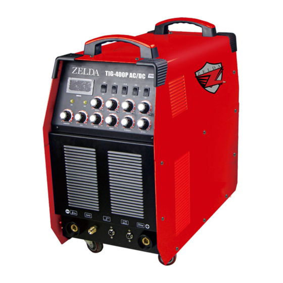
PANEL FUNCTION INSTRUCTION TIG 315P AC/DC FRONT PANEL INSTRUCTION: Current meter Over heat indicator Panel/remote control altering switch Over current indicator AC/DC altering switch Start current adjustment TIG/MMA altering switch Current up slope time adjustment Frequency altering switch Duty ratio adjustment... - Page 7 TIG 400P AC/DC FRONT PANEL INSTRUCTION: OWNER’S MANUAL PNR-YF-05Y-A1...
-
Page 8: Installation Instruction
INSTALLATION INSTRUCTION 1. Make good connection of shielded gas source. Gas supply passage includes cylinder, argon decompressing flow meter and pipe. Connecting part of pipe should use hoop or other things to fasten, in case lest argon leaks out and air gets in. 2. -
Page 9: Operation Instruction
Warning: Any connection operations should be done at the condition that the power has been cut off. The correct sequence is to connect the electrode holder and the earth clamp to the welder well first, then put the electric plug into the socket . OPERATION INSTRUCTION A. - Page 10 down position, no basic value current). 9. Press torch switch and electromagnetic valve starts, you will hear the sound of electricity-releasing HF sparkle and at the same time, argon comes out from the torch. 10. Keep 2-4mm space between tungsten pole and working plate, and press torch control switch, then between electrode and work piece HF electricity is released;...
-
Page 11: Notes Or Preventive Measures
C. MMA welding 1. Turn on power switch; digital current meter is lit; fan begins to wheel. 2. Put the welding switch to “ Down position”, at this time, “Pulse choosing switch”, “2T/4T switch”, “AC/DC switch” are out of work, only welding current knob can use. 3. -
Page 12: Maintenance
2) Do not over load! The operator should remember to watch the max duty current (Response to the selected duty cycle). Keep welding current is not exceed max duty cycle current. Over-load current will damage and burn up machine. 3) No over voltage! Power voltage can be found in diagram of main technical data. -
Page 13: Questions To Be Run Into During Welding
WARNING Blind experiment and careless repair may lead to more problems and make formal check and repair more difficult. When the machine is electrified, the bared parts are with life-threatening voltage. Any direct and indirect touch will cause electric shock, and severe electric shock will lead to death. Warning Connecting the welder directly with the electric generator will damage the maintenance due to the over-voltage pulse. -
Page 14: Troubleshooting And Fault Finding
C. Output current not to rated value: When power voltage departs from the rated value, it will make the output current not matched with rated value; When voltage is lower than rated value, the max output may lower than rated value. D. -
Page 15: Machine Explosion Diagram
1. The high voltage transformer has been hit through or not. 2. The MOSFET is damaged. Abnormal indicator is lit, power The Fast Rectifying Diode is damaged. indicator is lit, fan is working The control board has a fault. The feedback circuits is in fault. (Contact with dealer or manufacturer). 1. -
Page 16: Machine Component List
MACHINE COMPONENT LIST TIG400PAC/DC: OWNER’S MANUAL -15- PNR-YF-05Y-A1... - Page 17 NAME Quantity/set 序号 Carbon film resistor Enamel cover resistor Polyester capacitance Frequency transformer Frequency transformer Reactance implement Three-phase diode bridge Light emitting diode Thermo-sensitive switch Electrical shunt Ship form switch Gas switch Last front-panel Descend front-panel Left side panel Right side panel Bottom Top panel Partition board...
- Page 18 Angled switch Control panel brace board Triangle brace board(left) Triangle brace board(right) Reactance implement support Radiator Radiator Radiator Radiator Radiator Heat transfer board Digital meter Fan net Solenoid valve 2"artificial rubber fix tyre 2"artificial rubber direct tyre Self-locking fastening Knob Handle holder Torch switch socket Torch switch socket...
Need help?
Do you have a question about the TIG 315P AC/DC and is the answer not in the manual?
Questions and answers