Table of Contents
Advertisement
Quick Links
Please file and use this supplement manual together with the service manual for Model No.KX-FP701CX/
KX-FP702CX, Order No.KMF0708102CE.
TABLE OF CONTENTS
1 REPLACEMENT PARTS LIST--------------------------------- 2
1.1. REFERENCE CHART------------------------------------ 2
LISTS --------------------------------------------------------- 2
2 CORRECTION------------------------------------------------------ 3
2.1. Block Diagram---------------------------------------------- 3
2.2. Sensors and Switches------------------------------------ 4
2.3. Program Mode Table ------------------------------------- 5
2.4. Power Supply Board Section --------------------------- 6
2.5. Check the Cover Open Sensor (SW502)------------ 8
Locations ---------------------------------------------------- 8
3 CHANGES----------------------------------------------------------- 9
3.1. Power Supply Board Parts ------------------------------ 9
4 ADDITIONS --------------------------------------------------------10
4.1. Service Function Table ----------------------------------10
4.2. Program Mode Table ------------------------------------10
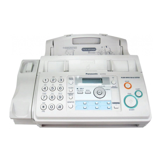
Plain Paper Fax with Copier
Model No.
(for Asia and Middle Near East)
PAGE
© 2008 Panasonic Communications Co., Ltd. All
rights reserved. Unauthorized copying and distribu-
tion is a violation of law.
ORDER NO. KMF0801403SE
KX-FP701CX
KX-FP702CX
Advertisement
Table of Contents

Related Manuals for Panasonic KX-FP701CX


Summary of Contents for Panasonic KX-FP701CX
-
Page 1: Table Of Contents
Plain Paper Fax with Copier KX-FP701CX Model No. KX-FP702CX (for Asia and Middle Near East) Please file and use this supplement manual together with the service manual for Model No.KX-FP701CX/ KX-FP702CX, Order No.KMF0708102CE. TABLE OF CONTENTS PAGE 1 REPLACEMENT PARTS LIST--------------------------------- 2 1.1. -
Page 2: Replacement Parts List
PFHR1715Z PFHR1715Y GUIDE, HOLDER HEAD/L B to C PFHR1716Z PFHR1716Y GUIDE, HOLDER HEAD/R B to C DIGITAL BOARD PARTS (for KX-FP701CX) PFWIFP701CX PFWIFP701CX1 IC (ROM) (Change 1) A to B [Program Ver. GB21CN → GB21CP] PFWIFP701CX1 PFWIFP701CX2 IC (ROM) (Change 2) [Program Ver. -
Page 3: Correction
KX-FP702CX/KX-FP702CX 2 CORRECTION 2.1. Block Diagram [Changed from original section “6.3.1. Block Diagram”]... -
Page 4: Sensors And Switches
KX-FP702CX/KX-FP702CX 2.2. Sensors and Switches [Changed from original section “6.5. Sensors and Switches”]... -
Page 5: Program Mode Table
KX-FP702CX/KX-FP702CX 2.3. Program Mode Table [Changed from original section “12.4.2. Program Mode Table”]... -
Page 6: Power Supply Board Section
KX-FP702CX/KX-FP702CX 2.4. Power Supply Board Section [Changed from original section “12.5.7.2. Troubleshooting Flow Chart”]... - Page 7 KX-FP702CX/KX-FP702CX [Added into original section “12.5.7. Power Supply Board Section”]...
-
Page 8: Check The Cover Open Sensor (Sw502)
KX-FP702CX/KX-FP702CX 2.5. Check the Cover Open Sensor (SW502) [Changed from original section “12.5.9.3. Check the Cover Open Sensor (SW502)”] 2.6. Maintenance Check Items/Component Locations [Changed from original section “15.1.2. Maintenance Check Items/Component Locations”]... -
Page 9: Changes
KX-FP702CX/KX-FP702CX 3 CHANGES 3.1. Power Supply Board Parts [Changed from original section “20.2.5. Power Supply Board Parts”]... -
Page 10: Additions
KX-FP702CX/KX-FP702CX 4 ADDITIONS 4.1. Service Function Table [Added into original section “11.1.3. Service Function Table”] 4.2. Program Mode Table [Added into original section “12.4.2. Program Mode Table”] K.T. KXFP701CX KXFP702CX...
Need help?
Do you have a question about the KX-FP701CX and is the answer not in the manual?
Questions and answers