
Related Manuals for Burford 2200M


Summary of Contents for Burford 2200M
- Page 1 Smart Tyer 2200M/2300M ® Copyright © 2017 by Burford Corp. Second Edition, Date: September/2015 Manual Part No. Serial #...
-
Page 2: Safety Precautions
SAFETY PRECAUTIONS As Burford ® Corp. strives to promote safety in the maintenance and operation of Burford ® equipment; we request that the following safety procedures be followed, along with any additional safety procedures set by the customer’s in-plant safety officers or local codes. -
Page 3: Disclaimer
Burford equipment should only be used for the purpose for which it was sold, and should ® not be modified in any way without notifying the General Manager of Burford Corp. in writing of the modification. The original language for this document is English. Translations to other languages may... -
Page 4: Table Of Contents
CONTENTS SAFETY PRECAUTIONS DISCLAIMER CHAPTER 1: INTRODUCTION Specifications Models Conveyor Requirements Bag Neck Length Requirements Unit Overview E-Stop Location CHAPTER 2: KEY COMPONENTS Tyer Head Needle Twister Hook Holder / Shear Holder / Shear, cont’d. Holder / Shear, cont’d. Bag Switch Package Recognition System Ribbon Guide Gathering Belts... - Page 5 CONTENTS Ribbon Tension Assembly Ribbon Tension Spring Brake Dancer Arm Ribbon Drop Sensor Locking Pin Gathering Brush Adjustment Knob Pressure Regulator Operator Display Optional Key Components Package Detection Sensor Speed Follower Encoder Stand Conveyor CHAPTER 3: INSTALLATION PROCEDURES Mechanical Installation Mechanical Installation, cont’d.
- Page 6 CONTENTS Package Recognition System Dual Ribbon Spool System Package Detection System (PDS) Speed Following Feature General Operation Timing Start Up Procedures Start Up Procedures, cont’d. Operator controls Main power disconnect Audible alarm Changing and threading the ribbon Changing and threading the ribbon, cont’d. CHAPTER 5: SETTINGS AND ADJUSTMENTS Proximity Sensor Adjustment Proximity Sensor Locations...
- Page 7 CHAPTER 6: COMMUNICATIONS Communicating With The Controller General Communications programs ® Burford TERMINAL program Terminal program in Microsoft Windows version 3.0 or 3.1 Configuring the Microsoft Windows terminal program Configuring the Microsoft Windows terminal program, cont’d Cable between PC and tyer head...
- Page 8 HOME command DISPENSE command DISPENSE command, cont’d. + command Capturing data into a text file on the PC ® With the Burford TERMINAL program With Windows TERMINAL program After the files have been captured CHAPTER 7: TROUBLESHOOTING Diagnostic LED's Diagnostic LED's, cont'd.
- Page 9 CONTENTS Semi-Annual Annual 18 Months Pass Thru Shelf Pass Thru Shelf, cont’d. PROM Replacement Procedure PROM Replacement Procedure, cont'd. PROM Replacement Procedure, cont'd. CHAPTER 9: TEST PROCEDURES Test procedure for motor encoders Test procedure for motor continuity Test procedure for servo motor fuses Test procedure for checking the proximity switch LED’s Test procedure for the BCD switch Test procedure for the bag switch...
- Page 11 Chapter 1 Introduction...
- Page 12 ® The Burford 2200M/2300M Series Electronic Smart Tyer is designed to close plastic bags with twist tie ribbon in a wide variety of automatic packaging applications. The tyer uses a microprocessor to control and coordinate the motion of four servo motors, which perform the twist tying function.
-
Page 13: Chapter 1: Introduction
Introduction Specifications ELECTRICAL 110 V , 50/60 H , 1 Φ, 15 A 220 V , 50/60 H , 1 Φ, 15 A 220 V , 50/60 H , 3 Φ, 15 A 380/460 V , 50/60 H , 1 Φ, 15 A 380/460 V , 50/60 H , 3 Φ, 15 A... -
Page 14: Conveyor Requirements
Chapter 1 Conveyor Requirements Depending on conveyor speed and flight spacing, the Smart Tyer is capable of operating speeds of up to 100 packages per minute. The Smart Tyer operates on a nominal 110 Volts, 60 Hz, single-phase alternating current. 15 amp service is recommended. Smart Tyer connections for bagger interlock and safety circuits are provided standard. -
Page 15: Bag Neck Length Requirements
This formula is provided in case you are developing a new product package and need to calculate a bag neck length for an automatic taping operation. Please consult a reliable ® package manufacturer for your specific needs or contact Burford Corp. if we can be of assistance. -
Page 16: Unit Overview
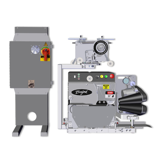
Chapter 1 Unit Overview Ribbon Assembly Tyer Head User Interface Brush Assembly Optional Stand Dancer Arm Ribbon Tension Spring Electrical Hook Up Electrical Panel Main Disconnect Castor... -
Page 17: E-Stop Location
Introduction E-Stop Location Below are the locations for the Emergency Stops (E-Stop) and the Main Disconnect on the unit when on a stand. The E-Stop is located on the user interface panel of the tyer head. The Main Disconnect is located on the Electrical Panel. The operators should become familiar with these locations. - Page 19 Chapter 2 Key Components...
- Page 20 Chapter 2 CHAPTER 2: KEY COMPONENTS Below is a list of key components that you must familiarize yourself with to gain a better understanding of how the Smart Tyer functions. Tyer Head The Tyer Head is made up of all the mechanical and electrical components necessary to perform a closure.
-
Page 21: Chapter 2: Key Components
Key Components Needle The Needle wraps the ribbon around the bag neck and places the ribbon into the Holder / Shear. Needle Cover removed for clarity of component location. -
Page 22: Twister Hook
Chapter 2 Twister Hook The Twister Hook takes the ribbon and twists it to tie the ribbon. Twister Hook Cover removed for clarity of component location. -
Page 23: Holder / Shear
Key Components Holder / Shear The Holder / Shear performs two functions. It shears, or cuts the ribbon for the current closure. It simultaneously holds the ribbon for the next closure. The Holder Shear cycles between the two sides. Each side performs the same function, to shear the ribbon for the current closure and to hold the ribbon for next closure. -
Page 24: Holder / Shear, Cont'd
Chapter 2 Holder / Shear, cont’d. Holding Shearing Surface Edge This part of the This part of the ribbon will be ribbon will be used held for the for the current next closure. closure. -
Page 25: Holder / Shear, Cont'd
Key Components Holder / Shear, cont’d. During the closing sequence the needle will place the ribbon around the bag neck and into the Holder / Shear. The Holder / Shear will cycle, cutting the top of the ribbon to be tied around the current product. -
Page 26: Bag Switch
Chapter 2 Bag Switch The Bag Switch is actuated by the bag neck of the product. When product is being transferred by the conveyor to the gathering belts, the bag neck will force the bag switch to pivot downstream. The bag switch sends a signal to start the closure process. -
Page 27: Package Recognition System
Key Components Package Recognition System The Package Recognition System is an integral part of the Ribbon Tension assembly and the electronics. This system determines whether a bag neck has been properly presented in tying position. As the needle wraps the ribbon around the bag neck, the length of dispensed ribbon is measured. -
Page 28: Ribbon Guide
Chapter 2 Ribbon Guide The Ribbon Guide is positioned so the downstream side of the lobe is flush with the mounting block, with the belt pulley positioned so the upper belt is approximately 1/8” from the needle shaft. It is used to increase or decrease the tie window. -
Page 29: Gathering Belts
Key Components Gathering Belts The Gathering Belts, which move at a selectable continuous rate of speed, transport the bag neck towards the tying position. Belt Speed Switch In normal operation, the Belt Speed switch enables the operator to adjust the speed of the gathering belts. -
Page 30: Operator Panel
Chapter 2 Operator Panel The Operator Panel is located at the top of the tyer head. This is where the operator will control the machine. It houses the E-Stop, Start button, Thread button, Operation Selector Switch, Motors Enabled Light, Initialized Light, Tyer fault light, and the Belt Speed Switch. -
Page 31: Main Enclosure
Key Components Main Enclosure The Main Enclosure contains the necessary components to provide power to the Unit. The Interface for Baggers and / or conveyor interlocks are located in the Main Enclosure. The Main Disconnect is located on the front of the Main Enclosure. -
Page 32: Ribbon Tension Assembly
Chapter 2 Ribbon Tension Assembly The Ribbon Tension Assembly holds the ribbon spools and keeps the ribbon tension tight for a proper tie. It houses the ribbon tension spring, ribbon drop sensor, the ribbon brake, and the dancer arm. The Smart Tyer comes standard with a double ribbon spool holder. -
Page 33: Brake
Key Components Brake The brake should hold firm when the tyer is idle and rotate freely when the tyer is pulling ribbon. It can be adjusted by loosening the set screw at the upper or lower “V” belt clamps. Dancer Arm The Dancer Arm decreases ribbon tension by releasing the brake preassure. -
Page 34: Ribbon Drop Sensor
Chapter 2 Ribbon Drop Sensor The Ribbon Drop Sensor detects if the ribbon is no longer threaded during operations. A ribbon drop can occur for numerous reasons, but it is most common with poor presentation, improper ribbon tension, or debris in the Holder / Shear. -
Page 35: Gathering Brush
Adjustment Knob The Adjustment Knob varies the tension of the gathering brushes. This knob limits the amount of mesh between the upper and lower brushes. Order your replacement brushes from Burford . Call 1-877- ® Burford (1-877-287-3673) Today. Part Number: 210999. -
Page 36: Pressure Regulator
Chapter 2 Pressure Regulator The Pressure Regulator is a valve on the Gathering Brush that automatically cuts off the flow of air at a certain pressure. An adjustable knob is used to control the amount of pressure desired to help flatten the bag tail. Operator Display The Operator Display shows messages sent from the CPU Board program. -
Page 37: Optional Key Components
The following Key Components are items that may be purchased as an upgrade ® with the Burford Smart Tyer. Your unit may or may not have these items on it. ® Contact Burford for further information. Order your Optional Components from Burford . Call 1-877- ® Burford (1-877-287-3673) or email Sales@Burford.com today. -
Page 38: Package Detection Sensor
Package Detection Sensor The Package Detection System monitors packages as they pass through the Burford® Model 2200M/2300M Servo Tyer and stops the bagger or sounds an audible alarm depending on dip switch 6 on Amp board if a twist-tie is not... -
Page 39: Speed Follower Encoder
Key Components Speed Follower Encoder The Speed Follower Encoder gives the tyer the ability to automatically adjust the speed of its gathering belts so that the belt speed changes as the conveyor speed changes. An Encoder is used to monitor a sprocket that rotates with the conveyor. -
Page 40: Stand
Conveyor An optional conveyor is available for your Smart Tyer. The conveyer transfers product through the unit so an closure can be applied. Burford conveyors feature flights that carry the product through the Smart Tyer. Different lengths of conveyors are available. - Page 41 Chapter 3 Installation...
-
Page 43: Chapter 3: Installation Procedures
5/16" bolts and nylon insert nuts provided. Square bracket with conveyor and tighten securely. Mounting Holes These instructions are for a typical bagger. If your specific installation requirements are different from what is described ® here. Contact Burford Corp. at (1-877-287-3673) or Sales@Burford.com for assistance. -
Page 44: Mechanical Installation, Cont'd
Chapter 3 Mechanical Installation, cont’d. Remove the Tyer from the shipping crate and slide the unit onto the Tyer Mounting Bracket. Secure the tyer head using the clamps on the bracket. The centerline of the gathering belts should align with the center of the package. For instance, the belts should be 2 inches above the conveyor for a 4-inch tall package. -
Page 45: Mechanical Installation, Cont'd
Installation Mechanical Installation, cont’d For AMF/UBE bread bagger applications, position the product shelf plate inside the scoop channel. Line up the inlet plate slot with the two (2) studs on the side of the bagger conveyor. Secure with the flat washers and nuts provided. Position the main electrical enclosure within six feet of the Tyer Head. -
Page 46: Mechanical Installation, Cont'd
Chapter 3 Mechanical Installation, cont’d. Locate the four (4) pin power cable connector and thirty (30) pin main control cable connector attached to the main enclosure and connect it to the mating bulkhead connectors on the back of the Tyer. Locate the nineteen (19) pin operator control box connector (if equipped) attached to the main enclosure and connect it to the mating bulkhead connector on the back of the tyer. -
Page 47: Electrical Interconnections
To make specific wiring connections to your bagger or conveyor system please refer to the wiring diagram provided with this manual. The Model 2200M/2300M Electronic Smart Tyer is nominally a 110 VAC machine. If required, minimum service transformer size shall be 1.5KVA. -
Page 48: Counter Output / External Counter Output
Chapter 3 Counter Output / External Counter Output The Smart Tyer comes standard with a relay (CR3), which toggles every time that a valid package is tied. This relay is normally used to drive a customer's external counter, but it can be adapted to serve other functions with external customer logic. -
Page 49: Bagger-Active Circuit
“CYCLING”, 110 VAC is supplied to these wires. Installation Arrangements ® A Burford factory trained Technician may be hired for any installation. The arrangement can be made with the Service Manager Service@Burford.com or: ® Burford Corp. Maysville, Oklahoma ®... -
Page 51: Chapter 4: Operation
Chapter 4 Operation... -
Page 53: Theory Of Operation
When the bag neck releases the bag switch, the Model 2200M/2300M controller waits for a short time before commencing the tie cycle. This delay allows the bag neck to gather against the ribbon for a more secure tie. -
Page 54: Package Recognition System
Chapter 4 Package Recognition System The Package Recognition System is an integral part of the Ribbon Tension assembly and the electronics. This system determines whether a bag neck has been properly presented in tying position. As the needle wraps the ribbon around the bag neck, the length of dispensed ribbon is measured. -
Page 55: Dual Ribbon Spool System
Operation Dual Ribbon Spool System As the ribbon pulls the dancer arm forward, a spring-loaded brake release arm is engaged, causing the ”V” belt to be pushed up and away from the pulley, releasing the brake. The system provides an identical setup, which may be utilized by releasing the locking pin and rotating the assembly 180 degrees. -
Page 56: Package Detection System (Pds)
The Package Detection System monitors packages as they pass the Burford Model 2200M/2300M Servo Tyer and stops the bagger if a twist-tie is not applied. The system automatically resets after the next accepted package. The PDS operates by monitoring the package sensor to determine when a package is in the operating area of the Servo-Tyer. -
Page 57: Speed Following Feature
Operation Speed Following Feature The tyer has the ability to automatically adjust the speed of its gathering belts so that the belt speed changes as the conveyor speed changes. This minimizes the amount of operator input required to operate the tyer. However, it may be necessary for the operator to fine tune the belt speed, as explained later, to achieve the most desirable package. -
Page 58: General Operation
Chapter 4 General Operation The following is a discussion of the overall operation of the Model 2200M/2300M Electronic Smart Tyer. The Smart Tyer is designed so the operator has easy access to controls and adjustments from the front of the machine. The majority of the controls reside on the front of the operator control panel. -
Page 59: Start Up Procedures, Cont'd
Operation Start Up Procedures, cont’d. Next, the operator must push the “START” button on the operator control panel. This will supply power to the servo motors and start the homing sequence. When the homing sequence is successfully completed, the Tyer is in the “RUN” mode. The operator should check the belt speed setting to ensure that it is correct for the current conveyor speed. -
Page 60: Operator Controls
Chapter 4 Operator controls Item Description This button is used to disable the Tyer during operation. The “TYER FAULT” light will turn on and the “MOTORS ENABLED” light will turn off. If the “STOP” button is pushed or the front access cover is “STOP”... -
Page 61: Main Power Disconnect
Operation Main power disconnect The Main Disconnect disconnects the AC power coming to the Tyer controls. This does not disconnect any interlock connections coming from the bagger or conveyor. Audible alarm This Audible Alarm gives the operator audible feedback as to the status of the Tyer. The following is a list of the audible alarm codes. -
Page 62: Changing And Threading The Ribbon
Chapter 4 Changing and threading the ribbon ® The Burford Smart Tyer is equipped with a dual ribbon spool assembly. For clarification on threading, refer to ribbon routing decal next to the ribbon spool on the Tyer. To remove a ribbon spool from the spindle, turn the ribbon chuck in the loosen direction, as marked on the chuck, until the ribbon chuck comes off the spindle. -
Page 63: Changing And Threading The Ribbon, Cont'd
Operation Changing and threading the ribbon, cont’d. Next, guide the ribbon back toward the discharge end and over the bottom roller. Then, slip the ribbon around the back of the access cover handle and thread it down the gap between the two front covers ensuring that the ribbon is captured by the needle. -
Page 65: Chapter 5: Settings And Adjustments
Chapter 5 Settings and Adjustments... -
Page 67: Proximity Sensor Adjustment
Settings and Adjustments CHAPTER 5: SETTINGS AND ADJUSTMENTS Proximity Sensor Adjustment The Smart Tyer has six proximity sensors; four are used to locate the relative position of the needle, holder/shear, twister hook and bag switch. The fifth and sixth sensors are used to measure the amount of ribbon dispensed, and to detect ribbon drop. -
Page 68: Proximity Sensor Locations, Cont'd
Chapter 5 Proximity Sensor Locations, cont’d. The Twister Hood proximity sensor senses the twister hook Twister hook Prox as it rotates. Needle Prox The Needle proximity sensor senses the needle while its in the home postion. Ribbon drop Prox The Ribbon Drop proximity sensor senses the drop tab when the ribbon is not threaded. -
Page 69: Gathering Belts Tension Adjustment
Settings and Adjustments Gathering Belts Tension Adjustment The upper and lower gathering belts are tensioned by moving idler pulleys in slotted holes. Over tightness of the belts places an excess load on the belt motor an may result in a blown fuse on the Amplifier board. -
Page 70: Lower Belt Adjustment
Chapter 5 Lower Belt Adjustment Measure tension of lower gathering belt at area shown. With 2.5 pounds of pressure applied to belt the deflection should be approximately 5/16 of an inch. 5/16” To adjust: re-position lower idler pulley as necessary. -
Page 71: Gathering Brush Tension Adjustment
Settings and Adjustments Gathering Brush Tension Adjustment The tension of the gathering brushes can be varied by using the adjustment knob and tension gauge provided on the top of the brush assembly. This knob limits the amount of mesh between the upper and lower brushes. Record value setting in the chart below. -
Page 72: Gathering Brush Air Adjustments
Chapter 5 Gathering Brush Air Adjustments The gathering brush comes standard with an air regulator. The air blows the bag tail down prior to the gathering brush gathering the bag tail tight against the brush. The amount of air can be adjusted by turning the knob on the regulator to increase or decrease the air flow. -
Page 73: Ribbon Dispenser Adjustment
Settings and Adjustments Ribbon Dispenser Adjustment Release all spring tension from the ribbon assembly by Thumb screw loosening thumb screw and sliding the cantilevered spring stop to relieve spring tension. Set brake tension to 1.5 lbs. by using a pull meter or similar method to measure force pull... -
Page 74: Ribbon Drop Dispenser Adjustment
Chapter 5 Ribbon Drop Dispenser Adjustment Verify the ribbon drop sensor operation. When the ribbon has not been threaded and brake tension is being applied to the dancer arm, the ribbon drop sensor should be sensing the ribbon drop tab. When the ribbon has been threaded and ready for production the ribbon drop sensor should not be sensing the ribbon drop tab. -
Page 75: Spacing Of Twister Hook Shaft To Tip Of Holder / Shear
Settings and Adjustments Spacing Of Twister Hook Shaft To Tip Of Holder / Shear The proper spacing is 3/32”. Holder / Shear must be on the inside position. If these two items are too close, the ribbon will sometimes wrap around the shaft of the hook. If these are too far away, ties will be missed. -
Page 76: Holder / Shear Adjustment
Chapter 5 Holder / Shear Adjustment The force with which each side of the holder/shear holds the ribbon is adjustable to provide the same holding force on each side of the holder/shear. Verify electrical power has been removed from the tyer head. Remove large back cover from rear of tyer head. -
Page 77: Holder/Shear Adjustment, Cont'd
Settings and Adjustments Holder/Shear Adjustment, Cont’d. Remove tunnel plate. Locate holder/shear cam. Rotate holder/shear cam a few times to obtain a “feel” for its operation. Rotate holder/shear cam until the point where it begins to resist further rotation. Measure this distance to an arbitrary point. Rotate the holder/shear cam 180 degrees and measure again to the same arbitrary point. -
Page 78: Holder/Shear Adjustment, Cont'd
Chapter 5 Holder/Shear Adjustment, Cont’d. If not equal distances, then loosen shuttle bar bolts. Now when the cam is rotated the holder/shear mounting plate will slide in either direction along the shuttle bar. Rotate holder/shear cam and measure until distances are equal. This will require tightening and loosening the shuttle bar bolts after each attempt. -
Page 79: Adjusting The Tie Tightness
Settings and Adjustments Adjusting The Tie Tightness There are two adjustments on the Model 2200M and 2300M Tyers to adjust the tie tightness. One adjustment is the ribbon guide position and the other is the upper belt pulley position. To correctly adjust these it is important to understand how this area of the Tyer works. -
Page 80: Factory Setting
Chapter 5 Factory Setting The ribbon guide is positioned so the downstream side of the lobe is flush with the mounting block, with the belt pulley positioned upper belt approximately 1/8” from the needle shaft. Adjusting The Ribbon Guide The ribbon guide adjustment is for fine tuning the tie window area and can be adjusted by opening the front cover, loosening the ribbon guide, and sliding the... -
Page 81: Adjusting The Belt Pulley
Settings and Adjustments Adjusting the belt pulley If after adjusting the ribbon guide the bag is still not tied with the proper tension, the upper belt pulley may need to be adjusted. First, loosen the mounting bolt and nut of the upper belt pulley. -
Page 82: Dip Switch Settings On Amplifier Board
Package Recognition cycle abort inactive active Normal tie cycle speed Maximum tie cycle speed Four twists by twister hook. Five twists by twister hook. H1 Jumper Settings LH position RH Position For Model 2300M belt motor direction. For Model 2200M belt motor direction. -
Page 83: Dip Switch Settings On Cpu Board
Settings and Adjustments DIP Switch Settings on CPU board The CPU board, P/N C01410, has a group of eight DIP switches labeled S1. The following table identifies the switch functions. Switch # OFF Position ON Position Not Used. Not Used. Not Used. - Page 85 Chapter 6 Communications...
-
Page 87: Chapter 6: Communications
® The Burford Model 2200M/2300M Twist Tyer has the ability to communicate with a terminal or a personal computer which is running a terminal emulation program. When the tyer's controller detects an unusual situation or an error, the controller sends diagnostic information to the terminal through its serial port. -
Page 88: Burford ® Terminal Program
Burford Corp. has developed a terminal emulation program specifically for use with the Model 2200M/2300M tyers. This program is simply called TERMINAL.EXE and it provides the simplest and easiest way of communicating with the tyer's controller and capturing data to files. The program is already configured for 4800 Baud, Even Parity, 8 Data Bits and 1 Stop Bit. -
Page 89: Terminal Program In Microsoft Windows Version 3.0 Or 3.1
® Terminal program, which can be used to communicate with the Burford Model ® 2200M/2300M tyer. This terminal program is not as easy to use with the Burford tyer as ® Burford Terminal program described above and it requires some time to configure the program. -
Page 90: Configuring The Microsoft Windows Terminal Program, Cont'd
The tyer's controller sends some information to the serial port which is intended to be ® ® displayed on the optional Operator Display provided by Burford Corp. The Burford TERMINAL program has been written to recognize the format of these statements and display them in a box near the bottom of the screen. -
Page 91: Safety Considerations
Communications Safety considerations When working with the tyer, the following points should be observed: This activity should only be conducted by qualified personnel. When troubleshooting a problem, it may be necessary to have the main electrical enclosure open in order to view the status lights or to make voltage checks while the machine is operating. -
Page 92: Tyer Commands
Not all of the possible tyer commands will be discussed in this document. Many of these ® are too technical to be helpful to anyone other than Burford Service Personnel. When you start the tyer When power is first supplied to the tyer’s controller, it automatically sends out several lines of information, which look similar to the following. -
Page 93: When You Start The Tyer, Cont'd
Communications When you start the tyer, cont’d. At this point, the controller is waiting for you to push the RUN button on the small operator's control box and you are prevented from typing in commands. After the run button is pressed, the tyer begins to perform its homing sequence for 3 of the motors. (The fourth servomotor drives the bag gathering belts and it does not have a home position.) While the tyer is homing, several lines of information are written to the screen about the progress of the homing sequence. -
Page 94: Time And Date Commands
Chapter 6 TIME and DATE commands The tyer's controller has a battery-powered real-time clock that it uses to record the time and date of special events. It is good practice to check the time and date before going on to other activities. If the time and date are not accurate, then the time and date information recorded will be incorrect. -
Page 95: Trouble Command
Communications TROUBLE command The tyer's controller keeps a record of important events and problems that it encounters during operation. This record is stored in battery-backed memory on the CPU board. This record provides a valuable history of operation for this machine, which can be very helpful in diagnosing problems. -
Page 96: Query Command
Therefore, the most likely customer use for this command is to display data, which can be captured into a text file see pg. 84 for information on capturing files. Then the customer ® would normally print the file and fax the data to Burford Corp. for analysis Contact the Service Manager at Service@Burford.com... -
Page 97: Query Command, Cont'd
Communications QUERY command, cont’d. MOTOR 1>q=0 MOTOR 1>q Step Time Set VEL CMD 0> 0.0 -2.1 -2132.9 1> 5.2 504.8 2> 10.5 7122.3 3> 15.7 13.6 13560.3 4> 21.0 21.4 21418 5> 26.2 28.2 28246.5 6> 31.5 34.1 34093.7 7> 36.7 35.9 35859.8 8>... -
Page 98: Reset Command
Chapter 6 RESET command This command causes the tyer's controller to display the reason for the most recent controller reset. It does not cause the tyer's controller to reset itself. The possible reasons for a reset are: Power turned off. This is the most common cause of a reset and it is quite normal for this to occur. -
Page 99: Home Command
Communications HOME command When the screen is displaying a prompt such as MOT>1, typing HOME causes the tyer to begin a homing sequence. This can also be accomplished by holding the thread button on the Operator's Control Box for 5 seconds. DISPENSE command Every time that the tyer is triggered, the tyer's controller counts the number of pulses that it receives from the Bag Recognition System proximity switch. -
Page 100: Dispense Command, Cont'd
Chapter 6 DISPENSE command, cont’d. The exact format of the output depends upon which PROM Version you have. The output to the screen will look approximately like this. PASSED: RIBBON DISPENSER TIE COUNT at checkpoint was 19 > 17 -3. PASSED: RIBBON DISPENSER HEEL COUNT at checkpoint was 20 <... -
Page 101: Command
Communications + command This command provides a "back door" way of getting access to the tyer's controller if the tyer will not successfully home or if you wish not to home the tyer. This command causes the tyer to bypass the homing sequence that normally must successfully complete before you can type commands. -
Page 102: Capturing Data Into A Text File On The Pc
Chapter 6 Capturing data into a text file on the PC ® With the Burford TERMINAL program To begin capturing data, press Alt-F. A unique filename, based on the time and date, will be suggested in the dialog box in the center of the screen. You may use this filename or type in any other name permitted by DOS. - Page 103 Chapter 7 Troubleshooting...
-
Page 105: Chapter 7: Troubleshooting
Troubleshooting CHAPTER 7: TROUBLESHOOTING Diagnostic LED's The specifications defined below apply to Amplifier Board P/N 611484. The Amplifier Board has forty-six LED's to assist in troubleshooting the Tyer. D50, D51 NEEDLE Phase A and NEEDLE Phase B Indicates input signals from the needle motor encoder. Each LED should blink on and off as the needle is moved back and forth. -
Page 106: Diagnostic Led's, Cont'd
Chapter 7 Diagnostic LED's, cont'd. D83 RIBBON DISP Indicates when one of the steel dowels in the ribbon dispenser spool is covering the ribbon dispense proximity sensor. D62 BAG SWITCH Indicates when the bag switch is depressed. D78 H/S HOME Indicates when the holder shear home proximity sensor is covered by the tabs on the holder shear shuttle cam. -
Page 107: Diagnostic Led's, Cont'd
Troubleshooting Diagnostic LED's, cont'd. D3 SERVO ENABLED RELAY Indicates when the servos enabled relay, CR2 on the Amplifier Board, is energized. D57, D58, CPU0, CPU1 Indicates CPU activity. D68 HORN Indicates power is being sent to the horn. D55, D56, PCS0, PCS1 Indicates CPU activity. -
Page 108: Seven Segment Led Error Codes
Chapter 7 Seven Segment LED Error Codes Mounted on the operator panel is the seven segment LED which can display all of the numbers and most of the alphabet, one character at a time. This device is used to display various codes that give the Tyer's status and may be helpful in troubleshooting. -
Page 109: Seven Segment Led Error Codes, Cont'd
Troubleshooting Seven Segment LED Error Codes, cont’d. CODE DESCRIPTION E112 Trailing edge of needle prox not found E113 Leading edge of needle prox not found E114 Can't move needle to home position E115 Needle motor not moving E116 Needle jammed or encoder fault E117 Needle home prox. -
Page 110: Audible Alarm Codes
Chapter 7 Audible Alarm Codes A long beep is 1 second in duration. A short beep is 1/2 second in duration. Alarm Display Code Description 1 Short None Power turned on, or home sequence successful. Bag necks too close together (tried to start 2 cycle 2 Short H006... - Page 111 Troubleshooting TYER WILL NOT POWER UP No Error Code is Displayed SAFETY WARNING The following troubleshooting procedure may require that tests be made with the electrical enclosures open and power turned ON. These tests should only be conducted by authorized personnel who are aware of the electrical and mechanical hazards present.
- Page 112 Chapter 7 Tyer Will Not Power Up, cont'd. No Error Code is Displayed SAFETY WARNING The following troubleshooting procedure may require that tests be made with the electrical enclosures open and power turned ON. These tests should only be conducted by authorized personnel who are aware of the electrical and mechanical hazards present.
- Page 113 Troubleshooting GATHERING BELTS WON'T RUN No Error Code Is Displayed SAFETY WARNING The following troubleshooting procedure may require that tests be made with the electrical enclosures open and power turned ON. These tests should only be conducted by authorized personnel who are aware of the electrical and mechanical hazards present.
- Page 114 Chapter 7 MOTOR FOR GATHERING BRUSHES WON'T No Error Code is Displayed SAFETY WARNING The following troubleshooting procedure may require that tests be made with the electrical enclosures open and power turned ON. These tests should only be conducted by authorized personnel who are aware of the electrical and mechanical hazards present.
- Page 115 Troubleshooting TYER WON'T ALLOW BAGGER TO START No Error Code is Displayed SAFETY WARNING The following troubleshooting procedure may require that tests be made with the electrical enclosures open and power turned ON. These tests should only be conducted by authorized personnel who are aware of the electrical and mechanical hazards present.
- Page 116 Chapter 7 Error Code: E001 Tie cycle aborted because the ribbon is not threaded. This error occurs when the tyer is triggered and the Ribbon Dropped Prox input is ON. SAFETY WARNING The following troubleshooting procedure may require that tests be made with the electrical enclosures open and power turned ON.
- Page 117 Turn off the power on the main electric box to reset the microprocessor. Wait 5 seconds. Turn on power and check for normal operation. If the problem persists, replace the CPU board and notify Burford ® Corp. of this problem.
- Page 118 Chapter 7 Error Code: E102 HOMING sequence failed. This error only occurs while the tyer is in its homing sequence. It indicates the homing sequence took too long. One or more of the Servo Motors were unable to complete their HOMING sequence. SAFETY WARNING The following troubleshooting procedure may require that tests be...
- Page 119 Troubleshooting Error Code: E111 Unable to control needle while homing. This error only occurs while the tyer is in its homing sequence. It indicates either of two similar conditions. E112 indicates that the controller detected the needle's home prox turning ON, but it cannot drive the needle past the prox to turn the prox OFF.
- Page 120 Chapter 7 Error Code: E112 or E113 Only one edge of needle's home prox is detected. This error only occurs while the tyer is in its homing sequence. It indicates either of two similar conditions. E112 indicates that the controller detected the needle's home prox turning ON, but it cannot drive the needle past the prox to turn the prox OFF.
- Page 121 Troubleshooting Error Code: E114 Controller is not able to move the needle to its starting position. This error only occurs while the tyer is in its homing sequence. After all motors have found their home proxes, the controller tries to move all motors to their starting positions.
- Page 122 Chapter 7 Flow Chart 0-12 Error Code: E115 and E116...
- Page 123 Troubleshooting Flow Chart 0-13 Error Code: E115 and E116, cont'd.
- Page 124 Chapter 7 Flow Chart 0-14 Error Code: E117...
- Page 125 Troubleshooting Error Code: E121 Unable to control hook while homing. This error only occurs while the tyer is in its homing sequence. It indicates either of two similar conditions. E122 indicates that the controller detected the hook’s home prox turning ON, but it cannot drive the hook past the prox to turn the prox OFF.
- Page 126 Chapter 7 Flow Chart 0-16 Error Code: E122 or E123...
- Page 127 Troubleshooting Flow Chart 0-17 Error Code: E124...
- Page 128 Chapter 7 Flow Chart 0-18 Error Code: E125 and E126...
- Page 129 Troubleshooting Flow Chart 0-19 Error Code: E125 and E126, cont'd.
- Page 130 Chapter 7 Flow Chart 0-20 Error Code: E127...
- Page 131 Troubleshooting Flow Chart 0-21 Error Code: E131...
- Page 132 Chapter 7 Flow Chart 0-22 Error Code: E132 or E133...
- Page 133 Troubleshooting Flow Chart 0-23 Error Code: E134...
- Page 134 Chapter 7 Flow Chart 0-24 Error Code: E135 and E136...
- Page 135 Troubleshooting Flow Chart 0-25 Error Code: E135 and E136, cont'd.
- Page 136 Chapter 7 Flow Chart 0-26 Error Code: E137...
- Page 137 Troubleshooting Error Code: E146 Belt Motor Fuse Blown, Motor Stalled, or Bad Encoder These error codes are set when the controller is trying to move the belt motor, but the motor either isn't moving or the controller cannot tell that the motor is moving.. SAFETY WARNING The following troubleshooting procedure may require that tests be made with the electrical enclosures open and power turned ON.
- Page 138 Chapter 7 Flow Chart 0-28 Error Code: E146, cont'd.
- Page 139 Wait 5 seconds. Turn on power and check for normal operation. If the problem persists, replace the CPU board and notify Burford Corp. of this problem. Flow Chart 0-29 Error Code: E151 through E169...
- Page 140 Turn off the power on the main electric box to reset the microprocessor. Wait 5 seconds. Turn on power and check for normal operation. If the problem persists, replace the CPU board and notify Burford Corp. of this problem. Flow Chart 0-30 Error Code: E300...
-
Page 141: Mechanical Troubleshooting
Troubleshooting Mechanical Troubleshooting Problem Description Probable Cause Recommended Action 1a. Check that ribbon dispenser is working freely. 1b. Check that ribbon on spool is not wrapped over itself, 1. Excessive ribbon tension. preventing ribbon from unspooling correctly. 1c. Reduce ribbon tension by moving end of tension spring on adjustment rod. -
Page 142: Mechanical Troubleshooting, Cont'd
Chapter 7 Mechanical troubleshooting, cont’d. Problem Probable Cause Recommended Action Description 1. Excessive ribbon tension. 1. See pg.71 for proper tension adjustment. 2. Poor quality ribbon. 2. Replace ribbon. Twist tie ribbon breaks 3. Bag tail presentation from the exit of the bagger must be during tying operation. -
Page 143: Mechanical Troubleshooting, Cont'd
Troubleshooting Mechanical troubleshooting, cont’d. Problem Probable Cause Recommended Action Description 1. Too much ribbon tension. 1. See pg. 71. 2. Too many twists. 2. See pg. 71. 3. Upper & lower covers 3. Clean upper & lower covers with emery cloth to remove have a. - Page 145 Chapter 8 Maintenance...
-
Page 147: Chapter 8: Maintenance
Preventive Maintenance ® Burford Corp. recommends the following preventive maintenance schedule to insure ® proper performance of your Burford Electronic Smart Tyer. Lubrication The two-flanged bearings supporting the needle shaft should be lubricated twice a year. -
Page 148: Daily
Chapter 8 Daily Clear bags from brush assembly. Weekly Check to ensure cable connectors, located on the back of the tyer head, are tight. Ensure all ribbon rollers turn freely and the dancer arm releases ribbon in the proper position. Ensure all switches and lights function properly. - Page 149 Maintenance Semi-Annual Grease all bearings. Check DIP switches for proper settings. Check bag stop. Check brake arms and cam followers on dancer arms. Check the lower belt guide (check belt guide supports to move freely). Check the Holder/Shear (See pg. 74). Annual Check the shuttle bar bearing block.
- Page 150 Chapter 8 Pass Thru Shelf on Dual Tyer Setup When operating with a dual tyer setup and a fault occurs during production and a tyer needs to be bypassed, the following procedure should be followed. Moving machinery may cause serious injuries and damage.
- Page 151 Maintenance Pass Thru Shelf, cont’d. Moving machinery may cause serious injuries and damage. Keep all objects and personnel away from moving machinery. 4. Remove bypass shelf from tyer currently being bypassed by lifting “UP” on bypass shelf using the slots on top of shelf. 5.
- Page 152 Chapter 8 PROM Replacement Procedure ® The computer program for the Burford Model 2200M/2300M Electronic Smart Tyer resides in two PROMs, U6 and U9 on the CPU board. Each PROM contains half of the program. To upgrade the Smart Tyer to the latest program, the PROMs must be replaced with a new version.
- Page 153 Maintenance PROM Replacement Procedure, cont'd. Slowly push the screwdriver under the PROM while twisting the blade. Work your way towards the back of the PROM. Do not pry the front of the PROM up too quickly or you will bend the pins in the back. Carefully remove the PROM straight up from the socket being careful not to bend any pins.
- Page 155 Chapter 9 Test Procedures...
- Page 157 Test Procedures CHAPTER 9: TEST PROCEDURES Test procedure for motor encoders The following test procedures may require that tests are made with the electrical enclosures open and power turned “ON”. These tests should only be conducted by authorized personnel who are aware of the electrical and mechanical hazards present.
- Page 158 Chapter 9 Test procedure for motor continuity The following test procedures may require that tests are made with the electrical enclosures open and power turned “ON”. These tests should only be conducted by authorized personnel who are aware of the electrical and mechanical hazards present.
- Page 159 Test Procedures Test procedure for servo motor fuses The following test procedures may require that tests are made with the electrical enclosures open and power turned “ON”. These tests should only be conducted by authorized personnel who are aware of the electrical and mechanical hazards present.
- Page 160 Chapter 9 Test procedure for checking the proximity switch LED’s The following test procedures may require that tests are made with the electrical enclosures open and power turned “ON”. These tests should only be conducted by authorized personnel who are aware of the electrical and mechanical hazards present.
- Page 161 Test Procedures Test procedure for the BCD switch The following test procedures may require that tests are made with the electrical enclosures open and power turned “ON”. These tests should only be conducted by authorized personnel who are aware of the electrical and mechanical hazards present.
- Page 162 Chapter 9 Test procedure for the bag switch The following test procedures may require that tests are made with the electrical enclosures open and power turned “ON”. These tests should only be conducted by authorized personnel who are aware of the electrical and mechanical hazards present.
- Page 163 Incompatible enclosure/tyer head combinations without the jumper, result in error code H004. Open the main electrical enclosure. Locate terminal strip (TB1). ® If wire P1:34 is present, then jumper (Burford P/N C06369) must be inserted to connect wires P1:33 and P1:34.
- Page 165 Chapter 10 Parts and Drawings...
- Page 167 ® In order to prevent valuable down time, Burford Corp. recommends the following parts be kept in stock. ® Please have the following machine information on hand before calling Burford • Machine Voltage • Model Number • Serial Number 2200M...
- Page 168 Chapter 9 RECOMMENDED SPARE PARTS LIST, cont’d 2200M 2300M Description Qty. Gearbelt, 925MM X 9MM, 5HTD (Front 611456 611456 Bottom - Red) 611464 611464 Board, Amplifier 611514 611514 Spring Extension, .380D X .026WD X 1.5FL 611929 611929 Belt, Single, 9MM Wide X 5MM HTD, 100T...
- Page 169 See Chapter 9 for specific details on this display. The CPU board is considered a replacement unit. The proprietary software used to control the Smart Tyer ® was developed by Burford Corp. and cannot be altered in the field. Amplifier board part number 611464 The AMP Board is a ten and one half inch by eleven inch circuit board that is controlled by the CPU Board through the seventy-two pin connector J1.
- Page 170 Chapter 9 Relay Descriptions Panel relays main enclosure SR1, (611508) Latches in logic power (J4 connector on Amplifier board). CR0 (611455) Connects 48VDC motor power to Amplifier board (T1 connector). CR1 (610374) Latches the bagger clutch signal. CR2 (610404) Latches the bagger enable signal. CR3 (610404) External counter contacts.
- Page 171 Contents Frame Assembly Shaft Bearing Assembly Front Lower Plate Front Upper Plate Drive Components Electrical Components Infeed Belt Components Board Mount / Connector Plate Ribbon Assembly Ribbon Tension Assembly Ribbon Frame Assembly Tapered Brush Assembly Tapered Brush Detail Assembly Tapered Brush Air Regulator Stand Assembly Pass Thru Kit Brush Bun Kit / Dual Brush Kit...
- Page 172 Drawings & 2200M Frame Assembly 211102-01 RH Rev A 211101-01 LH Rev A Parts QTY. ITEM # PART# DESCRIPTION 174248 MOUNT, CABLE 302021 BUSHING, MACH, ¼ X ½ X .010 302279 ASSY, SHUTTLE BLOCK 611306 HINGE, LIFT OFF (ZINC) 714000 PLATE, FRONT MAIN, SERVO...
- Page 173 Right Hand Shown...
-
Page 174: Frame Assembly
Frame Assembly 2200M Drawing 211102-01 Rev A Shaft Bearing Assembly 211102-02 Rev A RH 211101-02 Rev A LH QTY. ITEM # PART# DESCRIPTION 210724 ASSY, NEEDLE, 2200,LOW (RIGHT HAND) 210723 ASSY, NEEDLE, 2300,LOW (LEFT HAND) 611238 BEARING, 5/8, 2 BOLT FLANGE, SST... - Page 175 Frame Assembly 2200M Needle Assembly 2200 Low Drawing 211102-02 Rev A Right Hand Shown 986912 SCREW BUTT HD SOC #8-32 X 3/4 SST 986908 SCREW BUTT HD SOC #8-32 X 1/2 SST 978316 SCREW SOC HD CAP 1/4-20 X 1 SST...
-
Page 176: Front Lower Plate
Shaft Bearing Assembly 2200M Front Lower Plate Assembly Drawing 211102-02 Rev A 211102-03 RH Rev A 211101-03 LH Rev A QTY. ITEM # PART# DESCRIPTION 210607 ASSY., MAIN IDLER 210609 ASSY, BACKSIDE IDLER 210722 ASSY, TWISTER HOOK, 2200, LOW (RIGHT HAND) - Page 177 FRONT LOWER PLATE ASSEMBLY 211102-03 REV A Shuttle Bar Assembly 211037 Rev A QTY. ITEM # PART# DESCRIPTION 211036 ASSY, LOWER GUIDE ARM 715788 SHUTTLE BAR 715792 GUIDE, LOWER BELT (RIGHT HAND) 302146 OIL FILLED BUSHING 715793 GUIDE, LOWER BELT (LEFT HAND) QTY.
- Page 178 715778 BLOCK, UPPER BELT GUIDE Lower Guide Arm, (211036) Arm, Arm, 716214 A/W, LOWER GUARD FLUSH, 2200M 716213 A/W, LOWER GUARD FLUSH, 2300M 716234 BLOCK, SPACER DOOR STOP 2200M 716235 BLOCK, SPACER DOOR STOP 2300M 955621 NUT HEX NYLOC #10-24 UNC SST...
- Page 179 Front Upper Plate 2200M (211102-04 REV D) Right Hand Shown...
-
Page 180: Front Upper Plate
611452 BELT, TWISTER HOOK 611453 BELT, REAR DRIVE 611454 BELT, TWISTER HOOK 714004 SPACER, .5 OD X .266ID X .195 L 714007 BRACKET, HOL-SHEAR SHUTTLE, 2200M 714126 BRACKET, HOL-SHEAR SHUTTLE, 2300M 714011 STANDOFF, PIVOT PLATE 714034 NUT, PULLEY ADJUSTMENT 955619 NUT HEX NYLOC 5/16-18 UNC SST 955940 WASHER LOCK 1/4”... - Page 181 611458 ENCODER, NEW SERVO 611457 MOTOR,BRUSHLESS,48VDC,W/HALLS QTY. ITEM # PART# DESCRIPTION A02390 BUSH, MACH, 1/4 ID X 1/2 OD X .018 989932 SCREW FIN HEX 1/4-20 X 2 SST 978316 SCREW SOC HD CAP 1/4-20 X 1 SST 978308 SCREW SOC HD CAP 1/4-20 X 1/2 SST 955661 NUT HEX NYLOC 1/4-20 UNC SST 714079 BUSHING, SHUTTLE LINK 714078 ARM, HUB H/S INDICATOR...
-
Page 182: Drive Components
Electrical Components Assembly Drive Components 2200M 211102-06 Rev C Drawing 211102-05 Rev A 211101-06 Rev C QTY. ITEM # PART# DESCRIPTION QTY. ITEM # PART# DESCRIPTION 112643 SERIAL PLATE 955941 WASHER LOCK #10 SST 122222 BUSHING 1/2X3/4X.074 MACH 955942 WASHER LOCK #8 SST... - Page 183 See Pg. 16 See Pg. 16 Electrical Components 2200M (211102-06 REV C) Right Hand Shown...
-
Page 184: Electrical Components
Electrical Components 2200M Infeed Belt Components Drawing 211102-06 Rev C 211106 Rev B RH 211105 Rev B LH QTY. ITEM # PART# DESCRIPTION 152193 SPRING EXTENSION 210607 ASSY., MAIN IDLER 210608 ASSY., IDLER ARM 210624 ASSY., BUSHING BLOCK, BRUSH MNT. - Page 185 Infeed Belt Components 211106 Rev B Right Hand Shown...
- Page 186 Infeed Belt Components 2200M Board Mount Asssembly 2200M 210616 Rev B RH Drawing 211106 Rev B 210615 Rev B LH QTY. ITEM # PART# DESCRIPTION 174069 STANDOFF,#6-32 X 1/2,ALUM,HEX 174819 STANDOFF,#6-32 X 3/4,ALUM,HEX 175081-001 CABLE ASSY, DIP TYPE, TTP2 (NEW) REF.
- Page 187 Board Mount Assembly 210616 Rev B RH Connector Plate 210625 Rev B Right Hand Shown * Not Shown...
-
Page 188: Board Mount / Connector Plate
Ribbon Assembly Board Mount Assembly 210626-002 Rev “5” Drawing 210615 Rev B RH Drawing 210616 Rev B LH Connector Plate 210629-001 ASSY, SINGLE RIBBON TENSION Drawing 210625 Rev B 210629-002 ASSY, SINGLE RIBBON TENSION 210635 ASSY, RIBBON HUB/BUSHING 611550 PLUNGER,DETENT SST 1/2-13, L-HANDLE 711757 COLLAR, SET, 1”... - Page 190 Ribbon Tension Assembly Ribbon Assembly 2200M 210629-001 Rev “5” 210629-002 Rev “5” Drawing 210626-002 Rev “5” -002 -001 ITEM # PART# DESCRIPTION 103519 SPRING EXTENSION 104239 CLAMP RIBBON FEED BELT 122221 BUSHING, 1/2 X 3/4 X .036 MACH. 122222 BUSHING, 1/2 X 3/4 X .074 MACH.
-
Page 192: Ribbon Tension Assembly
Ribbon Tension Assembly Drawing 210629 Rev “5” Ribbon Assembly Frame 211104 Rev A 211103 Rev A QTY. ITEM # PART# DESCRIPTION REF. 210624 ASSY., BUSHING BLOCK, BRUSH MNT. 210626-002 ASSY, PIVOTING DUAL RIBBON 2200 RH 210626-001 ASSY, PIVOTING DUAL RIBBON 2300 LH 610884 TY-RAP, MOUNTING HANGER 611477... - Page 193 Right Hand Shown...
-
Page 194: Ribbon Frame Assembly
Ribbon Frame Assembly Tapered Brush Assembly 210999-002 Rev D RH Drawing 211104 Rev A 210999-001 Rev D LH QTY. ITEM # PART# DESCRIPTION 111177 DECAL,110/115/120 VOLTS,1 PHASE 210999-008 ASSY,TAPERED BRUSH RH 210999-007 ASSY,TAPERED BRUSH LH 2.3” 610360 TERMINAL, DIN RAIL, MINI 610361 TERMINAL, BLOCK, MINI 610362... - Page 195 Right Hand Shown...
-
Page 196: Tapered Brush Assembly
Tapered Brush Assembly Detail Tapered Brush Assembly RH 210999-008 Rev F Drawing 210999-002 Rev D QTY. ITEM# PART# DESCRIPTION QTY. ITEM # PART# DESCRIPTION 611931 DIAL INDICATOR, 2-3/8 FACE, .25” 715733 BUSH,MACH 611932 COVER, TAPERED BRUSH ARM 955938 WASHER, LOCK 3/8” SST 611933 COVER, TAPERED BRUSH BACK 955939... - Page 197 Brush Shaft LH 715731 HUB, TAPERED BRUSH MNT, 20MM 715729 SHAFT, 20MM BRUSH, LH 611935 BEARING, 20MM ID X 37MM OD X 9MM QTY. ITEM # PART # Revision DESCRIPTION Brush Shaft LH Brush Shaft RH 715731 HUB, TAPERED BRUSH MNT, 20MM 715730 SHAFT, 20 MM BRUSH, RH 611935...
-
Page 198: Tapered Brush Detail Assembly
Tapered Brush Air Regulator Tapered Brush Assembly Detail Drawing 211173 Rev A Drawing 210999-008 Rev F QTY. ITEM # PART# DESCRIPTION 112201 VALVE, AIR REGULATOR, 1/4NPT 118517 WIRE HOLDER LOCK SST 118873 GAUGE,0-60 PSI,1/4 NPT,BACK MT,BRS 401152 FITTING,CONN,1/4MPT X 1/4T,EN- P,Q.R. - Page 199 Tapered Brush Air Regulator Drawing 211173 Rev A...
- Page 200 Tapered Brush Air Regulator Optional Stand 210633-XXX Rev 2 Drawing 211173 Rev A -001 -002 -003 ITEM # PART# DESCRIPTION 101127 SPROCKET, 41-B-15 1/2 BORE 101136 SPACER, .75 OD x .38 ID x .50 L 152102 BUSH,BRZ,1/2 ID X 5/8 OD X 1/2LG 152106 COLLAR,1/2”...
-
Page 202: Pass Thru Kit
Pass Thru Kit Smart Servo Stand 210998-XXX Rev 5 Drawing 210663-XXX Rev 2 ITEM # PART# DESCRIPTION 302347 A/W, LEG SUPPORT 302360 A/W, STAND, ELEC. ENCLOSURE 302389 LEG, BASE 302458 CONDUIT ASS’Y 8 FT AMF M50 713667 ANGLE, EQUIPMENT BOX MOUNT 713985 A/W, TRANSFER SHELF DBL 713999 BRACKET SUPPORT EXT BRUSH REF. - Page 204 Pass Thru Kit Dual Drawing 210998-XXX Rev 5 Taper Brush Bun Kit 211032 Rev C RH 211033 Rev C LH QTY. ITEM # PART# DESCRIPTION 715769 A/W, 2200/2300 TAPERED BRUSH MNT 955409 NUT JAM 1/4-20 UNC 955938 WASHER, LOCK 3/8” SST 988920 SCREW FIN HEX 3/8-16 X 1 1/4 SST 989908 SCREW FIN HEX 1/4-20 X 1/2 SST A05020 COLLAR,3/4”...
- Page 206 Operator Display Smart Servo Tapered Brush Kits 210186 Rev J Drawing 211032 Rev C Drawing 211026 Rev C QTY. ITEM # PART# DESCRIPTION 174069 STANDOFF,#6-32 X 1/2,ALUM,HEX 210203 ASSY,CABLE,COMM,ERROR DISP-2200 210204 ASSY,CABLE,PWR,DISPLAY-POWER SUPPLY 302450 WASHER, DISPLAY PIVOT 610000 DISPLAY, VFD (PRODUCTION) 610001 DISPLAY, FILTER (GREEN) 610004 STANDOFF, #4-40 UNC, .625 L.
-
Page 208: Operator Display
Operator Display Install Kit Drawing 210186 Rev J Drawing 103531-200 ITEM # PART# DESCRIPTION 103531-100 PLATE, PRODUCT GUIDE TEC200R/2200 103531-101 PRODUCT SHELF, 2200 103531-102 TEMPLATE,STYER-SEALER,MARK 75 110129 SPACER, .38 ID x .75 OD x .25 L SS 302347 A/W, LEG SUPPORT 302360 A/W, STAND, ELEC. - Page 209 Install Kit Drawing 103531-200...
- Page 210 Install Kit Drawing 103531-200 Electrical Schematics FOLD OUT TO VIEW DRAWING...
- Page 211 EDO651 J ladder...
- Page 212 EDO651 J EDO651 J ladder Wire Diagram FOLD OUT TO VIEW DRAWING...
- Page 214 EDO651 J EDO651 J Layout Wire Diagram FOLD OUT TO VIEW DRAWING...
Need help?
Do you have a question about the 2200M and is the answer not in the manual?
Questions and answers
I was wondering if you could provide different type of belts for the gathering belts on a 2200M, i feel the ones it comes with originally don't work as good with the material I'm working with. I feel it needs better grip to pull the bag I'm working with, the plastic is a thick film used on chip products. Do you provide a different type of belt?