
Related Manuals for mercor mcr-PROLIGHT DVP


Summary of Contents for mercor mcr-PROLIGHT DVP
- Page 1 ul. Grzegorza z Sanoka 2 80 – 408 Gdańsk tel. +48 58 341 42 45 tel./fax +48 58 341 39 85 OPERATION AND MAINTENANCE MANUAL mcr-PROLIGHT spot smoke vents type DVP, DVPS type DVP type DVPS Gdańsk ver. 2.2.6 - 2017.09.12...
-
Page 2: Table Of Contents
mcr-PROLIGHT : DVP, DVPS VENTS TYPE PERATION AND MAINTENANCE MANUAL TABLE OF CONTENTS 1. INTRODUCTION ..................... 3 2. PURPOSE OF DEVICE ..................3 3. DEVICE DESIGN AND PRINCIPLE OF OPERATION ..........3 4. TRANSPORT AND DELIVERY ................5 5. DEVICE INSTALLATION ..................6 5.1. -
Page 3: Introduction
• elongating evacuation routes mcr-PROLIGHT smoke vents are part of a smoke control system that comprises other MERCOR SA products, including, among others: mcr-PROLIGHT smoke vents in continuous skylights and single skylights, mcr-PROSMOKE smoke curtains, mcr 9705 and mcr 0204 control units, and others. - Page 4 mcr-PROLIGHT : DVP, DVPS VENTS TYPE PERATION AND MAINTENANCE MANUAL • multi-chamber polycarbonate of thickness from 10 to 25 mm, with different opacities and different heat transfer coefficients, • ALU laminate layers (aluminum - thermal insulation - aluminium. mcr-PROLIGHT type DVP, DVPS vents are offered with the following control systems: •...
-
Page 5: Transport And Delivery
mcr-PROLIGHT : DVP, DVPS VENTS TYPE PERATION AND MAINTENANCE MANUAL b) ALU laminated panel a) polycarbonate panel Fig. 2 Typical glazing of mcr-PROLIGHT type DVP smoke vents 4. TRANSPORT AND DELIVERY mcr-PROLIGHT type DVP, DVPS vents are delivered pre-assembled, but in specific cases (additional external processing, low base heights, etc.) they may be delivered in the form of assemblies. -
Page 6: Device Installation
Ø6 mm wood Fig. 4 Method of mcr-PROLIGHT DVP positioning on the roof - fixtures spacing The vent bases are ready for flashing works with roofing paper, PVC membrane or steel sheet. The vent base, in its upper part, features a galvanized steel sheet strip at its full circumference, which is used for fixing flashings/coverings using screws. -
Page 7: Methods Of Vents Placement
mcr-PROLIGHT : DVP, DVPS VENTS TYPE PERATION AND MAINTENANCE MANUAL 2. After installing the vent, protective foil must be removed from all external aluminium elements of the vent (pressing frames, pressing strip) and from the vent glazing (PCA, laminate panels, acrylic domes). Leaving foil on the device may cause permanent discolorations of elements, and become hard to remove. - Page 8 mcr-PROLIGHT vents : DVP, DVPS TYPE PERATION AND MAINTENANCE MANUAL Steel base Thermal insulation of base Sheet strip for installing roof membrane or roofing paper Roofing membrane or roofing paper Base eaves Leaf gasket Carrying frame Clamping frame Leaf glazing Fig.
- Page 9 mcr-PROLIGHT vents : DVP, DVPS TYPE PERATION AND MAINTENANCE MANUAL 1. vent steel base 2. base thermal insulation 3. processing with membrane or roofing paper 4. roof thermal insulation 5. roofing sheet 6. additional roof flashing 7. steel bearing structure Fig.
- Page 10 Fig. 12 Steel base on steel, wooden or reinforced concrete plinth For installation of mcr-PROLIGHT DVP, DVPS vents on slanted roofs, the base must be positioned in such way that the vent hinges are situated parallel to the roof slope direction.
- Page 11 mcr-PROLIGHT vents : DVP, DVPS TYPE PERATION AND MAINTENANCE MANUAL Fig. 13 Vent installation on slanted roofs Section A-A (central trough) vent base side Section B-B trough cover - part of base Fig. 14 Diagram of water insulation installation on mcr-PROLIGHT vent vent leaf thermal insulation water insulation performed on the...
-
Page 12: Deflectors And Inlet Deflectors
mcr-PROLIGHT vents : DVP, DVPS TYPE PERATION AND MAINTENANCE MANUAL 6. DEFLECTORS AND INLET DEFLECTORS 6.1. Wind deflectors Deflectors are used to increase the active smoke exhausting area of smoke vents. In standard, they are made of aluminium sheet. Deflectors are delivered on site in the form of pre-bent elements. The vents are delivered with deflector holders fixed to the vent base. - Page 13 mcr-PROLIGHT vents : DVP, DVPS TYPE PERATION AND MAINTENANCE MANUAL 1. Deflector 2. Vent base filled with mineral wool 3. Vent leaf 4. Bracing rib (in selected quantities) 5. Installation holder - deflectors riveting area Fig. 16 Deflector fixing to vent base - view from the inside of vent - detail A 6.2.
- Page 14 mcr-PROLIGHT vents : DVP, DVPS TYPE PERATION AND MAINTENANCE MANUAL 1. Deflector (side A with bean holes) 2. Deflector (side B with Ø6.5 mm holes) 3. Installation holder 4. Bean holes 5. Ø6.5mm holes Fig. 17 Inlet deflector (installation holders installed in transporting position) Fig.
-
Page 15: Vent Leaf Adjustment
mcr-PROLIGHT vents : DVP, DVPS TYPE PERATION AND MAINTENANCE MANUAL Fig. 19 Inlet deflector in operating position 7. VENT LEAF ADJUSTMENT (HOOK CONSOLE, EYE BOLTS AND ‘T’ BOLTS) The vent leaf is joined with the actuator through a hook console, or - for small vents - directly. The hook console is locked on a T bolt. -
Page 16: Control
mcr-PROLIGHT vents : DVP, DVPS TYPE PERATION AND MAINTENANCE MANUAL Fig. 23. Actuator - hook console joint 8. CONTROL The functioning of smoke exhaust and smoke & ventilation vents is based on devices used for controlling their opening and shutting. A set of such devices forms together a system for smoke exhaust control or smoke exhaust and ventilation control. - Page 17 mcr-PROLIGHT vents : DVP, DVPS TYPE PERATION AND MAINTENANCE MANUAL Cord Clamping ring Sleeve (for plastic leads) Body Fig. 24 Method of installation of flexible hoses of pneumatic system Copper tube Clamping ring Body Fig. 25. Pipe joint connection with copper/steel tube NOTE For safety reasons, the vent's thermal trigger is disarmed for shipping.
-
Page 18: Electric Smoke Exhausting Control
mcr-PROLIGHT vents : DVP, DVPS TYPE PERATION AND MAINTENANCE MANUAL a/ type PUAV (K+G) b/ type PVZ (Jofo) Fig. 27 Pneumatic actuator For smoke exhausting purpose, the pneumatic actuators have an internal lock that prevents the closing of a fully open vent leaf. Method of closing the vent leaf after emergency opening for systems without remote shutting function: 1. -
Page 19: Ventilation Function
mcr-PROLIGHT vents : DVP, DVPS TYPE PERATION AND MAINTENANCE MANUAL 8.3. Ventilation function Ventilation function may be achieved using 2 basic methods: by employing pneumatic actuators with appropriate installation, by using an additional electrical actuator powered by 230V~ voltage (drawing below). For transport reasons, the electrical actuator for ventilation function is usually not factory installed. - Page 20 mcr-PROLIGHT vents : DVP, DVPS TYPE PERATION AND MAINTENANCE MANUAL Connection diagram for 230 V AC electrical actuator for ventilation function a/ Actuator type E xxx - 230 V has two circuits: • working circuit – movement direction control (black/brown –...
-
Page 21: Mechanical Control
mcr-PROLIGHT vents : DVP, DVPS TYPE PERATION AND MAINTENANCE MANUAL 8.4. Mechanical control The mechanical control system features hydraulic pneumatic actuators (gas springs) and locks. There are 3 lock types available: 1) Standard (without an electromagnet) 2) With an electromagnet triggered by electrical impulse (current flow) 3) With an electromagnet triggered upon power decay Fig. -
Page 22: Preparing Locks For Operation
mcr-PROLIGHT vents : DVP, DVPS TYPE PERATION AND MAINTENANCE MANUAL 1. Safety fuse 2. Electromagnet 3. Cord Fig. 31. Lock opening methods 8.4.2. Preparing locks for operation The vent is delivered to the client with the locks secured with a cable strap (for locks with electromagnet only). - Page 23 mcr-PROLIGHT vents : DVP, DVPS TYPE PERATION AND MAINTENANCE MANUAL After installing the vent at its final location, and before commissioning it, protections must be removed from both locks. To this end, first remove the lock casings by undoing the screws fixing the casings.
- Page 24 mcr-PROLIGHT vents : DVP, DVPS TYPE PERATION AND MAINTENANCE MANUAL 1. Electromagnet armature Fig. 34. Closing the lock armature a) Lock follower closed b) Lock follower shut 2. Lock follower 3. Latch closed 4. Lock lever in shut position Fig. 35. Lock before and after shutting Page 24 of 30...
-
Page 25: Locks Adjustment
mcr-PROLIGHT vents : DVP, DVPS TYPE PERATION AND MAINTENANCE MANUAL 8.4.3. Locks adjustment There are two methods for adjusting the locks installed in the vent. The locks adjustment order is irrelevant, since they operate independently. Method 1 – lock fixture height adjustment: The screws fixing the lock and also serving the purpose of adjustment are presented on fig. -
Page 26: Installation Of Control Delivered Separately
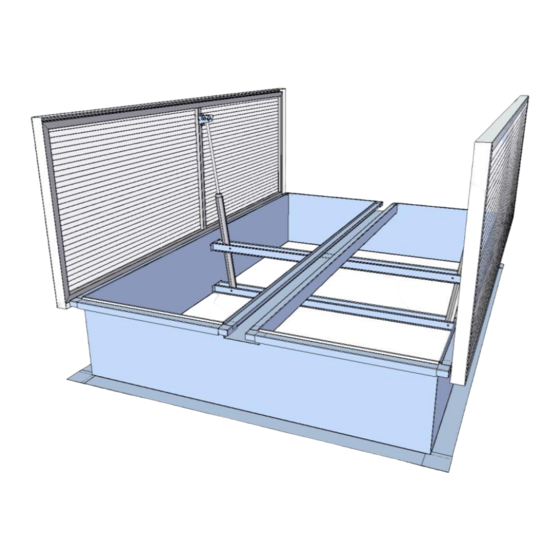
mcr-PROLIGHT vents : DVP, DVPS TYPE PERATION AND MAINTENANCE MANUAL 9. INSTALLATION OF CONTROL DELIVERED SEPARATELY If the control system is delivered separately, perform the installation as shown below. A. Place the cross-bar in the flap base (along its axis), at height shown on the appended drawing of the control system. -
Page 27: Vents Maintenance
Periodical maintenance works and service inspections are required on the installed devices. These are performed by MERCOR S.A. authorized service. The service interval is 6 months. The following actions are required from the user between inspections. -
Page 28: Warranty And Service Terms
MERCOR S.A. grants a 12-month quality warranty for the equipment, counted from the purchase date, unless the agreement provides otherwise. MERCOR S.A. declares to remove, within 21 days counted from the date of receiving a written claim, save for item 5, any physical defects in equipment identified within the warranty period. -
Page 29: Certificates Of Conformity
mcr-PROLIGHT vents : DVP, DVPS TYPE PERATION AND MAINTENANCE MANUAL 12. CERTIFICATES OF CONFORMITY Page 29 of 30... - Page 30 mcr-PROLIGHT vents : DVP, DVPS TYPE PERATION AND MAINTENANCE MANUAL Page 30 of 30...
Need help?
Do you have a question about the mcr-PROLIGHT DVP and is the answer not in the manual?
Questions and answers