Table of Contents
Advertisement
Quick Links
SF000 LiDAR Sensor
Product guide
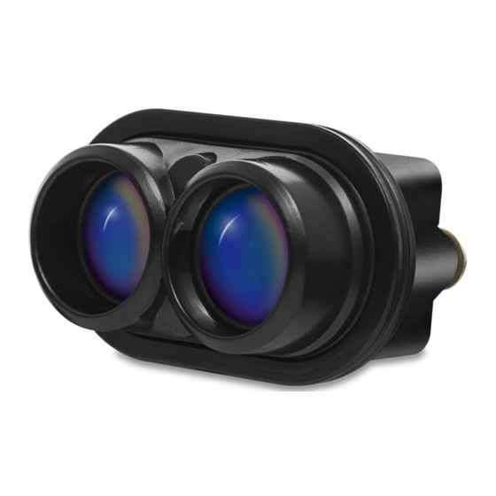
SF000 LiDAR sensor
MicroLiDAR for obstacle detection
Disclaimer
Information found in this document is used entirely at the reader's own risk and whilst every effort has
been made to ensure its validity, neither LightWare Optoelectronics (Pty) Ltd nor its representatives make
any warranties with respect to the accuracy of the information contained herein.
1 of 47
SF000 microLiDAR™ sensor - Product guide(Rev 5) | © LightWare Optoelectronics (Pty) Ltd, 2021 |
www.lightwarelidar.com
Advertisement
Table of Contents

Subscribe to Our Youtube Channel
Related Manuals for Lightware SF000


Summary of Contents for Lightware SF000
- Page 1 LightWare Optoelectronics (Pty) Ltd nor its representatives make any warranties with respect to the accuracy of the information contained herein. 1 of 47 SF000 microLiDAR™ sensor - Product guide(Rev 5) | © LightWare Optoelectronics (Pty) Ltd, 2021 | www.lightwarelidar.com...
-
Page 2: Overview
Using a time-of-flight system to make very fast, accurate distance measurements. Accuracy is not affected by the colour or texture of the surface, nor the angle of incidence of the laser beam. The SF000/B is virtually immune to background light, wind and noise, making it an ideal sensor to detect unexpected obstacles. -
Page 3: Table Of Contents
Packets Checksum Receiving packets Handling request & response I2C interface Overview Command list Command descriptions 0. Product name 1. Hardware version 3 of 47 SF000 microLiDAR™ sensor - Product guide(Rev 5) | © LightWare Optoelectronics (Pty) Ltd, 2021 | www.lightwarelidar.com... - Page 4 83. Median filter size 84. Smoothing filter enable 85. Smoothing factor 93. Rolling average enable 94. Rolling average size Document revision 4 of 47 SF000 microLiDAR™ sensor - Product guide(Rev 5) | © LightWare Optoelectronics (Pty) Ltd, 2021 | www.lightwarelidar.com...
-
Page 5: Specifications
Servo driver SDA (I2C data line must be used with pin 4) TXD/SCL (Serial/I2C) RXD/SDA (Serial/I2C) +5V (4.5V - 5V operating range) 5 of 47 SF000 microLiDAR™ sensor - Product guide(Rev 5) | © LightWare Optoelectronics (Pty) Ltd, 2021 | www.lightwarelidar.com... -
Page 6: Quickstart Guide
Insert the communication cable into the SF000/B and a serial to USB adaptor**. You will need a serial to USB adaptor to connect the SF000/B to a computer. Any serial TTL 3.3 V USB adaptor will work, this guide uses one available from LightWare LLC here. - Page 7 Windows users: Please wait for Windows to install the generic communication driver after connecting the SF000/B for the first time. Run LightWare Studio. You will be presented with a home screen that shows devices connected to your computer. Your USB adaptor will be recognized and displayed here.
- Page 8 LightWare Studio device information screen Click on the Upgrade tool in the left panel. It is recommended to make sure your SF000/B has the latest firmware. You can see the changes that have been made to each version, and the option of downgrading is also available. If you choose to upgrade, then click the Install button and follow the instructions.
- Page 9 SF000 LiDAR Sensor Product guide Click the Distance tool in the left panel. This tool shows you distance readings gathered by the SF000/B. Feel free to point the SF000/B at various surfaces to measure their distances. LightWare Studio SF000/B scanning screen 9 of 47 SF000 microLiDAR™...
- Page 10 Parameters are shown in the panel on the top right of the LightWare Studio window. Modify these parameters to fit your application. LightWare Studio SF000/B scanning parameters For a detailed breakdown on what the parameters do and how they affect the operation of the SF000/B, see the operating concepts section.
-
Page 11: Package Contents
2 x Communication cable (Digikey: 455-3238-ND) 5 x M3 x 12 SS Cap Screw 5 x M3 SS Hex Nut 5 x M3 SS Washer 11 of 47 SF000 microLiDAR™ sensor - Product guide(Rev 5) | © LightWare Optoelectronics (Pty) Ltd, 2021 | www.lightwarelidar.com... -
Page 12: Hardware
SF000 LiDAR Sensor Product guide Hardware Dimensions SF000/B dimensions Components SF000/B view from above and below 12 of 47 SF000 microLiDAR™ sensor - Product guide(Rev 5) | © LightWare Optoelectronics (Pty) Ltd, 2021 | www.lightwarelidar.com... -
Page 13: Optical Assembly
The optical assembly is comprised of the laser and receiver lenses. SF000/B optical assembly Heatsink & EMI shield The shield lowers EMI radiation entering or leaving the SF000/B. It also acts as a heatsink to draw heat away from the SF000/B. SF000/B shield 13 of 47 SF000 microLiDAR™... -
Page 14: Connectors & Indicators
Please note that when connecting to the device using I2C, both pins 2 and 4 need to be used together as the SDA line. 14 of 47 SF000 microLiDAR™ sensor - Product guide(Rev 5) | © LightWare Optoelectronics (Pty) Ltd, 2021 | www.lightwarelidar.com... -
Page 15: Installation
Make sure the SF000/B is functional before installation. You can use LightWare Studio to verify operation. See the quick start with LightWare Studio for details. The SF000/B requires a clear line-of-sight to measure distance to a target surface. It can be mounted with a vertical or horizontal lens orientation. SF000/B mounting orientations... - Page 16 SF000 LiDAR Sensor Product guide The SF000/B includes a mounting bracket and mounting hardware which can be used to securely attach the LiDAR to the required surface. Mounting bracket installed onto the SF000/B Take note: Make sure the SF000/B is securely mounted to prevent false readings or damage.
-
Page 17: Operating Concepts
48 Hz to 388 Hz. The SF000/B can be connected to a host controller with the serial or I2C interface. The serial port (3.3 V logic level, 5 V tolerant) has a configurable baud rate. The I2C serial bus (3.3 V logic level and 3.3 k pull up resistors, 5 V tolerant) has a configurable address and is an alternative to the serial port when multiple devices are connected on a... -
Page 18: Parameters
SF000 LiDAR Sensor Product guide Parameters SF000/B parameters can be adjusted with LightWare Studio or from the platform of your choice through the serial or I2C communication interfaces. LightWare Studio parameters screen 18 of 47 SF000 microLiDAR™ sensor - Product guide(Rev 5) | © LightWare Optoelectronics (Pty) Ltd, 2021 |... - Page 19 Enable smoothing filter The smoothing filter is used to remove noise from the measurements. Smoothing filter strength Determines response of the smoothing filter. 19 of 47 SF000 microLiDAR™ sensor - Product guide(Rev 5) | © LightWare Optoelectronics (Pty) Ltd, 2021 | www.lightwarelidar.com...
-
Page 20: Firmware Change Log
Follow the Quick start with LightWare Studio guide for details on downloading and using LightWare Studio. 1.2.0 Notes: Initial release. ● 20 of 47 SF000 microLiDAR™ sensor - Product guide(Rev 5) | © LightWare Optoelectronics (Pty) Ltd, 2021 | www.lightwarelidar.com... -
Page 21: Safety & Maintenance
Laser emitting lens The SF000/B is rated laser Class 1M eye safe. Class 1M laser is safe for all conditions of use however it is not safe to view the laser through magnifying optics such as microscopes, binoculars or telescopes. -
Page 22: Electrical Safety
Ensure that there is adequate airflow permitted for the sensor. ● The mechanical dimensions for mounting the SF000/B are provided in the hardware overview. ● 22 of 47 SF000 microLiDAR™ sensor - Product guide(Rev 5) | © LightWare Optoelectronics (Pty) Ltd, 2021 | www.lightwarelidar.com... -
Page 23: Laser Radiation Information
Approximate values only. Please contact LightWare LLC if further information is required. Service & maintenance The SF000/B is not field serviceable. For any repairs, the equipment should be completely isolated, removed then packaged carefully. Please visit LightWare LLC’s refund policy... -
Page 24: Serial Interface
Communication is performed using encapsulated packets for both sending and receiving data. Every packet that is sent to the SF000/B is known as a request and a correctly formatted request will always be replied to with a response. There are cases where the SF000/B will send a request packet to the host, these packets are considered streaming packets as they arrive without a direct request from the host - they do not require a response from the host. -
Page 25: Packets
Each packet has a 2 byte checksum which is used to validate data integrity. The algorithm is CRC-16-CCITT 0x1021. The CRC must be correctly formed for the SF000/B to accept and process packets. Below are some examples in various languages for CRC calculation: 25 of 47 SF000 microLiDAR™... - Page 26 ^= code; code = code << & 0xFFFF; crc ^= code; code = code << & 0xFFFF; crc ^= code; return crc; 26 of 47 SF000 microLiDAR™ sensor - Product guide(Rev 5) | © LightWare Optoelectronics (Pty) Ltd, 2021 | www.lightwarelidar.com...
-
Page 27: Receiving Packets
Here is the process for reading the raw serial byte stream and identifying packets. Once a packet has been successfully read it can be processed based on its command ID. 27 of 47 SF000 microLiDAR™ sensor - Product guide(Rev 5) | © LightWare Optoelectronics (Pty) Ltd, 2021 | www.lightwarelidar.com... -
Page 28: Handling Request & Response
Handling request & response Every request sent to the SF000/B will receive a response, it is often useful to use the response as a way to determine if the request was received and processed. Here is the recommended procedure for sending a command request and reading the response: The values used for timeout or number of retries should be tuned to the specific application. -
Page 29: I2C Interface
We suggest using the pre-built APIs for communicating with the SF000/B where possible. The SF000/B uses a packet based binary protocol which can be accessed over the serial and I2C interfaces. All higher level APIs (C, Python, JavaScript) use this protocol to function. -
Page 30: Command List
SF000 LiDAR Sensor Product guide Command list If a command is not readable or writable then it can only be received from the SF000/B and not sent to it. Name Description Read Write Persists bytes bytes Product Product name name... - Page 31 filter enable smoothing filter Smoothing Strength factor smoothing filter Rolling Enables rolling average average enable Rolling Size rolling average size average 31 of 47 SF000 microLiDAR™ sensor - Product guide(Rev 5) | © LightWare Optoelectronics (Pty) Ltd, 2021 | www.lightwarelidar.com...
-
Page 32: Command Descriptions
0. Product name indicating the product model name. This will always be followed by 16 byte string SF000/B a null terminator. You can use this to verify the SF000/B is connected and operational over the selected interface. Read Write Persists... -
Page 33: Serial Number
Write Persists byte string 7. UTF8 text message Serial interface only A null terminated ASCII string. The SF000/B will send this command when it needs to communicate a human readable message. Read Write Persists 9. User data This command allows 16 bytes to be stored and read for any purpose. -
Page 34: Token
Read Write Persists uint1 14. Reset Writing the safety to this command will restart the SF000/B. token Read Write Persists uint1 34 of 47 SF000 microLiDAR™ sensor - Product guide(Rev 5) | © LightWare Optoelectronics (Pty) Ltd, 2021 | www.lightwarelidar.com... -
Page 35: Distance Output
First return strength Last return raw Last return filter Last return strength Background noise Temperature Yaw angle Read Write Persists uint32 uint3 35 of 47 SF000 microLiDAR™ sensor - Product guide(Rev 5) | © LightWare Optoelectronics (Pty) Ltd, 2021 | www.lightwarelidar.com... -
Page 36: Stream
Stream command over I2C, the resulting streamed data will not be retrievable. Read Write Persists uint32 uint3 36 of 47 SF000 microLiDAR™ sensor - Product guide(Rev 5) | © LightWare Optoelectronics (Pty) Ltd, 2021 | www.lightwarelidar.com... -
Page 37: Distance Data In Cm
Last return strength [%] int16 Background noise int16 Temperature [1/100 degC] int16 Yaw angle [1/100 deg] int16 Read Write Persists varies 37 of 47 SF000 microLiDAR™ sensor - Product guide(Rev 5) | © LightWare Optoelectronics (Pty) Ltd, 2021 | www.lightwarelidar.com... -
Page 38: Distance Data In Mm
Product guide 45. Distance data in mm This command contains distance data as measured by the SF000/B. The data included will vary based on the configuration of the 27. Distance output command. The data will be packed in order based on the bits set in the Distance output parameter. -
Page 39: Laser Firing
Persists uint8 uint8 57. Temperature Reading this command will return the temperature in 100ths of a degree. Read Write Persists uint32 39 of 47 SF000 microLiDAR™ sensor - Product guide(Rev 5) | © LightWare Optoelectronics (Pty) Ltd, 2021 | www.lightwarelidar.com... -
Page 40: Update Rate
The update rate is selected from the following table: Command value Update rate samples/second Read Write Persists uint8 uint8 40 of 47 SF000 microLiDAR™ sensor - Product guide(Rev 5) | © LightWare Optoelectronics (Pty) Ltd, 2021 | www.lightwarelidar.com... -
Page 41: Noise
The lost signal indication on the distance output value is -1000. Read Write Persists uint32 uint3 41 of 47 SF000 microLiDAR™ sensor - Product guide(Rev 5) | © LightWare Optoelectronics (Pty) Ltd, 2021 | www.lightwarelidar.com... -
Page 42: Baud Rate
Reading this command will return the baud rate. Writing to this command will set the baud rate. Value Baud rate [bps] 9600 19200 38400 57600 115200 230400 460800 921600 Read Write Persists uint8 uint8 42 of 47 SF000 microLiDAR™ sensor - Product guide(Rev 5) | © LightWare Optoelectronics (Pty) Ltd, 2021 | www.lightwarelidar.com... -
Page 43: I2C Address
Reading this command will return the status of the median filter. Writing this command will set the status of the median filter. Value Description disabled enabled Read Write Persists uint8 uint8 43 of 47 SF000 microLiDAR™ sensor - Product guide(Rev 5) | © LightWare Optoelectronics (Pty) Ltd, 2021 | www.lightwarelidar.com... -
Page 44: Median Filter Size
Reading this command will return the status of the smoothing filter. Writing this command will set the status of the smoothing filter. Value Description disabled enabled Read Write Persists uint8 uint8 44 of 47 SF000 microLiDAR™ sensor - Product guide(Rev 5) | © LightWare Optoelectronics (Pty) Ltd, 2021 | www.lightwarelidar.com... -
Page 45: Smoothing Factor
Reading this command will return the status of the rolling average filter. Writing this command will set the status of the rolling average filter. Value Description disabled enabled Read Write Persists uint8 uint8 45 of 47 SF000 microLiDAR™ sensor - Product guide(Rev 5) | © LightWare Optoelectronics (Pty) Ltd, 2021 | www.lightwarelidar.com... -
Page 46: Rolling Average Size
filter. The valid range is 2 to 32. Read Write Persists uint32 uint3 46 of 47 SF000 microLiDAR™ sensor - Product guide(Rev 5) | © LightWare Optoelectronics (Pty) Ltd, 2021 | www.lightwarelidar.com... -
Page 47: Document Revision
FDA accession number added,notification that I2C pins 2 and 4 need to be used as for SDA Rev 0 2020/08/03 First edition 47 of 47 SF000 microLiDAR™ sensor - Product guide(Rev 5) | © LightWare Optoelectronics (Pty) Ltd, 2021 | www.lightwarelidar.com...
Need help?
Do you have a question about the SF000 and is the answer not in the manual?
Questions and answers