Table of Contents
Advertisement
Quick Links
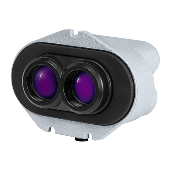
LW24 LiDAR sensor
MicroLiDAR for obstacle detection
Disclaimer
Information found in this document is used entirely at the reader's own risk and whilst every effort has been made to ensure
its validity, neither LightWare Optoelectronics (Pty) Ltd nor its representatives make any warranties with respect to the
accuracy of the information contained herein.
LW24/C/SI microLiDAR™ sensor - Product guide
|
Version
0|
03 March 2022
Page 1 of 36
Advertisement
Table of Contents

Related Manuals for Lightware LW24 LiDAR


Summary of Contents for Lightware LW24 LiDAR
- Page 1 Information found in this document is used entirely at the reader’s own risk and whilst every effort has been made to ensure its validity, neither LightWare Optoelectronics (Pty) Ltd nor its representatives make any warranties with respect to the accuracy of the information contained herein.
-
Page 2: Table Of Contents
Table of contents Overview Product support Specifications Quickstart guide Package contents The LW24/C box includes: Dimensions Components Optical assembly Heatsink & EMI shield Connectors & indicators Communication cable pinout Installation Mounting Operating concepts Distance measuring Serial port baud rate Startup mode I2C address I2C bus speed Update rate... - Page 3 Service & maintenance Cleaning Serial interface Packets Checksum C/C++ JavaScript Receiving packets Handling request & response I2C interface Overview Command list Command descriptions 0. Product name 1. Hardware version 2. Firmware version 3. Serial number 7. UTF8 text message 9. User data 10.
- Page 4 93. Rolling average enable 94. Rolling average size Document revision LW24/C/SI microLiDAR™ sensor - Product guide Version 0 03 March 2022 Page 4 of 36...
-
Page 5: Overview
28.7 g / 1.01oz (excluding cables) Enclosure rating IP67 Optical Approvals FDA: 1710193-000 (2020/09) Laser safety Class 1M (refer to www. lightware.co.za/safety for full details) Optical aperture 10 mm Beam divergence < 0.5° Environmental Operating temperature -10 ... + 50°C / 14 … 122 °F LW24/C/SI microLiDAR™... -
Page 6: Quickstart Guide
48 readings per second Quickstart guide LightWare Studio is an application (available for Windows, macOS, and Linux) that can configure, update, and visualize data for the LW24/C. In this guide we will use LightWare Studio to view distance data from the LW24/C. - Page 7 Windows users: Please wait for Windows to install the generic communication driver after connecting the LW24/C for the first time. Run LightWare Studio. You will be presented with a home screen that shows devices connected to your computer. Your USB adaptor will be recognized and displayed here.
- Page 8 LightWare Studio device information screen Click on the Upgrade tool in the left panel. It is recommended to make sure your LW24/C has the latest firmware. You can see the changes that have been made to each version, and the option of downgrading is also available. If you choose to upgrade, then click the Install button and follow the instructions.
- Page 9 LW24/C at various surfaces to measure their distances. LightWare Studio LW24/C scanning screen. Parameters are shown in the panel on the top right of the LightWare Studio window. Modify these parameters to fit your application. LW24/C/SI microLiDAR™ sensor - Product guide...
- Page 10 LightWare Studio LW24/C scanning parameters. For a detailed breakdown on what the parameters do and how they affect the operation of the LW24/C, see the operating concepts section. What's next? The next step is to integrate the LW24/C into your platform of choice. Please follow one of the integration guides, or consult the communication protocol reference for building your own system to interact with the LW24/C.
-
Page 11: Package Contents
Package contents The LW24/C box includes: Tensility straight DigiKey: Optional: 1 x LW24/C MicroLiDAR unit 839-1553-ND Tensility 90 degree DigiKey: 839-10-03635-ND 5 x M2 hex nut 5 x Flat washer 5 x M2 x 12 Pan slotted screw) Hardware Dimensions LW24/C dimensions LW24/C/SI microLiDAR™... -
Page 12: Components
Components LW24/C view from above and below Optical assembly The optical assembly comprises the laser and receiver lenses. LW24/C optical assembly Heatsink & EMI shield The lid lowers EMI radiation entering or leaving the LW24/C. It also acts as a heatsink to draw heat away from the LW24/C. -
Page 13: Connectors & Indicators
LW24/C shield Connectors & indicators LW24/C connectors & indicators Communication cable pinout Communication cable pinout Function Notes 4.5 V … 5.5 V, 55mA I(typical) RXD/SDA RXD when using Serial, SDA when using I2C. TXD/SCL TXD when using Serial, SCL when using I2C. Ground LW24/C/SI microLiDAR™... -
Page 14: Installation
Installation Mounting Make sure the LW24/C is functional before installation. You can use LightWare Studio to verify operation. See the quick start with LightWare Studio for details. The LW24/C requires a clear line-of-sight to measure distance to a target surface. It can be mounted with a vertical or horizontal lens orientation. -
Page 15: Operating Concepts
The I2C serial bus (3.3 V logic level and 3.3 k pull up resistors, 5 V tolerant) has a configurable address and is an alternative to the serial port when multiple devices are connected on a common bus. LightWare Studio showing measurements from the LW24/C LW24/C/SI microLiDAR™ sensor - Product guide... -
Page 16: Serial Port Baud Rate
Parameters LW24/C parameters can be adjusted with LightWare Studio or from the platform of your choice through the serial or I2C communication interfaces. LightWare Studio parameters screen Serial port baud rate Controls the baud rate used by the serial UART interface in kbps. -
Page 17: Lost Signal Threshold
Determines response of the smoothing filter. Firmware change log Upgrading firmware The LW24/C firmware can be upgraded by using LightWare Studio. Download LightWare Studio here. Follow the Quick start with LightWare Studio guide for details on downloading and using LightWare Studio. -
Page 18: Laser Eye Safety
LightWare LLC assumes no liability for failure to comply with these requirements. The LW24/C is not field serviceable. For any repairs, the equipment should be completely isolated, removed then packaged carefully. -
Page 19: Electrical Safety
NOHD 15 m may be used safely. Approximate values only. Please contact LightWare LLC if further information is required. Service & maintenance The LW24/C is not field serviceable. For any repairs, the equipment should be completely isolated, removed then packaged carefully. Please visit LightWare LLC’s refund... -
Page 20: Serial Interface
Serial interface Overview We suggest using the pre-built APIs for communicating with the LW24/C where possible. The LW24/C uses a packet based binary protocol which can be accessed over the serial and I2C interfaces. All higher-level APIs (C, Python, JavaScript) use this protocol to function. If you require more control than the existing APIs offer or need to port the protocol to a different platform, then you can use the information here to build a compatible system. -
Page 21: Checksum
The Start byte is always 0xAA and indicates the beginning of a packet. It is important to verify that the payload length is between (inclusive) 0 to 1023 and that the checksum is valid before processing a packet, rather than just relying on the start byte. -
Page 22: Receiving Packets
for (let i = 0; i < size; ++i) { let code = crc >>> & 0xFF; code ^= data[i] & 0xFF; code ^= code >>> 4; crc = crc << & 0xFFFF; crc ^= code; code = code << &... -
Page 23: Handling Request & Response
If the packet length or checksum is invalid, then it is technically more correct to roll the incoming stream back to when the start byte was found. However, in practice this has little appreciable impact. Handling request & response Every request sent to the LW24/C will receive a response, it is often useful to use the response to determine if the request was received and processed. -
Page 24: I2C Interface
The values used for timeout or number of retries should be tuned to the specific application. I2C interface Overview We suggest using the pre-built APIs for communicating with the LW24/C where possible. The LW24/C uses a packet based binary protocol which can be accessed over the serial and I2C interfaces. All higher-level APIs (C, Python, JavaScript) use this protocol to function. - Page 25 If you require more control than the existing APIs offer or need to port the protocol to a different platform, then you can use the information here to build a compatible system. The LW24/C will always be the slave on the I2C interface. Therefore, data will only be transmitted when requested by the master.
-
Page 26: Command List
Command list If a command is not readable or writable then it can only be received from the LW24/C and not sent to it. Name Description Read bytes Write bytes Persists Product name Product name Hardware version Hardware revision Firmware version Firmware revision Serial number Serial number... -
Page 27: Command Descriptions
Set number of lost signal Lost signal counter conditions Baud rate Serial baud rate I2C address I2C address Median filter Enable/disable the enable median filter Set median filter Set the median filter size size Smoothing filter Enable/disable the enable median filter Set smoothing Set the smoothing filter factor... -
Page 28: Serial Number
3. Serial number A 16 byte string (null terminated) of the serial identifier assigned during production. Read Write Persists 16 bytes 7. UTF8 text message Serial interface only A null terminated ASCII string. The LW24/C will send this command when it needs to communicate a human readable message. -
Page 29: Stage Firmware
16. Stage firmware The first part of uploading firmware to the LW24/C is to stage the data. This command accepts pages of the firmware, each 128 bytes long, and an index to indicate which page is being uploaded. Pages are created by dividing the firmware upgrade file into multiple 128 byte chunks. -
Page 30: Distance Output
Once the firmware is committed, a reboot is required to engage the new firmware. This can be done by cycling power to the LW24 or by sending the 14. Reset command. After the unit has rebooted the firmware version should be checked to ensure the new firmware is installed. Read Write Persists... -
Page 31: Distance Data In Cm
Read Write Persists uint32 uint32 44. Distance data in cm This command contains distance data as measured by the LW24/C. The data included will vary based on the configuration of the 27. Distance output command. This command can be read at any time however if 30. -
Page 32: Laser Firing
Last return strength [%] int32 Background noise int32 Temperature [1/100 degC] int32 Read Write Persists varies 50. Laser firing Reading this command will indicate the current laser firing state. Writing to this command will enable or disable the firing of the laser. Value Description Disabled... -
Page 33: Noise
Read Write Persists uint8 uint8 74. Noise Reading this command will return the level of background noise. Read Write Persists uint32 75. Zero offset Changing this offset value will change the Zero distance position for the output. This value is written and read in mm. Read Write Persists... -
Page 34: I2C Address
Read Write Persists uint8 uint8 80. I2C address Reading this command will return the I2C address. Writing this command will set the I2C address. The I2C address value is in decimal. Read Write Persists uint8 uint8 82. Median filter enable Reading this command will return the status of the median filter. -
Page 35: Smoothing Factor
enabled Read Write Persists uint8 uint8 85. Smoothing factor Reading this command will return the strength of the smoothing filter. Writing this command will set the strength of the smoothing filter. The valid range is 0 to 100. Read Write Persists Uint32 Uint32... - Page 36 Document revision Revision Date Comments Rev 0 2022/03/03 First edition LW24/C/SI microLiDAR™ sensor - Product guide Version 0 03 March 2022 Page 36 of 36...
Need help?
Do you have a question about the LW24 LiDAR and is the answer not in the manual?
Questions and answers