Table of Contents
Advertisement
Quick Links
Advertisement
Table of Contents

Related Manuals for Heras HMD230


Summary of Contents for Heras HMD230
- Page 1 User Manual Gate with drive HMD230 HGD230 IGD230 Please read this original user manual before using this gate for the first time! Act in accordance with the manual and keep it in a safe place for later use or for the following owner.
- Page 2 EN – Translation of the original user manual - 2.1 | 2019...
-
Page 3: Table Of Contents
CONFORMITY WITH EUROPEAN DIRECTIVES ..........10 DELIVERY ....................10 GENERAL INFORMATION REGARDING THE ELECTRICAL CONNECTIONS ..... 11 DELIVERY OF DRIVE UNIT ................11 HMD230 / HGD230 ..................11 1.10 IGD230 ....................12 SAFETY ......................13 EXPLANATION OF THE SYMBOLS ..............13 SAFETY DISTANCES ................... - Page 4 4.11 AUTOMATICALLY CHANGING OPERATING MODES ........30 CONTROL UNIT AND DISPLAY READINGS ............ 32 TOTAL VIEW OF HMD230 DRIVE UNIT ............32 TOTAL VIEW OF HGD230/IGD230 DRIVE UNIT ..........32 VIEW OF CONTROL UNIT ................33 TWIST AND SELECTOR SWITCH ..............34 LCD SCREEN....................
- Page 5 6.3.2 Connecting the ISK system ..............56 6.3.3 Connecting a photocell ................. 56 6.3.4 Wiring diagram for the inputs on the terminal block ......... 57 6.3.5 Incremental encoder ................57 RELAY OUTPUT CONNECTIONS..............58 6.4.1 Relay output with 24 V ...............
- Page 6 7.19 SUPPORT DURING DIAGNOSIS ..............82 7.19.1 Version display ..................82 7.19.2 Movement commands at start-up ............83 7.19.3 Gate status ..................83 7.19.4 Sensor statuses ................... 85 7.19.5 Temperatures ..................85 7.19.6 Log system ..................85 7.20 REMOTE CONTROL .................. 86 7.20.1 Displaying the number of hand transmitters ..........
- Page 7 SLIDING GATE DESCRIPTION ..............110 13.2 DRIVE DESCRIPTION ................110 APPENDIX A: DECLARATIONS DOP / DOC ............112 APPENDIX B: ELECTRIC DIAGRAM HMD230/HGD230 ........115 APPENDIX C: ELECTRIC DIAGRAM IGD230 ............129 EN – Translation of the original user manual - 2.1 | 2019...
-
Page 8: Foreword
The installer uses an installation scheme for the drive concerned and works according to the applicable standards. In the event of a fault, you should contact a Heras certified technician. EN – Translation of the original user manual - 2.1 | 2019... -
Page 9: Preface
Operators are not allowed to carry out any installation work on the gate unless explicitly specified. Engineer: The engineer is a Heras fitter (or an engineer employed by the customer who has been given explicit permission in writing from Heras) who is qualified to perform technical interventions on the gate. -
Page 10: Prescribed Use / Application
PRESCRIBED USE / APPLICATION Only the correct installation and maintenance by an authorised/qualified company or person in agreement with the user manual, logbook, checklists and maintenance lists can ensure the safe operation of the system. A qualified person is, according to EN 12635, a person who has the required training, qualified knowledge and practical experience required to install, test and maintain a sliding gate system correctly and safely. -
Page 11: General Information Regarding The Electrical Connections
After installation and commissioning, by a Heras technician or a technician trained by Heras, the cover of the HMD230/HGD230 and IGD drive unit must be locked with a key. This key is then handed over to the customer. This is done to prevent unauthorised access. -
Page 12: Igd230
Illustration 1: HGD230 cover, cabinet and gear wheel Illustration 2: HGD230 cover, cabinet and gear wheel 1.10 IGD230 The IGD230 is delivered as a complete drive and control unit, including gear wheel module 6. The drive is only delivered together with the iGate. By default, the half profile cylinder (according to DIN 18252) is not included. -
Page 13: Safety
It is forbidden to apply the drive unit to gates other than those stated in • this manual, without Heras' permission. Applying a third-party drive unit and/or safety edge may affect safety and • will invalidate the CE mark. -
Page 14: Safety Provisions Employed
The HMD230 is a frequency converter. Since dangerous live voltage may still be present after switching off the HMD230, you must observe a 3 to 5 minute waiting time to make sure that all power has discharged. Working on a live frequency converter PCB involves... -
Page 15: Intended Use
INTENDED USE The gate is intended to control access to a specific plot, premises or site. The gate is intended for both industrial and private use. The gate drive and control unit is adjusted to the options agreed with the user. The relevant options are laid down during hand-over. -
Page 16: Safety During Installation, Maintenance And Disassembly
This can lead to serious injury. Therefore, it is prohibited to drill into or grind these rails. !! Only people trained by Heras are allowed to disassemble the bottom rail. If the gate is damaged, always contact the supplier for an inspection. - Page 17 Illustration 4: Warning sticker bottom rail EN – Translation of the original user manual - 2.1 | 2019...
-
Page 18: Operation
OPERATION OPENING/CLOSING SLIDING GATE - NORMAL USE The gate can be operated using pulse operation, for instance via a button or key switch. The location of the operating device depends on the customer's choice or the operating mode. • OPEN: Press the “Open”... -
Page 19: Closing The Cover
Close the lever and the lock. • Illustration 6: closing the cover* * The illustration shows the HMD230. The same principle applies to the HGD230 and IGD230. 3.2.3 Open / close in case of emergency Two push buttons are located on the backplane of the control unit. These can be used to open, close and stop the gate. -
Page 20: Disengaging The Motor
3.2.4 Disengaging the motor The gate can be opened by hand in emergency situations. The gear wheel of the drive unit will have to be disengaged from the toothed bar for this. Open the drive unit cabinet (key) • Set the automatic fuse to “OFF”. •... -
Page 21: Automatic Disengagement
AUTOMATIC DISENGAGEMENT Versions with automatic disengagement if there is a power failure can be recognized by a coil; this will automatically disengage the drive if a power failure occurs. Illustration 10: Automatic disengagement Attention! To be able to use the electrical system again to operate the gate after operating it manually, follow the procedure as described in chapter EN –... -
Page 22: Description
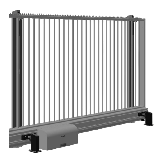
HMD230 bottom rail motor bracket bottom rail slam support head stile running surface running wheels running surface... -
Page 23: Ugate
UGATE The uGate is a cantilever sliding gate with a modular structure for openings up to 12 meters in a single version and up to 24 meters in a double version. Applications include port areas, company buildings, office buildings, storage sites, garden and landscape areas, high-risk sites, airports, transport and distribution sites, and parking garages. -
Page 24: Shb
Applications include harbor areas, company buildings, storage sites, high-risk sites, airports, and transport and distribution sites. guidepost safety edge bars HMD230 bottom rail slam post Illustration 14: SHB sliding gate terms EN – Translation of the original user manual - 2.1 | 2019... -
Page 25: Safeglide 2
Applications include harbor areas, company buildings, storage sites, high-risk sites, airports, and transport and distribution sites. Guide column bars slam post HMD230 bottom rail Illustration 15: SafeGlide 2 sliding gate terms DRIVE UNIT 4.6.1 Drive unit variants The following sliding gate/drive unit combinations are possible:... -
Page 26: Safety Edges
E = Excellent See the chapter "TECHNICAL DATA" for further information. The motor of the HMD230/IGD has a pulse generator enabling the motor control to determine the gate position. It is already connected to the control unit on delivery. Limit switches are not necessary anymore. -
Page 27: Accessoires
4.9.5 Lighting (optional*) Two kinds of lighting can be connected to the HMD230. Passage lighting to enhance the visibility of the passage opening. It can •... -
Page 28: Led Lighting In Top Rail (Optional)
Outdoor lighting to illuminate the grounds. This is activated as soon as • the gate is operated and it is switched off automatically after a certain pre-set time. * In some countries, lighting is obligatory. 4.9.6 Led lighting in top rail (optional) The iGate can optionally be fitted with LED lighting in the top rail. -
Page 29: Automatic Mode
(depending on the type, HMD230/HGD230/IGD230), this will be 0.25 m/s or 0.5 m/s). If the power supply to the drive has been interrupted, the gate will also only run at dead man's mode speed until the first time when an end position has been reached. -
Page 30: Emergency Operation
AUTOMATICALLY CHANGING OPERATING MODES The gate motor drive can switch over from automatic mode to emergency operation if it has been programmed to allow this and the HMD230/IGD recognizes a corresponding "emergency situation" signal from a fire emergency room. This operating mode will then be performed until the motor drive is restarted. - Page 31 Hold-to-run-control mode -> Automatic mode (if safety has been • restored) • Automatic mode -> Emergency operation Emergency operation -> Automatic mode (if no emergency • situation signal is active anymore and after restarting the control software) EN – Translation of the original user manual - 2.1 | 2019...
-
Page 32: Control Unit And Display Readings
Control unit place for extra components automatic fuse backplane cable strain relief motor cable bushing Illustration 16: view of HMD230 drive unit TOTAL VIEW OF HGD230/IGD230 DRIVE UNIT place for extra components timer (optional) control unit backplane place for extra... -
Page 33: View Of Control Unit
VIEW OF CONTROL UNIT Illustration 18: view of control unit EN – Translation of the original user manual - 2.1 | 2019... -
Page 34: Twist And Selector Switch
The twist and selector switch, located under the battery for the clock, enables the information displayed by the HMD230 to be influenced. This twist and selector switch can also be used to control the manual programming of the motor drive using the integrated menu system. -
Page 35: Lcd Screen
Display reading Meaning ATC Pe:x.xx Start indication of the periphery controller (wait for information from the motor controller) Heras HMD230 Automatic operating mode, the gate is now in the idle Automatic mode position Automatic mode Automatic mode; gate opening active... -
Page 36: Date And Time Display
Display reading Meaning Hold-to-run- Close gate in hold-to-run-control mode active control Hold-to-run- Hold-to-run-control STOP active control Heras HMD230 Idle position for emergency operation Emergency Emergency Emergency operation; gate opening active operation Open Emergency Emergency operation; gate closing active operation Close Emergency Emergency operation;... -
Page 37: Display Errors/Events
Sensors that are not installed (specified by parameters in the program) are also not displayed. Display reading Meaning No sensors Is shown if no sensors have been programmed Turn the selector switch in a counter-clockwise Sensors Begin direction to access the first entry in the sensor Pulse generator Current value of the incremental encoder value:... -
Page 38: Selecting The Menu System
2 seconds, "161 Immediate stop" is displayed. 5.5.5 Selecting the menu system The HMD230 menu system is accessed by pressing the twist and selector switch for approx. 2 seconds while the operating mode is displayed. The display then shows the text "Main menu". - Page 39 initially shows "Automatic mode" and after the twist and selector switch is pressed for two seconds and released again the menu display changes. The following will then be displayed: Main menu 1 Identification Turning the selector one position further in a clockwise direction displays the following information: Main menu 2 Service Menu...
-
Page 40: Menu Display Instructions
When this menu option is selected, the motor drive will restart the program (reset) and the active operating mode will be switched on again (here: "Automatic mode"). MENU DISPLAY INSTRUCTIONS The menu system of the HMD230 offers the following possibilities: 1. Identification Master version Motor drive software version ... - Page 41 In-/Outputs Choice of functions for Inputs IN5 and IN6 as well as the outputs Rel4 and Rel5 Safeties Settings for the installed safeties Special parameters Settings for maintenance notifications Operating mode Choice between hold to run and automatic control ...
-
Page 42: Menu Structure , Texts And References
MENU STRUCTURE , TEXTS AND REFERENCES Selecting the menu brings you to the main menu level where you can choose from a number of submenus. The first menu option "Exit" lets you exit the menu system after which a restart or reset brings you back in the active operating mode of the motor drive. - Page 43 Main menu Menu level 1 Menu level 2 2 Language (Chap: 5.7.1) Menu back 1 Dutch 2 Englisch 3 German 4 French 5 Norwegian 6 Swedish 7 Danish 3 Mot.Rotation (Chap: 7.1) 4 Calender choice (Chap: 7.22.1) 5 Emergency Oper (Chap: 7.9) 3 Diagnostics Menu back...
- Page 44 Main menu Menu level 1 Menu level 2 3 System Logbook (Chap: 7.19.6) 4 Temperatures Menu back 1 CPU Temperature (Chap: 7.19.5) 2 FU Temperature (Chap: 7.19.5) 3 RESET.Min/Max 4 Settings Menu back 1 Set timer Menu back 1 Lighting (s) (Chap: 7.7) 2 TMR Keep open (Chap: 7.11.1)
- Page 45 Main menu Menu level 1 Menu level 2 1 In5 (Chap:7.14) 2 In6 3 Out Rel4 (Chap: 7.16) 4 Out Rel5 4 Safeties Menu back 1 Lightbarrier (Chap: 7.5) 2 ISK activation (Chap: 7.2) 3 JCM activation (Chap: 7.2.1) 4 JCM NTouchONLY (Chap: 7.2.2) Spec.Parameter Menu back 1 Cycles to service...
- Page 46 Main menu Menu level 1 Menu level 2 Clock/Calender Menu back 1 Display clock (Chap: 7.21.1) 2 Set date/time (Chap: 7.21.2) Menu back Year Month Hour Minute Second Daylight saving Now daylight? 3 Cal.Activation (Chap: 7.22.1) 4 Disp.Week.Cal. (Chap: 7.22.2) 5 Edit Week Cal.
-
Page 47: Setting The Language
Main menu Menu level 1 Menu level 2 6 RF Remote control Menu back 1 Active Transmi (Chap: 7.20.1) 2 Prog transmi (Chap: 7.20.2) 3 Prog.Key OPEN (Chap: 7.20.3) 4 Prog.Key CLOSE (Chap: 7.20.3) 5 Prog.Part OPEN (Chap: 7.20.3) 6 Prog.Key TOOG (Chap:7.20.3) 7 Delete transmi... - Page 48 The backplane has several control LEDs. The system is OK if all the green LEDs (detector 1, detector 2, Key units 1 to 3) light up while the gate is not active. If the gate gets an OPEN command, one of the orange LEDs (for the active input) will light up.
-
Page 49: Installation
INSTALLATION This chapter is about commissioning the HMD230. ELECTRICAL CONNECTION In principle, and for safety reasons, the electrical system must be connected by a qualified electrical engineer. Work on the motor drive is only permitted if the power supply is fully interrupted. To fully interrupt the power supply, an isolator switch or mains plug must be installed and used. -
Page 50: Supply Of External Consumers With
Attention: If the installation does not comply with EMC requirements, other equipment in the direct vicinity of the motor drive may be disturbed. The HMD230 is a motor drive which includes a frequency converter. The switching technology inherent in frequency converters may lead to disturbances in their direct vicinity. -
Page 51: Power Supply For External Devices With 24Vdc
Illustration 25: Connecting external devices 6.1.5 Power supply for external devices with 24Vdc To supply power to the external sensors and controls, the HMD230 features a 24 power supply with potential separation and voltage stabilisation which can supply a maximum current of 500 mA. The supply voltage is fused with an automatically resetting fuse on the PCB. -
Page 52: Installing The Dead Man's Keys
Ill.Nr. Terminal Marking Input function number Hold to run button OPEN (e.g. Key switch on the gate) Hold to run button CLOSE (e.g. Key switch on the gate) Emergency stop Partly OPEN pulse (pedestrian passage) TOGGLE pulse (OPEN / STOP/ CLOSE / STOP) CLOSE pulse STOP button (normally closed contact) -
Page 53: Stop Function
6.2.2 Stop function To stop a running motor or to prevent the motor from starting, a STOP button or switch can be connected to the "In2" input. This element must be designed as a normally closed contact. It is also possible to connect several NC circuits in series in the form of a STOP chain (eg motor temperature switch, access switch, STOP button). -
Page 54: Toggle Impulse Key
7.3. 6.2.7 Connecting the status indicator of the gate The HMD230 can indicate two different gate statuses by means of relays. The output relay "Rel2" is factory-set such that it is closed when the gate has reached its OPEN position. -
Page 55: Stationary Anti-Crushing Safety Protection Devices
STATIONARY ANTI-CRUSHING SAFETY PROTECTION DEVICES The stationary anti-crushing safety protection devices can be connected directly to the buses marked "open" and "close" on the PCB, using M8 connectors. If relevant, the anti-crushing safety protection devices can also be connected to the plug-in terminals in the lower right-hand corner of the input terminal block. -
Page 56: Connecting The Isk System
6.3.2 Connecting the ISK system The ASO ISK system has already been integrated with the HMD230. A stationary SPK55 core can be connected to the lower of three 3-pole M8 buses. If relevant, the core can also be connected to the plug-in terminal in the upper right-hand corner of the input terminal block. -
Page 57: Wiring Diagram For The Inputs On The Terminal Block
Illustration 29: Installation of inputs incl. photocell 6.3.5 Incremental encoder An incremental encoder is connected to the HMD230 to determine the gate's movement direction, speed and end positions. This incremental encoder has been installed in the motor and supplies two square-wave signals in opposite directions which the program uses to derive the necessary information. -
Page 58: Relay Output Connections
B and C. A fused 230V output is available to connect AC loads to the power supply of the HMD230 (Illustration 24:). The wiring from this output to the relevant relay must be installed by a professional. The following functions have already been set on the relays:... -
Page 59: Relay Output With
Ill.Nr. Terminal Marking Output function number 1, 2 Rel1 Flashlight or lamp 3, 4 Rel2 Gate state OPEN 5, 6 Rel3 Gate state CLOSE 4, 5, 6 Rel4 Not used 1, 2, 3 Rel5 Not used The output of Rel1 is switched on at the start of the warning time and permanently during the movement. -
Page 60: Relay Output With
500 mA into account when connecting the external 24V power supply. 6.4.2 Relay output with 230 V The HMD230 PCB features a 230V output which is fused by a glass fuse (6.3A slow-acting). 230V loads can also be switched with this power supply output and the relays. - Page 61 combined with an external antenna to be connected to the plug-in terminal directly under the module. The internal core of the coax cable of the antenna is connected to the right-hand terminal, near the housing side. The antenna shield is connected to the left-hand terminal.
-
Page 62: Programming And Settings
PROGRAMMING AND SETTINGS Before the HMD230 is commissioned and the gate is installed, the following installations and parameter adjustments are useful or necessary. All configurations and displays that are only accessible to a trained technician are protected by a password. - Page 63 8.2 kOhm resistor and activates the corresponding safety function in the controller. To use a JCM radio transmission system for anti-crushing devices on the HMD230 controller, the hardware must be installed in accordance with the specifications supplied, both for the OPEN and the CLOSE direction.
-
Page 64: Setting Jcm No-Touch System
7.2.2 Setting JCM No-Touch System The "No-Touch" system from JCM can also be optionally connected to the HMD230. This includes the contactless detection of obstacles, made of certain materials, by the anti-crushing device. By radio transmission of this signal and sending the information to the connection of stationary safety protection devices, the control of the gate can then react. -
Page 65: Learning The End Positions Of The Gate
LEARNING THE END POSITIONS OF THE GATE The motors of the Heras drive have an incremental encoder module. No further limit switches are required on the gate. When installing and setting the gate and the drive, the end positions of the gate are laid down, if present through the buttons on the backplane, as follows: Switch on the power supply of the motor drive. - Page 66 Press the CLOSED button. The motor drive determines the maximum • motor running time and saves it. A reference run is now performed to lay down the maximum motor running times for moving from one end position to the other end position. The reference run consists of the gate moving automatically all the way from the OPEN position to the CLOSED position at low speed once.
-
Page 67: Marker Plate
Alternatively: Press the “OPEN” and “CLOSE” buttons on the backplane simultaneously for about 10 seconds. The current position of the gate is now the (new) CLOSED position. 7.3.1 Marker plate In CLOSED position (gate closed) the slot of the marker plate must be aligned to the side of the drive unit. -
Page 68: Changing The Operating Mode: Dead Man's Operation / Automatic Mode
CHANGING THE OPERATING MODE: DEAD MAN'S OPERATION / AUTOMATIC MODE The technician can deliberately switch the motor drive, which as a rule works in automatic mode, to dead man's operation so that the gate can only be driven at a low speed, using the connected dead man's keys. -
Page 69: Connecting A Flashing Light
Switch on the power supply of the motor drive. • The flashing light is switched on by the HMD230 as soon as a movement command is detected. Three seconds before the gate is automatically closed, the indicator relay Rel1 is also switched on and remains active as long as the gate is closed. -
Page 70: Programming Service Intervals
PROGRAMMING SERVICE INTERVALS The HMD230 can indicate two different gate states via relays. At the factory, the output relay "Rel2" is set so that it is closed when the OPEN position of the gate is reached. The output relay "Rel3" is set so that it is closed at "Gate CLOSED". -
Page 71: Motor Runtime
Menu: "Service Menu", "Enter passw.": enter the password. • Menu: „Settings“, „Spec.parameter“, „Cycles to Service“: set to „zz“ • The input "zz" defines a number of cycles (in 1000 cycles) that the gate is "open" and again "closed". Each time the end position "CLOSED" is reached, the counter is incremented. -
Page 72: Maintenance Message On A Relay Output
Flash light remains switched on for 12 seconds longer 7.8.5 Maintenance message on a relay output The HMD230 can be set so that an active maintenance message also activates a relay for signaling. This function can be set to Rel4 or Rel5. By way of example, the setting for Rel5 is described here. -
Page 73: Reset Service
For this, it is necessary that the loop from the fire emergency room works like a break contact. This loop is always closed when idle; it is controlled by the HMD230. Contacts can also be connected to the backplane; see appendix B and C. -
Page 74: Setting The Traffic Light
Emergency opening: If the loop is opened by the fire emergency and provided that permission for opening in emergency situations has been set, the gate will open at low speed. This opening movement can be interrupted by the stop key or the safety facilities; however after the interruption action has ended the gate will continue to open. -
Page 75: Timer-Controlled Gate Movements
Check the traffic light operation. • 7.11 TIMER-CONTROLLED GATE MOVEMENTS Certain gate movements can be started automatically by pre-defined timer settings. These timer settings per menu must be displayed here. 7.11.1 Setting automatic closing The motor drive can close the gate automatically after a time as set (1 to 3600 seconds) has elapsed after the OPEN end position was reached. -
Page 76: Time To Close From Part Open Position
7.11.2 Time to close from Part OPEN position The motor drive can close the gate automatically after a set time (1 to 255 seconds) has elapsed after the Part OPEN position was reached. This function is active only in automatic mode and after the Part OPEN position has been reached. •... -
Page 77: Setting A Short Closing Time
7.11.4 Setting a short closing time If a photocell is used you can set a shorter open dwell time after the photocell has been interrupted. Menu: "Service Menu", "Enter passw.": enter the password. • Menu: "Settings", "Set timer", "Secondary time": set to "xxx". •... -
Page 78: Optional Functions On In5 And In6
7.14 OPTIONAL FUNCTIONS ON IN5 AND IN6 The two 24 Volt inputs In5 and In6 can optionally be assigned functions from the following table. Value 24V input functions No function Partly OPEN (pedestrian passage) in automatic mode Emergency stop [normally closed contact] in all operating modes; with reset after deactivation Disable calender function Disable automatic closing timer... -
Page 79: Additional Options For Rel4 And Rel5
7.16 ADDITIONAL OPTIONS FOR REL4 AND REL5 The two changeover relays Rel4 and Rel5 can optionally be assigned functions from the following table. Contacts can also be connected to the backplane; see appendix B and C Value Relay output functions No function Status indication: Maintenance required (cycle counter, maintenance interval reached) -
Page 80: Saving Parameters To The Memory
This enables the saved (operational) parameters to be restored after a faulty configuration of the HMD230. Menu: "Service Menu", "Enter passw.": enter the password. •... -
Page 81: Saving The Parameter Settings To Card
Saving the parameter settings to card The communication with the chipcard reader interface to write the parameter settings from the HMD230 to a card only works in combination with the installed LCD screen. The parameters are written to the card as follows: Menu: "Service Menu", "Enter passw.": enter the password. -
Page 82: Support During Diagnosis
Parameter". The contents of a card have to be read then again. The motor drive does not work without correct parameters. 7.19 SUPPORT DURING DIAGNOSIS The HMD230 has a diagnostics menu that makes putting the motor drive into use and troubleshooting easier. 7.19.1 Version display The motor drive version can be displayed as follows: Menu: "Identification", "Master Version": the figures and the combination... -
Page 83: Movement Commands At Start-Up
7.19.2 Movement commands at start-up The HMD230 tests the configured inputs when it is started after a program reset or after switching on the power supply. Make contacts that have statically energized to GND, make contacts that have statically energized to 24V, and emergency stop and emergency situation inputs that are not tested cause the master drive to not start up. - Page 84 Menu Display Meaning reading Input: Value: The logical values on the input terminals of 87654321 00000010 the motor drive are displayed. The sequence matches inputs In8 to In1. An active input is indicated as "1". In the example only input In2 (stop function;...
-
Page 85: Sensor Statuses
7.19.4 Sensor statuses The statuses of the sensors can be displayed via "Diagnosis", "Sensor Status". The menu is built up identically to the display in the operating mode, as shown under 5.5.3 LCD sensor display. 7.19.5 Temperatures The current temperatures and the maximum and minimum temperatures that have occurred can be displayed. -
Page 86: Remote Control
The motor drive features a slot for a radio-frequency receiver module. An 868 MHz receiver module with FM modulation is used and the constant share of the "Rolling Code" of the HERAS transmitter used is analysed. A corresponding hand transmitter enables the following functions of the motor drive to be remotely controlled: "OPEN function"... -
Page 87: Displaying The Number Of Hand Transmitters
single button functioncan be taught. Information: Gate movements can only be activated by means of the remote control if the motor drive is working in automatic mode. An external antenna must be connected to the corresponding connector of the motor drive PCB (Illustration 18: pos. 16 in the illustration). The internal core of the coax cable of the antenna is connected to the right-hand terminal (near the housing side). -
Page 88: Teaching Hand Transmitter Buttons
The display returns to the menu. By activating the menu again, multiple • hand transmitters can be programmed. • After activating the menu, if the program does not recognize a valid code within twenty seconds the display returns to the menu. Check the number of transmitters stored by means of the menu option •... -
Page 89: Deleting Transmitters From The Memory
"Ready" display. 7.20.6 Deleting all transmitters from the memory All transmitters stored in the memory of the HMD230 can be deleted using the menu option "Delete all". Menu: "RF remote control", activate "Delete all". •... -
Page 90: Integrated Real-Time Clock
7.21 INTEGRATED REAL-TIME CLOCK The clock module integrated in the HMD230 can be used to move the gate automatically, on the basis of an exact time schedule. If the power supply to the motor drive is switched off, the date and time are kept up to date for a couple of weeks. -
Page 91: Calendar Functions Of The Motor Drive
7.22 CALENDAR FUNCTIONS OF THE MOTOR DRIVE In automatic mode, the calendar functions of the master drive can be used to influence the gate behaviour in different ways at specific times. Some commands are available for gate actions. They can be called up at carefully defined times. -
Page 92: Activating The Calendar
7.22.1 Activating the calendar The following setting can be used to activate or deactivate the total calendar functions without you having to change the specific individual entries. • Menu: "Clock/Calendar", "Activate cal.", • 0 = all calendar functions off • 1 = calendar activated 7.22.2 Displaying the weekly calendar A maximum of 20 different switching times and the corresponding functions (gate... -
Page 93: Adding And Changing Entries In The Weekly Calendar
7.22.3 Adding and changing entries in the weekly calendar Proceed as follows to add new entries to the weekly calendar or change existing entries: Menu: "Clock/Calendar, "Change week clock.", Sunday ► activate "Set week days“ / A free memory position for a week day is displayed as follows: Monday ►... -
Page 94: Copying A Day In The Weekly Calendar
Now press the selector switch to exit the entry and change function of the • week calendar. 7.22.4 Copying a day in the weekly calendar All entries for a week day can be copied to another week day on the weekly calendar, provided that no entries have been made so far in the week day which the data is to be copied to. -
Page 95: Deleting A Week Day
No action ► If you turn the selector switch a few positions in a Monday counter-clockwise direction, the following question will Delete input? be displayed: Press the selector switch to delete this entry from the Monday ► week day on the calendar: Ready 7.22.6 Deleting a week day... -
Page 96: Displaying The Yearly Calendar
Ready 7.22.8 Displaying the yearly calendar The yearly calendar is located over the weekly calendar on the control system. The yearly calendar can store 20 different switching time and corresponding gate actions per day for a total of 40 days. If switching times have been entered in the yearly calendar for a certain date, only the relevant entry will be applied with priority on the day in question and the weekly calendar will be ignored for this day. - Page 97 ► An empty memory position for a date is displayed as follows: Press the selector switch to call up the entry mode for 2018. ► the year: Turn the selector switch in a clockwise direction to 2019. ► select the year: ►...
-
Page 98: Copying A Day In The Yearly Calendar
► Press the selector switch to insert the full entry into 2019.06.17 the yearly calendar, sorted by time / The next memory position of the calendar will be displayed: Turn the selector switch in a clockwise direction to Cal. Week days ►... -
Page 99: Deleting Individual Entries
7.22.11 Deleting individual entries You can delete individual entries for a specific day on the yearly calendar as follows: Menu: "Clock/Calendar, "Change year clock", activate "Set day“ • ► Select the entry to be deleted: 2018.06.17 14.30 No action ► If you turn the selector switch a few positions in a 2018.06.17 counter-clockwise direction, the following question... -
Page 100: Fault Signaling On A Relay Output
7.23 FAULT SIGNALING ON A RELAY OUTPUT The controller can activate a relay in the case of some detectable faults of the gate or also of the control itself, for example to send a signal lamp to indicate that the fault or the wrong operating status is easily recognizable. More detailed information can then be obtained via the display of the controller. -
Page 101: Led Lighting Operation
7.24 LED LIGHTING OPERATION The iGate can optionally be provided with LED strips. The light color can be set on the LED control unit. The LED lights will only switch on if the gate is closed and the dusk to dawn lighting is on. Also the lights can be activated at a specific time, using a separate week timer (optional). -
Page 102: Faults
FAULTS DEFECTIVE PHOTOCELL OR SAFETY EDGE If a photocell or safety device is defective, the gate can only be opened and closed using the dead man's switch. In this case, consult a qualified technician. See chapter “SERVICE / MAINTENANCE” PARAMETER REFERENCE AND/OR FAULT NUMBERS A summary of the events or the errors or faults that are possible in the log systems described above is provided here: Ref. - Page 103 Number of reversals The maximum number of reversals for a movement direction (without the end position being reached) has been reached Pa96 Automatic software changeover when recognizing other power supply hardware Now summertime? The automatic changeover of the clock from winter to summer time was activated SKL AUFtstFhl Incorrect test result of the static safety...
- Page 104 EEPROM error A fault occurred while accessing the EEPROM. StackReg.error The motor controller detected a stack memory error (serious exception/error) Stack_error:low The motor controller detected a stack memory error (serious exception/error) Stack_error:high The motor controller detected a stack memory error (serious exception/error) WdgError:low The motor controller detected a watchdog error (serious...
- Page 105 EEPR.error.wr. An error occurred while writing a text to the memory EEPR.error.language An error occurred with a reference address for a text in the memory Motor error The motor movement was stopped due to a motor monitoring signal FU Spann.Fhl The supply voltage of the FU module is too low (eg power off) FC Fault...
-
Page 106: Emergency Stop
The program has restarted the software EMERGENCY STOP The HMD230, HGD230 and IGD230 do not have an emergency stop system. According to the Machine Directive 2006/42/EC, annex 1, article 1.2.4.3., this is not necessary if the emergency stop system would not lower the risk. -
Page 107: Maintenance Instructions
Any maintenance work, including repair, replacement, modification and upgrade MUST be conducted by a Heras trained, qualified, competent and certified technician using Heras approved tools and spare parts. Failure to ensure that the gate is used in accordance with User manual provided, or any faults or damage caused by wilful misuse, will result in any warranty becoming void. -
Page 108: Cleaning
Beware of causing a short circuit when using a metal implement to remove the battery. The entire gate system must be checked regularly, in accordance with DIN EN 12453. To remind the operating company/user of this necessary maintenance, the "< MAINTENANCE > necessary" message is generated by the software of the motor drive. -
Page 109: Decommissioning And Removal
The sliding part is mainly made of aluminum and steel parts. The guideposts are made of steel. Heras is also happy to take the products back and then dispose of them in an appropriate manner. -
Page 110: Technical Data
TECHNICAL DATA 13.1 SLIDING GATE DESCRIPTION Gate leaf Delta uGate iGATE SafeGlide Length [m] 5.15 … 9.74 … 4.7 … 3.55…133.3 5.9…13.4 12.5 16.3 12.3 Height [m] 1.00 … 2.5 1.5 … 2.5 1.5 … 2.5 1.5 … 2.5 1.8...2.4 Max. - Page 111 Weight [kg] 22-26 The functions described in this manual are designed for the prevailing climatic conditions in Europe. EN – Translation of the original user manual - 2.1 | 2019...
-
Page 112: Appendix A: Declarations Dop / Doc
Appendix A: Declarations Dop / DoC EN – Translation of the original user manual - 2.1 | 2019... - Page 113 EN – Translation of the original user manual - 2.1 | 2019...
- Page 114 EN – Translation of the original user manual - 2.1 | 2019...
-
Page 115: Appendix B: Electric Diagram Hmd230/Hgd230
Appendix B: ELECTRIC DIAGRAM HMD230/HGD230 EN – Translation of the original user manual - 2.1 | 2019... - Page 116 EN – Translation of the original user manual - 2.1 | 2019...
- Page 117 EN – Translation of the original user manual - 2.1 | 2019...
- Page 118 EN – Translation of the original user manual - 2.1 | 2019...
- Page 119 EN – Translation of the original user manual - 2.1 | 2019...
- Page 120 EN – Translation of the original user manual - 2.1 | 2019...
- Page 121 EN – Translation of the original user manual - 2.1 | 2019...
- Page 122 EN – Translation of the original user manual - 2.1 | 2019...
- Page 123 EN – Translation of the original user manual - 2.1 | 2019...
- Page 124 EN – Translation of the original user manual - 2.1 | 2019...
- Page 125 EN – Translation of the original user manual - 2.1 | 2019...
- Page 126 EN – Translation of the original user manual - 2.1 | 2019...
- Page 127 EN – Translation of the original user manual - 2.1 | 2019...
- Page 128 EN – Translation of the original user manual - 2.1 | 2019...
-
Page 129: Appendix C: Electric Diagram Igd230
Appendix C: ELECTRIC DIAGRAM IGD230 EN – Translation of the original user manual - 2.1 | 2019... - Page 130 EN – Translation of the original user manual - 2.1 | 2019...
- Page 131 EN – Translation of the original user manual - 2.1 | 2019...
- Page 132 EN – Translation of the original user manual - 2.1 | 2019...
- Page 133 EN – Translation of the original user manual - 2.1 | 2019...
- Page 134 EN – Translation of the original user manual - 2.1 | 2019...
- Page 135 EN – Translation of the original user manual - 2.1 | 2019...
- Page 136 EN – Translation of the original user manual - 2.1 | 2019...
- Page 137 EN – Translation of the original user manual - 2.1 | 2019...
- Page 138 EN – Translation of the original user manual - 2.1 | 2019...
- Page 139 EN – Translation of the original user manual - 2.1 | 2019...
- Page 140 EN – Translation of the original user manual - 2.1 | 2019...
- Page 141 EN – Translation of the original user manual - 2.1 | 2019...
- Page 142 EN – Translation of the original user manual - 2.1 | 2019...
- Page 143 EN – Translation of the original user manual - 2.1 | 2019...
- Page 144 EN – Translation of the original user manual - 2.1 | 2019...
- Page 145 EN – Translation of the original user manual - 2.1 | 2019...
- Page 146 Local supplier stamp...
Need help?
Do you have a question about the HMD230 and is the answer not in the manual?
Questions and answers