Samsung WF906 Series Service Manual

Samsung WF906 Series Service Manual

Drum type washing machine

Advertisement

SERVICE
WASHING MACHINE (DRUM)
Refer to the service manual in the GSPN (see the rear cover) for the more information.
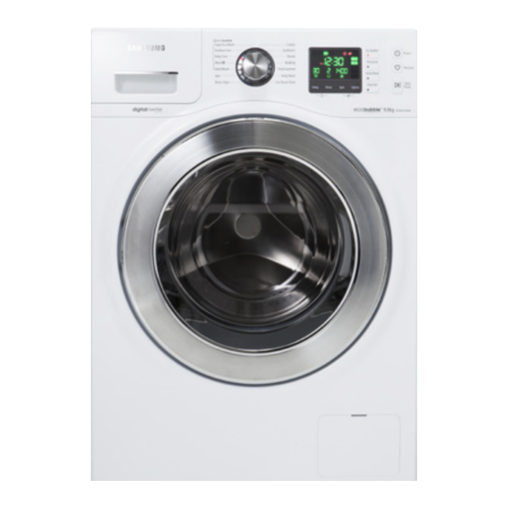
WASHING MACHINE
DRUM TYPE
Basic Model :
WF906***
(SEINE PROJECT)
Model Name :
WF8*F*E**
(F500E PROJECT)
Model Code :
WF80F5E5W4W/EF
(F500E PROJECT)
Manual
1. Safety Instructions
2.
3. Disassembly and Reassembly
4. Troubleshooting
5. PCB Diagram
6. Wiring Diagram
7. Reference
CONTENTS

Advertisement

Table of Contents
loading
Need help?

Need help?

Do you have a question about the WF906 Series and is the answer not in the manual?

Questions and answers

Subscribe to Our Youtube Channel

Summary of Contents for Samsung WF906 Series

  • Page 1 WASHING MACHINE DRUM TYPE Basic Model : WF906*** (SEINE PROJECT) Model Name : WF8*F*E** (F500E PROJECT) Model Code : WF80F5E5W4W/EF (F500E PROJECT) SERVICE Manual WASHING MACHINE (DRUM) CONTENTS 1. Safety Instructions 3. Disassembly and Reassembly 4. Troubleshooting 5. PCB Diagram 6.
  • Page 2: Table Of Contents

    CONTENTS 1. Safety instructions ..............1 1-1.
  • Page 3: Safety Instructions

    1. SAFETY INSTRUCTIONS 1-1. SAFETY INSTRUCTIONS FOR SERVICE ENGINEERS ► Make sure to observe the following instructions to operate the product correctly and safely and prevent possible accidents and hazards while servicing. ► Two types of safety symbols, Warning and Caution, are used in the safety instructions. Hazards or unsafe practices that may result in severe personal injury or death. WARNING Hazards or unsafe practices that may result in minor personal injury or property damage. CAUTION WARNING BEFORE SERVICING...
  • Page 4 WARNING WHILE SERVICING • Check if the power plug and outlet are damaged, flattened, cut or otherwise degraded. 4 If faulty, replace it immediately. Failing to do so may result in electric shock or fire. • Completely remove any dust or foreign material from the housing, wiring and connection parts. 4 This will prevent a risk of fire due to tracking or short circuiting. • When connecting wires, make sure to connect them using the relevant connectors and check that they are completely connected. 4 Do not use tape instead of the connectors, it may cause fire due to tracking. • Make sure to discharge the PBA power terminals before starting the service. 4 Failing to do so may result in a high voltage electric shock. • When replacing the heater, make sure to fasten the nut after ensuring that it is inserted into the bracket-heater. 4 If not inserted into the bracket-heater, it touches the drum and causes noise and electric leakage. WARNING AFTER SERVICING • Check the wiring. 4 Ensure that the wiring can not be damaged by any sharp edges or moving parts. • Check for any water leakage. 4 Perform a test run for the washing machine using the standard course and check whether there is any water leakage through the floor section or the pipes. • Do not allow consumers to repair or service any part of the washing machine themselves. 4 This may result in personal injury and shorten the product lifetime.
  • Page 5 CAUTION BEFORE SERVICING • Do not sprinkle water onto the washing machine directly when cleaning it. 4 This may result in electric shock or fire, and may shorten the product lifetime. • Do not place any containers with water on the washing machine. 4 If the water is spilled, it may result in electric shock or fire. This will also shorten the product lifetime. • Do not install the washing machine in a location exposed to snow or rain. 4 This may result in electric shock or fire, and shorten the product lifetime. • Do not press a control button using a sharp tool or object. 4 This may result in electric shock or damage to the product. CAUTION WHILE SERVICING • When wiring a harness, make sure to seal it completely so no liquid can enter. 4 Take care when disconnecting connectors, do not use excessive force as this may damage the connector. • Check to see if there is any residue that would imply liquid has entered the harnesses or electrical parts. 4 If any liquid has entered into a part, replace it or completely remove any remaining moisture from it. • If you need to place the washing machine on its back for servicing purposes, place a support(s) on the floor and lay it down carefully so its side is on the floor. 4 Do not lay it down on its front. This may result in the inside tub damaging parts. Safety Instructions _ 3...
  • Page 6 CAUTION AFTER SERVICING • Ensure that all components are reassembled correctly and are safe before connecting the appliance to the mains supplies. • Check the insulation resistance. 4 Disconnect the power cord from the power outlet and measure the insulation resistance between the power plug and the grounding wire of the washing machine. The value must be greater than 10MΩ when measured with a 500V DC Megger • Check whether the washing machine is level in relationship with the floor. Check whether it is installed firmly on the floor. 4 Vibrations can shorten the lifetime of the product. 4 _ Safety Instructions...
  • Page 7: Features And Specifications

    2-1. FEATURES ■ COMMON FEATURES Features Description Bubble Wash Technology • Bubble Wash technology activates the detergent solution from the start of the wash and generates bubbles through the Bubble Generator so that the detergent dissolves more quickly and the detergent bubbles generated at the start of the wash penetrate the fabric of the laundry faster and more effectively than a conventional wash guaranteeing a cleaner wash. In particular, the lower the water temperature is, the better the effect. In addition, since washing is performed after the detergent is completely dissolved in the water, there is no need to worry about any remaining detergent residue. • Using a Samsung washing machine, you can wash waterproof clothing without worrying about damage to material not previously washable. The outdoor care course of a Samsung washing machine provides an excellent wash performance and fabric care level by minimizing damage to the waterproof material. Most Efficient • This model offers more efficient energy use compared to standard A rated (Selected Model) machine with the special Bubble generator system and Samsung BLDC motor. Eco Bubble tech. High efficiency BLDC motor 15´ Quick Wash • No time to lose! Quick Wash will give you time to run out before it’s too late. Our Quick Wash program can be the solution to your busy life. Now you can wash your favorite clothes in 15 minutes!
  • Page 8 Features Description Diamond Drum • The washing performance has increased but potential damage to the washing has been minimized. (The size of the holes on the diamond drum has been reduced for minimizing damage to the washing.) - The embossed wall of the drum serves as a washboard, dramatically increasing the washing performance compared with existing drum washing machines, which use the power of the difference in elevation only. - The size of holes has been reduced drastically, maintaining the optimal wash performance while saving on water and electricity required for washing. - The structure of the holes on the diamond drum has been changed minimizing potential damage to the washing since it is difficult for strands to enter the holes. Conventional Fabric Diamond Drum Fabric Eco Drum Clean • Using Eco Drum Clean helps to keep your washing machine clean even without (Selected Model) any chemical detergent or bleach. Keep your drum cleansed and odorless with this specialized cleaning program. 6 _ Features and Specifications...
  • Page 9 Water Safety System • The Water Safety System allows for perfect leakage protection. The double safety (Selected Model) valve connects directly to the water tap. In the event of a leakage, the built-in sensor immediately detects the leak, within a few short seconds, automatically turning off both the water supply and the washing machine. - Inlet hose It is attached to the water supply hose and automatically cuts off the water supply if the hose is damaged. It also displays a warning indicator. - Leakage Sensor A water leakage sensor attached at the bottom of the washing machine to cut off the power automatically if a leakage occurs, to prevent the danger of a fire. Ceramic Heater • The ceramic heater in Samsung washing machines prevents metals in hard water (Selected Model) from being attach to the heater, which may cause a reduction in heater efficiency. This helps save energy, time and money. Energy Savings Over time, conventional heaters increase their power consumption an average of 5.8 percent, while ceramic heaters only become 1.8 percent less efficient. Time Savings After three years, conventional heaters take 7.5 percent longer to heat up, remove as is a duplicate, whereas ceramic only lose 2.5 percent of their ability to heat up. 10 Years Ceramic Enlarged...
  • Page 10: Specifications

    2-2. SPECIFICATIONS Model WF8*F*E**** WF7*F*E** Wash Type FRONT LOADING TYPE Dimension 850 X 600 X 550 Water Pressure 50-800 Weight 61kg 61kg Wash & Spin Capacity 220V / 150W WASHING 240V / 150W Power Consumption 220V / 2,000W WASHING and HEATING 240V /2,400W Spin Revolution 1,400 / 1,200 8 _ Features and Specifications...
  • Page 11: Comparing Specifications With Existing Models

    2-3. COMPARING SPECIFICATIONS WITH EXISTING MODELS (H) : Functions may be different depending on the model. Grade F500E SEINE WF806P4SA** WF906P4SA** WF806U4SA** WF906U4SA** Model Name WF8*F*E** WF7*F*E** WF806UHSA** WF906UHSA** WF802B2SA** WF902B2SA** Image Eco Bubble Wash Bubble wash Feature Diamond Drum Diamond Drum Smart Check Capacity 8Kg / 7Kg 9kg / 8kg Drum Volume 63ℓ...
  • Page 12: Options Specifications

    2-4. OPTIONS SPECIFICATIONS Item Code Remarks BOLT-SPANER DC60-40146A Default 1 (H : Cold only) or For specific models HOSE-WATER DC62-10289B only 2 (H : Cold and Hot) 1 (H : Cold only) or HOSE-WATER For specific models DC62-00079A (AQUA-STOP) only 2 (H : Cold and Hot) MANUAL-BOOK DC68-03234A WF80F5E5U4W/EF CAP-FIXER DC67-00307A Default HOSE-HANGER DC62-10278A Default GUIDE-LIQUID DC61-03510A Default Note • (H) is supplied for specific models only among those without water supply hoses. • You can purchase additional water supply and drain hoses from a service center. • For built-in models, the spanner, water supply and drain hoses are not supplied. Both the water supply and drain hoses are supplied during the installation.
  • Page 13: Disassembly And Reassembly

    3. DISASSEMBLY AND REASSEMBLY 3-1. TOOLS FOR DISASSEMBLY AND REASSEMBLY Tool Type Remarks Heater(1),Tub(12), Fixer screw(5), Motor(2), 10mm Balance(9) Shock Absorber (2 holes each in left/right), Box driver 13mm Damper(2), Damper(friction 2) 19mm Pulley(1) 10mm Replaced by box driver Double-ended 13mm spanner 19mm A Tool for protecting empty turning of bolt or abrasion from using box driver Vice pliers For disassembly of Spin drum Others Common tools for servicing (screwdriver, nipper, long nose pliers) Torque wrench The Tool for assembly of heater and Tub Disassembly and Reassembly _ 11...
  • Page 14: Standard Disassembly Drawings

    3-2. STANDARD DISASSEMBLY DRAWINGS ► This is a standard disassembly diagram and may differ from the actual product. Use this material as a reference when disassembling and reassembling the product. Part Figure Description 1. Remove the two screws holding the Top Cover at the back of the unit. 2. Remove the top-cover by lifting it up after pulling it back about 15mm. Assy Cover Top Water valve Noise filter 3. Now the Water(pressure) Sensor, Noise Filter, Water Valve and main PCB can be replaced. Sensor pressure 12 _ Disassembly and Reassembly...
  • Page 15 Part Figure Description 1. Remove the 2 screws holding the front operating panel. 2. Remove the screws at the top of the ASSY- PANEL CONTROL. Sub-pcb panel 3. Hold the ASSY-PANEL CONTROL while pulling it upwards and release the hook to remove it. 4. Disconnect the 3 terminals connected to the PCB by hand. 5. Release the hooks on both sides to remove the PCB for repair / replacement. Disassembly and Reassembly _ 13...
  • Page 16 Part Figure Description 1. Remove this screw. 2. Remove the Band-ring. Assy Housing- drawer 3. Separate the water supply valve wire. 4. Remove the screws holding the water supply valve in place. 14 _ Disassembly and Reassembly...
  • Page 17 Part Figure Description 1. Using the long nose pliers, pick up one of the rings on the Wire-Diaphragm, which connects the sprints and the wire ends. Then separate the Wire-Diaphragm from the Front-Frame and Disconnect the Diaphragm. Frame Front 2. Remove the two screws holding the FRAME-FRONT. 3. Remove the screws holding the bottom of the FRAME-FRONT. 4. Disconnect the terminal for the DOOR- LOCK switch. Disassembly and Reassembly _ 15...
  • Page 18 Part Figure Description Unfasten the 4 screws that hold the back cover in place. Remove the back cover by sliding it Cover-Back down. (When assembling, slide the back cover up.) 1. Remove the Cover back . 2. Separate the belt and then assembly it. 3. Check if the belt position is at the center of Belt the Pulley. Assembling the belt Place the belt around the Motor-Pulley (①) and then over the Pulley (②). 1. Separate the Wire Housing from the motor. 2. Remove the bolts holding the motor at the back of the washing machine. 3. Separate the motor. UNIVERSAL MOTOR Caution When installing the Belt around the Motor Pulley, the bottom of the belt must be located on the second tooth of the motor pulley. 16 _ Disassembly and Reassembly...
  • Page 19 Part Figure Description 1. Separate the Assy-Cover Top. 2. Separate the water supply valve wire. Water supply valve 3. Remove the screws holding the water supply valve in place. Disassembly and Reassembly _ 17...
  • Page 20 Part Figure Description Water valve Noise filter 1. Separate the Assy Top-Cover. Sensor pressure Water level sensor 2. Disconnect the wire between the PRESSURE HOSE and the water level sensor for repair / replacement. 3 . Push the clip of the water level sensor behind sensor to one side of the frame and pull it out to remove it. 18 _ Disassembly and Reassembly...
  • Page 21 Part Figure Description 1. Remove the 2 screws holding the Door Hinge and separate the door. Door Hinge 2. Remove the 11 screws holding the Holder Glass and separate the Holder Glass. 3. Remove the 4 screws holding the bracket hinge and replace the door-hinge. Disassembly and Reassembly _ 19...
  • Page 22 Part Figure Description 1. U se coins or pins in order to open the Filter Cover. 2. R emove the remaining water through the drainage hose. Place a bowl under the drainage hose, or the remaining water may flow out. 3. Separate the Drain Filter by turning it Drain pump counterclockwise. Since the remaining water may flow out, place a bowl underneath it when separating the filter. 4. Remove the 2 screws holding the drain pump. 5. Release the BAND RING (3EA) to remove the HOSE (3EA). 20 _ Disassembly and Reassembly...
  • Page 23 Part Figure Description 6. Push the PUMP inward and then remove the HOSE (3EA). 7. Disconnect the wire (4EA). Drain pump 8. Push the TUB inward slightly to remove the PUMP Pump wire harness is connected to main wire harness. 4 Check Points for Troubleshooting 1. Separate the Drain Filter and check if any alien substances are inside the pump (e.g. coins, buttons .., etc.) → Remove these if found. 2. Check if the wire driving the pump has come loose → Take the relevant countermeasure if necessary. 3. When water leaks, check the assembly status of the Clamp Hose, and Cap Drain → Take the relevant countermeasure if necessary. Turn the filter counterclockwise to remove the remaining water. Disassembly and Reassembly _ 21...
  • Page 24 Part Figure Description 1. Open the Door. Remove the Wire Diaphragm and remove it from The Front Frame. For easier disassembly, remove the spring from the lower part of the Diaphragm with a (-) screwdriver. Since the Diaphragm can be damaged when removing it. Use a Longnose plier and remove it slowly in one direction. Door-lock S/W 2. Remove the 2 screws. 3. Remove the screw holding the Door-Lock S/W. Remove the Door-Lock S/W. Remove the connection wire. (Only remove the connector once the connector is released, this can be done by pressing the catch.) 1. Disconnect two wire connectors. Leakage Sensor 2. Remove the six screws holding the bottom of the FRAME-FRONT. (OPTION) 3. Remove the 2 screws. 22 _ Disassembly and Reassembly...
  • Page 25 Part Figure Description 1. Separate the Back Cover. 2. Separate the Connection Housing (3). 3. Remove the wire vinyl. (1) 4. Separate Connection Housing. Heater 5. Remove then nut holding the heater in place and then separate out the heater. Use box Drivers (Socket size: 10mm) 6. Remove the Heater from the Tub. Caution Make sure to insert the Heater into the correct position of the bracket inside the Tub when reassembling it. Otherwise, there is a danger of a fire. Make sure to push the Tub inwards until the packing part comes into the Tub completely when reassembling. Fasten the holding nut with a force of 5Kgf/ cm2. If the nut is not fastened properly, there is a danger of water leaking. Disassembly and Reassembly _ 23...
  • Page 26 Part Figure Description 1. Remove the back cover and unfasten the screws that hold the main PCB in place Replacement of the 2. Remove the PCB cover inside. main PCB Remove the wire harness connector which is connected to the PCB. 3. Replace the main PCB. You cannot remove the PCB separately because urethane is used for water proofing. 4 Check Points for Troubleshooting 1. Check whether there is any error in applying the power. 2. Check the voltage between the DC 5V and GND terminals. 3. If an error occurs when there is no characteristic error in the electric harnesses, check these points: HE/HE1 error: The resistance of heater(for 1900W unit) is 27 Ω DE1 error: The resistance of door switch is 140 to 145 Ω HE/HE1 error: The resistance of thermostat is 0 Ω 4E error: The resistance of water valve is 4.4 kΩ Reassembly is in the reverse order of the removal. 24 _ Disassembly and Reassembly...
  • Page 27: Troubleshooting

    4. TROUBLESHOOTING 4-1. ERROR MODES ► This is a washer integrated error mode. For detailed information, refer to the general repair scripts. Drum Fully Error Type Causes Remarks Error automatic error For USA mode mode - The part of the hose where the water level sensor is located is damaged (punctured). - The hose is clogged with foreign material. - The hose is folded.
  • Page 28 Drum Fully Error Type Causes Remarks Error automatic error For USA mode mode - The pump motor impeller is damaged internally. - The wrong voltage (220 V → 110 V) is supplied to the parts. - Part fault - This occurs due to freezing in the winter season Drain Error - The drain hose is clogged. (Injection error, foreign material) - Clogged with foreign material - The water pump terminal is not connected: rubber band, bills, cotton, hair pins, coins - Check the consumer’s power conditions. : Make sure to check the operating voltage. Connect a tester to the internal power terminals during the Boil or Dry operations and observe the washing machine’s operation carefully. : Check the voltages. (An error occurs when under or over voltage is supplied.) : Check whether a plug receptacle is used.
  • Page 29 Drum Fully Error Type Causes Remarks Error automatic error For USA mode mode - This occurs when the temperature of the washing machine is more than 50 ˚C and no draining is If this error performed. occurs for (Reason: If hot water comes into contact with skin, it another may cause burns.) reason, it Cooling Error - This occurs when the water temperature, for a is due to a specific course, exceeds 50 ˚C. In that case, the washing heater water will be drained to the Reset level. sensor fault. Replace it. - This represents a thermal sensor error or any misuse of the unit. When the door - A switch contact error because of a deformation is not opened of the door hook (Before...
  • Page 30 Drum Fully Error Type Causes Remarks Error automatic error For USA mode mode - Heater engagement fault (out of place) - The air hose is out of place and water leakage occurs during the spin cycle. - The tube back near the bolt fixing part is broken. - Water leakage occurs at the front with foaming because of too much detergent - Water leakage occurs because the connecting hose to the detergent drawer is connected incorrectly. Water Leakage Error - The drain pump filter cover is engaged incorrectly. - Water leakage occurs at the drain hose. - The duct condensing holding screws are worn. - The nozzle-diaphragm is engaged in the opposite direction or the rubber packaging is omitted. - Water leakage occurs because the screws that hold the tub back and front in place are fastened incorrectly.
  • Page 31 Drum Fully Error Type Causes Remarks Error automatic error For USA mode mode - This occurs when too much foaming is detected. It is also displayed while foaming is removed. When the removal is finished, the normal cycle Foaming proceeds. “Sud” or “SUdS” is displayed when too SUdS Detected much foaming is detected and “End” is displayed when the removal of the foaming is finished. (This is one of the normal operations. It is an error for preventing non-sensing faults.) Troubleshooting _ 29...
  • Page 32: Corrective Actions For Each Error Code

    4-2. CORRECTIVE ACTIONS FOR EACH ERROR CODE 30 _ Troubleshooting...
  • Page 33 Troubleshooting _ 31...
  • Page 34 32 _ Troubleshooting...
  • Page 35 Troubleshooting _ 33...
  • Page 36 34 _ Troubleshooting...
  • Page 37: Pcb Diagram

    5. PCB DIAGRAM 5-1. MAIN PCB ► This Document can not be used without Samsung’s authorization. Location Part No. Function Description POWER SUPPLY RELAY Receive 230V AC to operate PBA HEATER RELAY Heater power output MOTOR CONTROL TERMINAL Motor signal output REACTOR TERMINAL Connect with the Reactor DRIVING SECTION TERMINAL Signal Output for door lock, water valve, drain pump and bubble pump. POWER SUPPLY AND DOOR CHECK TERMINAL Receive 230V AC to operate PBA and Door lock check SUB PBA CONNECTION TERMINAL Connect with SUB PBA CONTROLLER BOARD Control whole PBA and have Program Update terminal PCB Diagram _ 35...
  • Page 38: Circuit Diagrams Of Main Parts

    5-2. CIRCUIT DIAGRAMS OF MAIN PARTS ► This Document can not be used without Samsung’s authorization. ► CN1 1. Main Tx (Sub Rx) Signal 2. Main Rx (Sub Tx) Signal 3. Sub Reset Signal 4. 5V 5. GND 6. 15V ► CN2 7. N.C 8. N.C 1. Power Signal 2. Door lock/unlock Check Signal 9. Standby Signal 3. N.C 10. N.C ► Controller Board 1. 5V for Program Update...
  • Page 39: F500 Best

    5-3. F500 BEST ► This Document can not be used without Samsung’s authorization. Location Part No. Function Description CN2 COMMUNICATION TERMINAL (MAIN PBA) Connect with MAIN PCB BUZZER Make sound for key input, or program finish, etc. DSP1 GRAPHIC DISPLAY Display information about selected Operation Mode. CN1 PROGRAM UPDATE TERMINAL Terminal for program update PCB Diagram _ 37...
  • Page 40: Detailed Descriptions Of Contact Terminals (Sub Pcb)

    5-4. DETAILED DESCRIPTIONS OF CONTACT TERMINALS (SUB PCB) ► This Document can not be used without Samsung’s authorization. ► CN1 1. . 5V for Program Update 2. Reset signal for Program Update 3. signal for Program update 4. GND ► CN2 ► CN3 1. SUB Rx (Main Tx) Signal 1. Touch Sensor signal 2. SUB Tx (Main Rx) Signal 2. Touch Sensor Signal 3. RESET signal 3. Touch Sensor Signal 4. 5V 4. 15V for Touch Sensor 5. GND...
  • Page 41: Wiring Diagram

    6. WIRING DIAGRAM 6-1. WIRING DIAGRAM ► This Document can not be used without Samsungs authorization. ■ REFERENCE INFORMATION BLACK BLUE GREEN GRAY NATURAL ORANGE PINK SKYBLU SKYBLUE VIOLET WHITE YELLOW Wiring Diagram _ 39...
  • Page 42: Reference

    7. REFERENCE 7-1. F500 PROJECT NAME 40 _ Reference...
  • Page 43 GSPN (GLOBAL SERVICE PARTNER NETWORK) Area Web Site Europe, CIS, Mideast & Africa gspn1.samsungcsportal.com Asia gspn2.samsungcsportal.com North & Latin America gspn3.samsungcsportal.com China china.samsungportal.com © 2013 Samsung Electronics Co.,Ltd. All This Service Manual is a property of Samsung Electronics Co.,Ltd. rights reserved. Any unauthorized use of Manual can be punished under applicable Printed in Korea International and/or domestic law. Code No.: DC68-03234A...

Table of Contents

Save PDF