
Related Manuals for Raycus RFL-C6600S


Summary of Contents for Raycus RFL-C6600S
- Page 1 Continuous-Wave Fiber Laser User Guide RFL-C6600S Wuhan Raycus Fiber Laser Technologies Co., Ltd...
-
Page 2: Table Of Contents
Wuhan Raycus Fiber Laser Technologies Co., Ltd. User Guide of RFL-C6600S TABLE OF CONTENTS 1 Safety Information ........................3 1.1 Symbols Used in this User Guide ..................3 1.2 Laser Classification ......................3 1.3 Safety Labels ........................4 1.4 Optical Safety ........................5 1.5 Electrical Safety ........................ -
Page 3: Safety Information
Wuhan Raycus Fiber Laser Technologies Co., Ltd. User Guide of RFL- RFL-C6600S 1 Safety Information Thank you for choosingRaycus fiber laser. This User Guide provides important safety, operation, warranty and other information. Please read it carefully before you use this product. In order to ensure safe operation and optimal performance of the product, please follow the warnings, cautions, operating procedures and other instructions accordingly. -
Page 4: Safety Labels
The position of the safety labels on products varies depending on the model of the continuous-wave fiber laser, as shown in Figure 1: Figure 1 Safety Label Locations of RFL-C6600S These safety labels include warning labels, apertures through which laser radiation is emitted and labels of certification and identification, etc. -
Page 5: Optical Safety
There are no operator serviceable parts inside, and all maintenance must be performed in Raycus or by qualified Raycuspersonnel. Do not try to remove covers, or electrical shock may be caused, and warranty will be void. -
Page 6: Product Description
Please refer to the packing list accompanying the shipment to check actual items included. 2.3 Unpacking and Inspection Raycus CW fiber laser is shipped in a package designed to provide maximumprotection. Upon delivery, please inspect all packaging for evidence of mishandling or damage. If you find any evidence of mishandling, please save the damaged material and contact the shipping agent and Raycusimmediately. -
Page 7: Operation Environment
Wuhan Raycus Fiber Laser Technologies Co., Ltd. User Guide of RFL- RFL-C6600S Remove all the contents from the packing case. Take extra care when removing the unit out of the packing case to ensure that thefiber optic cable is not twisted,hauled or damaged. A comprehensive packing list is included with thesystem documentation. - Page 8 Do not look directly into the laser output. Be sure to wear protective glasses when operating the laser. Do not expose this product to high humidity(>95%) Do not let this product work below the ambient dew pointtemperature.(see Table 3) Table 3 The Constant Dew Point Table AMBIENT DEW POINT Maximum Relative humidity...
-
Page 9: Precautions For Use
Wuhan Raycus Fiber Laser Technologies Co., Ltd. User Guide of RFL- RFL-C6600S 2.5 Precautions for Use a) Before supplying the power to the device, make sure that the correct voltage of the AC power source is used. Failure to connect power source correctly will damage the device;... - Page 10 width Power Table 4 (Continued) Nominal Output Long-term power stability ± 1.5 Power Nominal Output Modulation Frequency 5000 Power Nominal Output Duty ratio Range Power Pulse width≥160μs Red Guide Laser Power QBH Optical index of output optical cable μm Fiber Core Diameter μm 50μm Fiber Core mm×mrad...
-
Page 11: Installation
Wuhan Raycus Fiber Laser Technologies Co., Ltd. User Guide of RFL- RFL-C6600S 3 Installation 3.1 Dimensions Figure 2 shows dimensions of RFL-C6600S. Figure 2 (a) Frontand Rear panel view(unit: mm) Figure2 (b) Top and Side view(unit: mm) -
Page 12: Output Head And Installation
3.2 Output Head and Installation The laser outputheadof RFL-C6600S is thestandard QBH interface. The specific appearance and dimensions are shown in Figure 3 above. Compared with other models, the size of the protective end cap of the fiber delivery cable of this model is lengthened. - Page 13 Figure 4, and then connect the water inlet filter module with the water inlet of the RFL-C6600S laser, as shown in Figure 5. Figure 5 The water inlet filtration module is connected to the watercooling system...
- Page 14 tightenning the nut cover). It is recommended that the cleaning frequency be no less than once a week. c) Cooling water requirements: 1) It is recommended to use purified water. 2) In order to prevent mould growing that may lead to pipe blockage, we recommend to add alcohol about 10% of the total volume.
-
Page 15: Installation Procedure
Wuhan Raycus Fiber Laser Technologies Co., Ltd. User Guide of RFL- RFL-C6600S 12) Radius of the bending of the armored pipe: off-work state (i.e. transportation and reservation): minimum radius of bending ≥ 20 cm; in-work state: minimum radius of bending ≥ 30 cm;... - Page 16 Insert the water pipes into the inlet and outlet; e) Check the output head and clean it if necessary. This procedure must be performed by personnel of Raycus or authorized by Raycus. Make sure the environment is clean, or the output cable may be contaminated.
-
Page 17: Using The Product
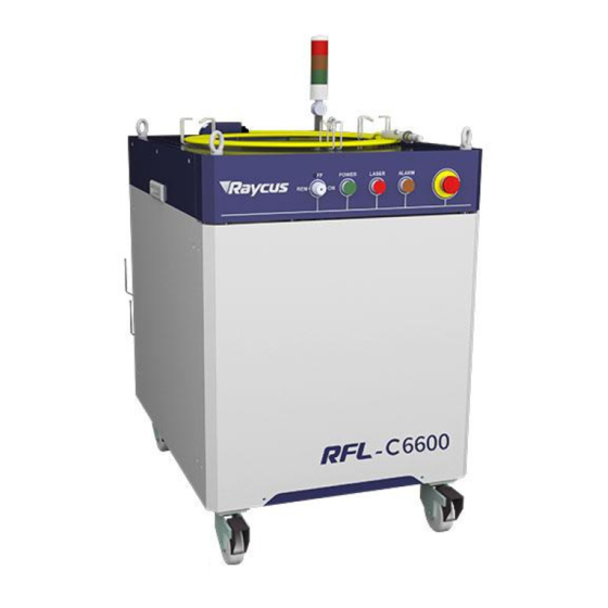
Please use the correct the latest PC software and the relevant manual. 4.1 Front Panel Figure 6 shows the front panel of RFL-C6600S: Figure 6 Front Panel of RFL-C6600S a) REM/OFF/ON: Key switch, the control systempower switch of the laser. Insert the key;... -
Page 18: Rear Panel
4.2 Rear Panel Figure shows the rear panel of RFL-C6600S: Figure 7 Rear Panel of RFL-C6600S a) AC INPUT: The socket for supply source input that can only be mated with the plug on the power cord we provided(See Table 4 product technical parameters for laser model and corresponding input voltage). -
Page 19: Power Connection
Wuhan Raycus Fiber Laser Technologies Co., Ltd. User Guide of RFL- RFL-C6600S d) WATER: Pipe connectors, the inlet and outlet for cooling water to flow in and return. (See Table 5 for the laser model and corresponding water pipe size for cooling system requirements) e) ETHERNET: Ethernet interface. -
Page 20: Interface Definitions
4.4 Interface Definitions 4.4.1 CTRL-INTERFACE Definitions The CTRL-INTERFACE(DB-25) is for laser control, the designation and definition is below: Figure 8 CTRL-INTERFACE Table 7 Definitions of 24 pin Ctrl Interface Drive Typical LineMar Name Type Level Curre Respons Description e Time ―EN954-1‖... - Page 21 Wuhan Raycus Fiber Laser Technologies Co., Ltd. User Guide of RFL- RFL-C6600S Analog Output 0-8 Analog VDC( Refer to factory Analog 0-8V Output Power AOUT 11mA 100µ s inspection report for Output Monitor details) Return for signals on pins Isolated...
- Page 22 Interlock interface must not be connected to active signal, otherwise it will cause interface damage and laser alarm. 4.4.2 TCP/IP Interface Configuration Thedefault IP address of this product is 192.168.0.10, only supporting UDP communication. The laser listens for connection on port is 8098, and the command must be sent in a single data string.
- Page 23 Wuhan Raycus Fiber Laser Technologies Co., Ltd. User Guide of RFL- RFL-C6600S f) Click the "OK" button to confirm the settings and exit. The IP address is different from the default gateway, see Figure 9. Figure 9 Steps of Ethernet Connection...
-
Page 24: Steps Of Installation
Figure 10 The main interface is displayed when the communication connection is normal 4.5 Steps of Installation a) Carefully takeout the laser from the box and move it to the installing position and then lock the casters; b) Remove the output cable protective cap and check the output lens for dust with strong light and clean it if necessary, then cover the output cable protective cap;... -
Page 25: Functions Of The Clientware
Turn on the key switch and start the laser. 4.7 Functions of the clientware The RFL-C6600S clientware communicates with the main control board through UDP when it is working. Through the background program running in the software and the human-computer interaction operation, the laser parameters are read and set and the control functions are realized. - Page 26 The control interface is the content displayed on the first page after opening the clientware, including the user's most commonly used status signal, laser parameter setting and laser control related functions. Control the main power: turn on or off the main power. After turning on or off the main power, the software will change the status of the main power.
- Page 27 Wuhan Raycus Fiber Laser Technologies Co., Ltd. User Guide of RFL- RFL-C6600S Control laser parameters: Optical output parameters include power, frequency, pulse width, and duty cycle.The communication between the software and the main control board requires only power, frequency, and pulsewidth.The duty cycle can be calculated from the pulse width and frequency, and the pulse width can also be calculated from the duty cycle and frequency.During the software operation, the frequency and duty cycle will be changed...
- Page 28 light output frequency, light output duty cycle, light pulse width, laser water flow, output optical cable water flow and other data. These status and data refresh time intervals should not exceed 300ms. Laser usage time display: including today's turn-on time, today's light-emitting time, cumulative turn-on time, and cumulative light-emitting time.
- Page 29 Raycus's limited time lock for integrators, and the lock time is for the integrator to end customers. Limited time lock. In the authorization interface, only Raycus‘...
- Page 30 Debug mode: On the basis of diagnostic mode, the parameter setting interface is added. Only Raycus debug engineers can enter the encryption mode. Diagnostic mode: When a fault occurs in the laser and the user needs to diagnose the fault remotely or learn more about the status of the laser, the user can enter the diagnostic mode.The...
- Page 31 Wuhan Raycus Fiber Laser Technologies Co., Ltd. User Guide of RFL- RFL-C6600S ACDC module and DCDC module on the basis of the observation mode. You need a password to enter the diagnostic mode. The initial password is 81338818 (password can be changed).
- Page 32 Figure 17 Alarm information interface of main control module Connect the network through the system parameter interface of the main control module: AP mode: the laser is a WiFi hotspot (the hotspot name and password can be configured). After the mobile phone is connected to the laser WiFi hotspot, you can use Ruike's mobile app to view the real-time status of the laser;...
- Page 33 Wuhan Raycus Fiber Laser Technologies Co., Ltd. User Guide of RFL- RFL-C6600S Figure 19 Slave control module status information interface Figure 20 Slave control module alarm information interface 4.7.10 ACDC module The ACDC module page contains the relevant status information of the ACDC module. It supports up to 4 ACDC modules.
- Page 34 Figure 21 ACDC module interface 4.7.11 DCDC module The DCDC module page contains the relevant status information of the DCDC module. It supports up to 12 DCDC modules. The refresh interval of the status information does not exceed 100ms. The data of the DCDC module needs to be forwarded by the main control module, so only the currently selected page is in the DCDC module.
-
Page 35: Control Modes
Wuhan Raycus Fiber Laser Technologies Co., Ltd. User Guide of RFL- RFL-C6600S 4.8 Control Modes The laser has two control modes, namely ON mode and REM mode. The user can select the mode to enter through the key ON the front panel.In ON mode, you can only set the power percentage, control the light output and light off.In REM mode, you can select AD mode, enable... - Page 36 4.8.2.1 Internal control in ON mode Ethernet Ethernet cable Shorten(pin 1-4,and pin INTERLOCK 2-3) Rear panel of laser Power cord AC input supply source Figure 23 Internal control wiring diagram in key switch "ON" and clientware mode Operation method: a) Spring the ―ESTOP‖ knob on the front panel; b) Key turning ―ON‖;...
- Page 37 Wuhan Raycus Fiber Laser Technologies Co., Ltd. User Guide of RFL- RFL-C6600S Ethernet Ethernet cable Shorten(pin 1-4,2-3) Rear panel INTERLOCK laser Pin 15,16 Modulation Power cord AC input supply source Figure 24 Wiring diagram of internal power control and external signal control in REM mode Operation method: a) Spring the ―ESTOP‖...
- Page 38 4.8.2.3 The internal/external modulation mode of the analog in REM mode Ethernet Ethernet cable Shorten(pin 1-4,2-3) Rear panel Pin 15,16(MOD) INTERLOCK The Control laser card Pin 12,14(0-10V analog) Power cord AC input supply source Figure 25 The power and laser are externally controlled wiring diagram in REM mode Operation method: a) Spring the ―ESTOP‖...
-
Page 39: Guide Laser Control
When the current program number of the laser is not 0, the laser runs in Program Mode.Please use the software of Raycus to edit the waveform, and select the program number of pre-run. The output waveform of laser is determined by the edited waveform. Under the... - Page 40 condition that all working conditions are met, the relation diagram of laser and programming waveform in programming mode is as follows: Programming waveforms Waveform switch: ONOFF/15, 16 pin Laser Figure 26 Relationship between laser and programming waveform in programming mode 4.10.2 The Programming Setup Interface (Waveform editing) Select "Show programming mode"...
- Page 41 Wuhan Raycus Fiber Laser Technologies Co., Ltd. User Guide of RFL- RFL-C6600S Figure 27 Selecting "Show programming mode" in "Mode Selection" Figure 28 Programming mode interface Figure 29 Interface diagram of programming setting 4.10.3 Checkingthe number of saved waveforms...
- Page 42 Figure 30 Checking the number of saved waveforms Click the "Refresh List" button, and the software will automatically list the number of saved waveforms,green indicates that the bar has a program, and white indicates that the bar is empty. 4.10.4 Checking the waveforms Figure 31 Check the waveforms...
- Page 43 Wuhan Raycus Fiber Laser Technologies Co., Ltd. User Guide of RFL- RFL-C6600S Select the waveform number, the program will automatically list the original waveform list. 4.10.5 Waveform Clearing Figure 32 Clearing waveform Click the program number to be cleared, click "clear", and then click "write laser", and the software will clear the waveform stored in the current laser.
- Page 44 Figure 33 Waveform editing Select the command under command type, write the command and click "Add". Figure 34 Selecting the command...
- Page 45 Wuhan Raycus Fiber Laser Technologies Co., Ltd. User Guide of RFL- RFL-C6600S After editing all the commands, click "Write laser". Figure 35 waveform writing success Click "Refresh List" again, and the new waveform number will turn green, indicating that writing is successful:...
- Page 46 Figure 37 Symbol for writing success 4.10.7 The Waveform Command Definition Table 15 The waveform convenient command word detailed Command code (1 Parameter 1 (2 bytes) Parameter 2 (4 bytes) Instructions byte) Program end command, STOP null null which must be the last command of each program.
-
Page 47: Laser Timing Diagram
Wuhan Raycus Fiber Laser Technologies Co., Ltd. User Guide of RFL- RFL-C6600S 4.11 Laser timing diagram ON模式——占空比=100% 连续时序图 Power >10s Ready ALARM >1ms 激光发射 ON/OFF 激光 Figure 38 Control sequence diagram in On mode 调制模式——内部脉冲占空比=100% Power >10s Ready ALARM >1ms 激光使能... -
Page 48: Modulation Signal Requirements
4.12 Modulation signal requirements The modulation frequency range of the RFL-C6600S laser is 1-5000Hz, and the minimum pulse width of the laser must be greater than or equal to 160us. Reference value of laser frequency and duty cycle setting is shown in Table 16. -
Page 49: Alarms And Solutions
When the laser establishes communication with the client software,all alarm states of the laser can be displayed on Raycusclientware,as shown in Figure 41(Download the Rsycus software and software manual, please log in to Raycus official website) Figure 41 The homepage of the clientware... - Page 50 Table 17 Instructions and solutionsfor alarms of laser Alarm name Alarm instructions and solutions Instruction: Low temperature/high temperature alarm of the laser. The sensor in the laser detects an abnormal temperature inside the laser. A high-temperature / low-temperature error occurs when the temperature at the monitoring point exceeds the set upper / lower limit.
-
Page 51: Warranty, Return And Maintenance
The warranties start on the date of shipment from Raycus for a period of time as set forth in the applicable purchase contracts or product specifications. Raycus has the right to choose to repair or... -
Page 52: Limitations Of Warranty
Only products with particular defects are under warranty. Raycus reserves the right to issue a credit note for any defective products produced in normal conditions. 6.2 Limitations of Warranty The warranty does not cover the maintenance or reimbursement of our productof which the...
Need help?
Do you have a question about the RFL-C6600S and is the answer not in the manual?
Questions and answers