
Subscribe to Our Youtube Channel
Related Manuals for Positron BRX-XLR


Summary of Contents for Positron BRX-XLR
- Page 1 BRX-XLR Broadband Reach eXtender – Extra Long Reach User Guide January 2018 BRX-XLR User Guide 180-0145-001-R02...
- Page 2 Product names, other than Positron's, mentioned herein may be trademarks and/or registered trademarks their respective owners. Disclaimer Notice Although Positron Access Solutions Corp. has made every effort to ensure the accuracy of the information contained herein, this document is subject to change. BRX-XLR User Guide...
- Page 3 Regulatory Compliance and Safety FCC Declaration of Conformance The BRX-XLR models comply with part 15 class A of the FCC Rules. Operation is subject to the following two conditions (1) This device may not cause harmful interference, and (2) this device must accept any interference received, including interference that may cause undesired operation.
- Page 4 Directive 2014/30/EU and 2014/35/EU. Français Par la présente Positron Access Solutions Corp. déclare que les modèles BRX-XLR sont conformes aux exigences essentielles et aux autres dispositions pertinentes selon les normes 2014/30/EU and 2014/35/EU.
- Page 5 The equipment must be connected to a protective ground in accordance with the instructions provided in this manual. Always ensure that BRX-XLR units are connected to a chassis ground path of 25 ohms or less to avoid damage to the equipment from lightning strikes and other electrical surges.
-
Page 6: Table Of Contents
Table of Contents General Description ......................6 BRX-XLR Main Advantages ..................... 6 Bandwidth Performance and Placement Flexibility ............6 Expected Bandwidth Improvement with BRX-XLR ............6 Typical Increases in Customer Serving Area ..............10 BRX-XLR Placement Flexibility ..................11 Optimum Placement......................12 BRX-XLR Calculator ...................... -
Page 7: General Description
A key factor in its performance is that the BRX-XLR significantly improves the signal to noise ratio seen by the CPE (in the downstream direction) and the DSLAM (in the upstream direction). - Page 8 For clarity, we are using the notion of a Bandwidth Improvement Ratio to illustrate the benefits of installing a BRX-XLR device on a copper pair. The ratio is calculated as the bandwidth using the BRX-XLR divided by the RAW bandwidth (i.e. without BRX-XLR). For instance, improving a pair from 5 Mbps to 10 Mbps would represent a Bandwidth Improvement Ratio of 2.0 (10 divided by 5).
- Page 9 Table 1: Downstream Performance Increase Examples (Typical Lines) Another way to view the benefits of the BRX-XLR is to look at the graph below which demonstrates the actual bandwidth performances (with and without BRX-XLR) as it relates to loop length using 26 AWG / 0.4mm copper gauge.
- Page 10 Figure 3: Bandwidth vs. Loop Length (feet) with and without BRX-XLR Figure 4: Bandwidth vs. Loop Length (meters) with and without BRX-XLR BRX-XLR User Guide 180-0145-001-R02...
-
Page 11: Typical Increases In Customer Serving Area
(i.e. with crosstalk) and with otherwise typical copper line conditions. Our field experience has shown that the BRX-XLR provides even better Improvement Ratios (i.e. Bandwidth Enhancement) when faced with “less than ideal” line conditions where the bandwidth is negatively impacted by bridge taps, influence from power lines and/or disturbances from other pairs or the use of other protocols in the same binder such as T1/E1, HDSL, and G.SHDSL. -
Page 12: Brx-Xlr Placement Flexibility
For instance, on a 26 AWG (0.4mm) loop of 12,500 feet / 3.8 km, placing the BRX-XLR anywhere between 6,000 feet / 1.8 km and 9,000 feet / 2.7 km away from the DSLAM will deliver 10 Mbps to the customer. -
Page 13: Optimum Placement
Figure 6: BRX-XLR Performance Improvement with Extended Placement Range (meters) 3.4 Optimum Placement Although the placement of the BRX-XLR is very flexible, the curves in section 3.3 above demonstrate that there is value in properly planning the placement to optimize performance. The following curve demonstrates the optimum placement of the BRX-XLR relative to total loop length. - Page 14 Having said that, service providers have a finite amount of locations per loop where they can install the BRX-XLR which will not always be at the optimum point. Positron Access has designed the BRX-XLR Calculator tool to assist in determining the optimum location for any given loop along with many suggested alternative placements with predicted performances.
-
Page 15: Brx-Xlr Calculator
3.5 BRX-XLR Calculator To view the impact related to the installation of a BRX-XLR unit on a given loop whether it is a 26 AWG (0.40mm), 24 AWG (0.51mm) or a 22 AWG (0.64mm) copper pair, a PC tool is available. You can request access to the Positron Customer Portal to download the BRX-XLR Calculator. - Page 16 Calculator. This may be caused by a number of factors. One of the most likely reason is that the Target SNR default value in the BRX-XLR Calculator (set to 6dB), is not the same as the one provisioned in the DSLAM. If that is the case, change the value in the Target SNR box to match the DSLAM setting.
-
Page 17: Technical Specifications
Regulatory Compliance UL/CSA, FCC part 15 Class A and CE Mark 2/10 μsec, 1 kA 8/20 μsec, 800A Tip/Ring Over-voltage 10/160 μsec, 400A Protection 10/700 μsec, 350A 10/560 μsec, 250A 10/1000 μsec, 200A Table 5: Technical specifications BRX-XLR User Guide 180-0145-001-R02... -
Page 18: Packaging Information And Port Density
The BRX-XLR-8 comes equipped with an IP67 enclosure that houses four (4) two-pair modules (as per image on the right below) for a total of eight (8) subscriber loops. Each BRX-XLR-M card has solid-state primary lightning protection for both pairs. In cases where more than 2 but less than 8 pairs are required, it is possible to order an empty enclosure (BRX-8C) and the required number of BRX-XLR-M 2-pair modules that are required. -
Page 19: Brx-Xlr-24 Packaging
(BRX-24CS) and the required number of BRX-XLR-M 2-pair modules that are required. Any empty slots in the BRX-24CS may be filled with BRX-BYPASS-TEST modules to allow for the pre-wiring of all the pairs in and out of the BRX-24CS enclosure. - Page 20 BRX-24S to amplify up to 48 pairs when you select the BRX-XLR-48-1SXPF version as per figure 16. Please refer to the BRX Product Selection Guide for more details. Figure 15: BRX-XLR-24-1SXPF. Figure 16: BRX-XLR-48-1SXPF BRX-XLR User Guide 180-0145-001-R02...
-
Page 21: Installation And Operating Guidelines
6 Installation and Operating Guidelines General Requirements for the Outside Plant (OSP) The BRX-XLR is designed to be installed and operated as per the same guidelines and standard operating procedures used for typical ADSL and ADSL2+ lines. Qualify/Condition the Line: the copper loops must be qualified and conditioned for ADSL/ADSL2/ADSL2+ installations according to standard operator guidelines ... -
Page 22: Pots / Voice Lines
(OSP). Equipment Connection Diagram The BRX-XLR is typically deployed adjacent to a splice point facilitating the selection of the xDSL pairs that require having the bandwidth increased or not. The following diagram illustrates how the BRX-XLR can be inserted between a DSLAM or MSAN and the subscribers it serves. - Page 23 The BRX-XLR needs to be powered from the POTS sealing current (-48V) originating from the DSLAM or the Central Office (CO). This is illustrated by Figure 18 below: Figure 18: Using Sealing Current to power the BRX-XLR BRX-XLR User Guide...
-
Page 24: Installation Procedure
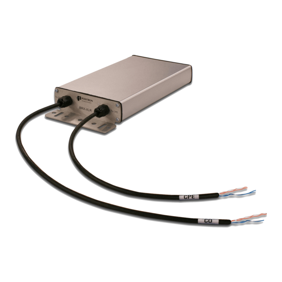
The BRX- BRX-XLR-2 standalone units are enclosed in an IP67/NEMA6 weather resistant enclosure. Please refer to the diagram below for a summary of the device. NOTE: the BRX-XLR -1 shares the same enclosure and installation instructions as the BRX-XLR-2 devices. -
Page 25: Overview Of The Brx-Xlr-8 Enclosure
Overview of the BRX-XLR-8 enclosure The BRX-XLR-8 supports up to 4 BRX-XLR-M modules enclosed in an IP67 / NEMA 6 weather resistant enclosure. Please refer to the diagram below for a summary of the device. All cables are Shielded, Gel- filled 24AWG/0.51mm cable... -
Page 26: Step-By-Step Installation Instructions
Please refer to section 8.1 for more details about bonding and grounding considerations. Step 3: when using an 8, 24 or 48 pair enclosure, insert the BRX-XLR-M modules in the slot matching the pair to amplify. The BRX module slots of the BRX-XLR-8 enclosure are... - Page 27 In this case, insert a metallic or plastic strap into the rectangular slot (0.2” by 0.8” / 5 mm by 20.3 mm) in the mounting flange at both ends of the BRX-XLR enclosure and secure around the pole as per the diagrams below.
- Page 28 When using the BRX-STRAND-K, use the supplied nuts and bolts to affix the strand mount bracket into the circular slots in the mounting flange at both ends of the 1-pair, 2-pair or 8-pair BRX-XLR enclosure as per the diagrams below. You can use any of the slots to adjust the strand mount bracket to clear any cables or devices already present.
-
Page 29: Splicing Pairs
Span between the strand and the BRX-XLR enclosure can vary from 3-9” (76 – 228 mm) Strand Diameter can range from ¼” (6.6 mm) to 3/8” (10 mm) Bracket Material: stamped from 5052 H34 Aluminum Mounting Bolt: Grade 2 steel and hot dip galvanized (as per ASTM A153) -
Page 30: How To Mitigate The Impact Of Disturbers
Actual data rates between the DSLAM and the user CPE may be lower depending on the conditions of the outside plant (OSP) and the location where the BRX-XLR unit is installed. Other signals such as T1, E1, ISDN, HDSL and G.SHDSL in the same cable binders will typically reduce the achievable bandwidth on ADSL2+/ADSL2 and ADSL. - Page 31 Figure 27: Grounding and Bonding next to Power Utility Pole Each BRX-XLR unit mounted on a pole or installed directly on a strand are to have an effective ground. It is highly recommended to bond all lead sheathed cable and the shields of plastic sheathed cable together and bond to the grounded bonding ribbon.
-
Page 32: Impulse Noise Protection
Impulse Noise Protection While the BRX-XLR is very effective at mitigating the impact of longer loops and the resulting higher signal attenuation, there are other factors that will negatively impact the performance of an xDSL loop. Let’s examine in this section how to mitigate the impact of noisy lines by leveraging the Impulse Noise Protection (INP) capabilities of the DSLAM and by providing proper grounding and bonding of the equipment in the copper Outside Plant (OSP). -
Page 33: Troubleshooting Guidelines
Verify that DSLAM and CPE pairs are not DSLAM and CPE are no longer able mistakenly swapped. Only the pair labelled to achieve synchronization DSLAM can be used to power the BRX-XLR device. Verify that there is POTS voltage on the DSLAM pair to power the BRX-XLR. - Page 34 DSLAM and without the BRX-XLR installed should be -40VDC to -60VDC - Voltage in ON-HOOK state on the pair from the DSLAM with the BRX-XLR installed should be - 38VDC to -58VDC - Voltage in the OFF-HOOK state on the pair from...
- Page 35 BRX-XLR. If you believe that the instability is the result of the installation of the BRX-XLR, please refer to the other problems covered in this table for the more likely source of the issue and the steps to remediate it.
- Page 36 DSLAM and the BRX-XLR. Using the telephone test set, verify that the loop current at the CPE pair of the BRX-XLR in the OFF-HOOK state is high enough (> 20mA) and that the voltage on the DSLAM BRX-XLR pair is about 20VDC.
- Page 37 - Standard Telephone Test set With the house disconnected at the NID and the BRX-XLR installed on the copper pair, verify if the audible hum noise is still present. If the noise disappears then the problem is with the house wiring.
- Page 38 If the measurements for the copper pair do not match the above guidelines, please follow the corporate procedure to rectify the situation and verify again if the problem is still present. Table 10: BRX-XLR Troubleshooting BRX-XLR User Guide 180-0145-001-R02...
-
Page 39: Warranty And Customer Service
10 Warranty and Customer Service Positron Access Solutions will replace or repair this product within the warranty period if it does not meet its published specifications or fails while in service. Warranty information can be found in your Positron Access customer web portal: http://www.positronaccess.com/Portal.php... -
Page 40: Ordering Information
BRX-XLR-2 BRX-XLR 2-pair module with solid state primary lightning protection enclosed in IP67 enclosure BRX-XLR-8 BRX-XLR 8-pair enclosure for up to 4 BRX-XLR-M modules with solid state primary lightning protection enclosed in IP67 enclosure BRX-XLR-24 BRX-XLR 24-pair enclosure for up to 12 BRX-XLR-M modules... -
Page 41: Annex A
Alternative ranges of such INP/delay can be useful but should be tested since there can be a wide variation of support between vendors. BRX-XLR User Guide 180-0145-001-R02... - Page 42 ADSL2plus equipment that they plan to use in order to determine more realistic achievable net data rates. Table 12: Maximum Downstream Attainable Rate, no Extended Framing Parameters Table 13: Maximum Downstream Attainable Rate with 16K Interleaving and BRX-XLR User Guide 180-0145-001-R02...
- Page 43 Extended Framing Parameters Table 14: Maximum Downstream Attainable Rate with 24K Interleaving and Extended Framing Parameters BRX-XLR User Guide 180-0145-001-R02...
-
Page 44: Annex B
Annex B Positron Access Solutions – Pair Validation Guidelines Test & Pass / Fail Criteria Results Circuit and Pair ID Power Influence - < 80 dBrnC Noise - < 20 dBrnC Tip to Ground, ≤ |1.0 VDC Tip to Ring: 0 VDC Tip to Ground: <... -
Page 45: Annex C
6.0 dB 6.0 dB Minimum SNR Margin 3.0 dB 3.0 dB SNR Margin Upshift 9.0 dB 9.0 dB SNR Margin Downshift 3.0 dB 3.0 dB Bit Swapping Enabled Enabled Table 17: Recommended ADSL2+ Test Set Profile BRX-XLR User Guide 180-0145-001-R02...
Need help?
Do you have a question about the BRX-XLR and is the answer not in the manual?
Questions and answers