
Subscribe to Our Youtube Channel
Related Manuals for Thytronic SME2-IS


Summary of Contents for Thytronic SME2-IS
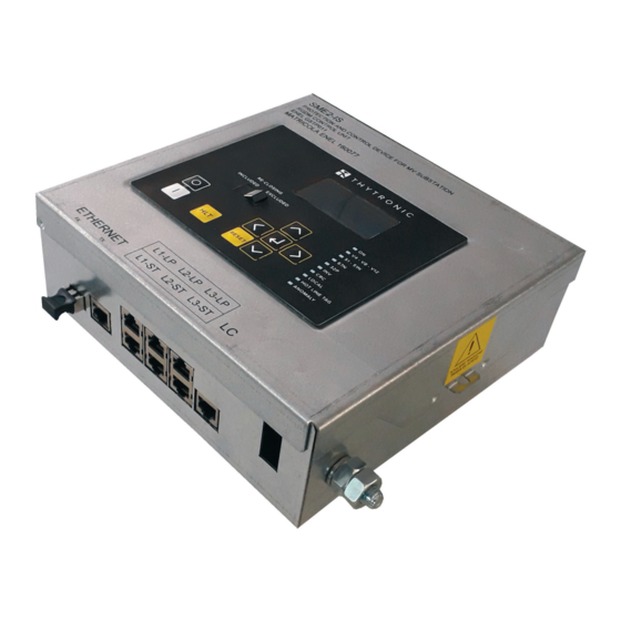
- Page 1 FAULT DETECTOR CONFORMING TO ENEL SPECIFICATION GSTP011 (PROTECTION AND CONTROL DEVICE FOR MV SUBSTATION – RGDM CONTROL UNIT) MANUAL SME2-IS - Manual - 06 - 2021...
-
Page 2: Table Of Contents
Overcurrent - 50/51 ....................................15 Residual overcurrent - 50N/51N .................................16 Ground directional overcurrent - 67N ................................16 ALB frequency (automatic load balancer) ..............................16 Second harmonic restraint - 2ndh-REST ..............................17 Averaged values ......................................17 THD monitoring ......................................17 Breaker diagnostics ......................................17 SME2-IS - Manual - 06 - 2021... - Page 3 Relays ..........................................61 Counters ..........................................61 Protection diagnostic status ..................................61 Selective block - BLOCKS ....................................62 Virtual inputs ........................................62 Virtual outputs ........................................62 Fault logging - SFR ......................................62 Event logging - SER ...................................... 63 Measurement logging ....................................63 SME2-IS - Manual - 06- 2021...
- Page 4 First protection threshold 50/51 - IEC extremely inverse time curves (type C, VIT) ................80 9.2 APPENDIX B - Insertion diagram ...................................81 9.3 APPENDIX C - SME2-IS panel dimensions ..............................82 9.4 APPENDIX D - Revisions ....................................83 9.5 APPENDIX E - CE Declaration of Conformity ...............................84...
-
Page 5: Preface
Contacts: THYTRONIC Technical Service www.thytronic.it Copyright All rights reserved; documents may not be reproduced without the permission of Thytronic, nor may the firmware and its related software be copied or modified. Warranty The product is covered by a one year warranty. -
Page 6: Ambient Conditions
IEC terminology indicating the polarity of the CT secondary (as an alternative to the ANSI dot symbol) Note 1 For the detailed description of the graphic interface and use of the Thyvisor software, refer to the respective chapter SME2-IS - Manual - 06 - 2021 INTRODUCTION... - Page 7 An intentional reset delay which can be set by the user. Man Machine Interface Software Firmware Thyvisor The parameter reading and setting software Log file A text file which logs the operations of a program (Thyvisor) Upgrade Firmware update EXtensible Markup Language INTRODUCTION SME2-IS - Manual - 06- 2021...
- Page 8 OR and NOR logical ports ≥1 EXOR logical port Resettable timer with tripping delay (tripping time tON) Non-resettable timer with tripping delay (tripping time tON) Non-resettable timer with reset delay (reset time tOFF) Symbols.ai SME2-IS - Manual - 06 - 2021 INTRODUCTION...
- Page 9 (reset time RESET OUTPUT RESET INPUT Minimum tripping time for output relays ( OUTPUT INPUT Latched operating mode of output relays and Latched LEDs OUTPUT INPUT Pulse operating mode of output relays OUTPUT Symbols1.ai INTRODUCTION SME2-IS - Manual - 06- 2021...
-
Page 10: General Information
Two Ethernet communications ports are available, of which one runs the IEC61850 protocol. To ensure full compatibility with any RTUs already on the secondary systems, the SME2-IS device is equipped with a dual interface to dialogue with both the UP (DX1215) and future communications equipment. -
Page 11: Technical Characteristics
EN 60255-22-3, IEC 60255-22-3 EN 61000-4-3 IEC 61000-4-3 Radiated electromagnetic fields • 80...2700 MHz AM 80% 10 V/m • 900 MHz pulse modulated 10 V/m Reference standards EN 60255-22-4 IEC 60255-22-4 EN 61000-4-4 IEC 61000-4-4 TECHNICAL CHARACTERISTICS SME2-IS - Manual - 06- 2021... -
Page 12: Issue
Directional fault detector and measuring relay RGDM ST Prescriptions and test methods ENEL GSTP011 Ver. 01 (26/07/2019) ENEL GSTP012 Ver. 01 (26/07/2019) ENEL GSTP013 Ver. 01 (26/07/2019) ENEL GSTP901 Ver. 01 (06/12/2018) Smart Termination ENEL DJ5400 - ENEL GSCT0051 SME2-IS - Manual - 06 - 2021 TECHNICAL CHARACTERISTICS... -
Page 13: Certifications
• Positive active power (xx...xx kW primary) 12-20 mA • Negative active power (xx...xx kW primary) 4-12 mA • Positive reactive power (xx...xx kVAR primari) 12-20 mA • Negative reactive power (xx...xx kVAR primari) 4-12 mA TECHNICAL CHARACTERISTICS SME2-IS - Manual - 06- 2021... -
Page 14: Mmi
‡ Cyclical input sequence Cyclical sequence of phase currents (I-Sequence) IL1-IL2-IL3,..Cyclical sequence of phase voltages (V-Sequence) UL1-UL2-UL3, UL1-UL3-UL2..‡ Polarity Polarity I-L1 (I-L1 POL) NORMAL/INVERTED Polarity I-L2 (I-L2 POL) NORMAL/INVERTED SME2-IS - Manual - 06 - 2021 TECHNICAL CHARACTERISTICS... -
Page 15: Timers Associated With The Logical Inputs
• Second harmonic restraint (I>>> ON/OFF 2ndh-REST Time-independent • Third time-independent threshold 51 (I>>> 0.02...3.00 I • Characteristic angle (ThetaP>>> 0...359 ° • Tripping time (t>>> 0.05...10.00 s • Tripping sector (Beta I >>>) 0...90 ° TECHNICAL CHARACTERISTICS SME2-IS - Manual - 06- 2021... -
Page 16: Residual Overcurrent - 50N/51N
Reset delay tULS>RES 0.00 ...9.99 s (step 0.01 s) 10.0 .. 100.0 s (step 0.1 s) Tripping time tULS> 0.05 ...9.99 s (step 0.01 s) 10.0 .. 99.9 s (step 0.1 s) SME2-IS - Manual - 06 - 2021 TECHNICAL CHARACTERISTICS... -
Page 17: Second Harmonic Restraint - 2Ndh-Rest
Interrupted current sum threshold (SumI) 0...5000 I Opening time for calculation ∑I t (t 0.05...1.00 s break Interrupted I^2t sum threshold (SumI^2t) 0...5000 I Maximum admitted opening time (t >) 0.05...1.00 s break TECHNICAL CHARACTERISTICS SME2-IS - Manual - 06- 2021... -
Page 18: Automation Functions
• No voltage threshold V2 (V < 0.05...0.60 E SYNC • Minimum no voltage time V1 (t < 0.00...10.0 s SYNC • Minimum no voltage time V2 (t < 0.00...10.0 s SYNC SME2-IS - Manual - 06 - 2021 TECHNICAL CHARACTERISTICS... -
Page 19: Monitoring And Control Functions
Phase shift of I relative to U Alpha3 Phase shift of U relative to I PhiE Sequences Direct sequence voltage Reverse sequence voltage Note 1 This function requires a license, contact Thytronic to purchase it TECHNICAL CHARACTERISTICS SME2-IS - Manual - 06- 2021... - Page 20 Average power measures Fixed mean active power Fixed mean reactive power Mobile mean active power Mobile mean reactive power Maximum active power Maximum reactive power Minimum active power Minimum reactive power SME2-IS - Manual - 06 - 2021 TECHNICAL CHARACTERISTICS...
-
Page 21: Fault Recording
• Phase-to-phase voltage U ‡ GD measurement recording Data logged: • Valid measurement counter ValMemGD • Time reference Date and time • Total active power • Total reactive power • Phase-to-phase voltage U TECHNICAL CHARACTERISTICS SME2-IS - Manual - 06- 2021... -
Page 22: Functional Characteristics
FUNCTIONAL CHARACTERISTICS FUNCTIONAL CHARACTERISTICS HARDWARE The following schematic gives a block diagram of the relay. SME2-IS - Manual - 06 - 2021 FUNCTIONAL CHARACTERISTICS... -
Page 23: Software
• REE and PAR containing data recorded to non-volatile memory. Self test (application) This function cyclically monitors the operation of the main hardware and software functions without significantly slowing down the processing cycle. FUNCTIONAL CHARACTERISTICS SME2-IS - Manual - 06- 2021... -
Page 24: Configuration And Calibration
The procedure calibrates the reference voltage U (see table above). With the device powered on and voltage U available, launch the Start Calibration command in the menu “Commands \ UL4 Calibration”. SME2-IS - Manual - 06 - 2021 FUNCTIONAL CHARACTERISTICS... -
Page 25: Inputs/Outputs
3 line voltage inputs 3 phase current inputs 3 line voltage inputs 3 phase current inputs Capacitive voltage dividers * Used for the RVL function and as V for function 25 Synch FUNCTIONAL CHARACTERISTICS SME2-IS - Manual - 06- 2021... -
Page 26: Measured Signal Processing
• the phase currents I ACQUISITION Active/passive sensors ≈ IL1. a i • the phase voltages U ACQUISITION Active/passive sensors ≈ SME2-IS - Manual - 06 - 2021 FUNCTIONAL CHARACTERISTICS... - Page 27 , the active power ±P and the reactive power ±Q, acquired every second, are calculated over a period t which can be set from 1 to 60 minutes and updated at the end of the period. FUNCTIONAL CHARACTERISTICS SME2-IS - Manual - 06- 2021...
- Page 28 L 2 MIN Average over period ∑ L x MIN L x n L 3 MIN R OL ±P ∑ ±P ±P Reset ±P R OL ±Q ∑ ±Q ±Q ±Q Min-Demand.ai SME2-IS - Manual - 06 - 2021 FUNCTIONAL CHARACTERISTICS...
-
Page 29: Measurement Conventions
For a set of three current phasors rotating counterclockwise, one conventionally assumes a direct cycle if the three phases follow the sequence L1, L2, L3, and an inverse cycle when the sequence is L1, L3, L2. Positive cyclic direction triple Negative cyclic direction triple fasori1.ai FUNCTIONAL CHARACTERISTICS SME2-IS - Manual - 06- 2021... -
Page 30: Led Signals
Hot Line Tag Communications interfaces The SME2-IS detector has the following interfaces: • One Ethernet 100 BaseT port for local connections (ThyVisor) • One Ethernet 100 BaseT port for connection to the field bus with the IEC61850 protocol and a fibre optical connection. -
Page 31: Protection Functions
(phase-to-phase) This must be set to the grid's nominal voltage. • Nominal phase-to-phase voltage of the relay U The SME2-IS detector automatically calculates the nominal secondary voltage U on the basis of the nominal primary voltage. • Measurement read mode (display format) -
Page 32: Voltage Present - Rvl
0.250 s ≥ U<TR-L 27-59 LOGIC State U< & Trip U< U< ≤ 0.500 s & Functional diagram for the threshodl of the voltage present/absent function — Overcurrent - 50/51 Foreword SME2-IS - Manual - 06 - 2021 FUNCTIONAL CHARACTERISTICS... - Page 33 Note 1 For input values greater than 20 times the threshold, the tripping time is limited to the value corresponding to 20 times the threshold Note 2 If the threshold is disabled (Enable = OFF) the trip command is not available but it still contributes to the internal logic FUNCTIONAL CHARACTERISTICS SME2-IS - Manual - 06- 2021...
-
Page 34: Residual Overvoltage - 51N
Timers for the rst residual overcurrent protection threshold - 51N Note 1 If the threshold is disabled (Enable = OFF) the trip command is not available but it still contributes to the internal logic SME2-IS - Manual - 06 - 2021 FUNCTIONAL CHARACTERISTICS... -
Page 35: Ground Directional Overcurrent - 67N
Note 2 The residual current IE is the vector sum of the three phase currents. Note 3 If the threshold is disabled (Enable = OFF) the trip command is not available but it still contributes to the internal logic FUNCTIONAL CHARACTERISTICS SME2-IS - Manual - 06- 2021... - Page 36 >>, I >>>, I >>>>) (β , β , β , β E> E>> E>>> E>>>> Φ ορ Φ Non-actuation sector SME2-IS Vectorial diagram of the directional ground function - 67N SME2-IS - Manual - 06 - 2021 FUNCTIONAL CHARACTERISTICS...
-
Page 37: Directional Detection Of Intermittent Ground Arcs
- a nul signal (=0) when the reset (R) is present 67.S4 (drop-out delay) 0.005 s 1.5 s ≥ (drop-out delay) IED> 0.005 s ≥ IED>> ≥ 0.1 s Functional diagram for the intermittent ground arcing detection function IED>>>> (67N.S4) FUNCTIONAL CHARACTERISTICS SME2-IS - Manual - 06- 2021... -
Page 38: Maximum Directional Active Power - 32P
Tripping characteristic of the threshold P> of the Directional active overpower function (32P) The function has an adjustable tripping threshold (P>) which can be delayed (t >) and has a time-in- dependent characteristic. SME2-IS - Manual - 06 - 2021 FUNCTIONAL CHARACTERISTICS... - Page 39 General functional diagram of the Directional active overpower function (32P) Note 1 If the threshold is disabled (P> Enable = OFF) the trip command is not available but it still contributes to the internal logic FUNCTIONAL CHARACTERISTICS SME2-IS - Manual - 06- 2021...
-
Page 40: Monitoring And Control Functions
• Number of semi-periods for calculating the third scale df/dt • Number of averages for calculating the first scale df/dt • Number of averages for calculating the second scale df/dt • Number of averages for calculating the third scale df/dt SME2-IS - Manual - 06 - 2021 FUNCTIONAL CHARACTERISTICS... - Page 41 EAC logic FUNCTIONAL CHARACTERISTICS SME2-IS - Manual - 06- 2021...
-
Page 42: Second Harmonic Restraint - 2Ndh-Rest
51.S2 and/or 51.S3 remain active, the second har- monic restraint block is disabled to enable it to trip. Functional diagram of the second harmonic restraint (2NDH/REST) The function can be enabled or disabled (default). SME2-IS - Manual - 06 - 2021 FUNCTIONAL CHARACTERISTICS... -
Page 43: Interface Methods
The open/close commands and the automatic reclosing function are handled by UP itself, which is connected directly to the DY 800. Communications between the SME2-IS and the substation router employ the IEC 61850 protocol and enable the use of the BLIND function. - Page 44 When a fault occurs, the SME2-IS transmits the information to the router/UP, which starts the auto- mation function. The automations on the router/UP send a series of IEC 61850 messages to the SME2-IS, to handle the operation of the DY 800 and run the reclosing cycle if necessary.
-
Page 45: Automatic Reclosing (79)
CB State CB CLOSED CB OPEN CB CLOSED CB OPEN CB CLOSED Neutralisation timer Rapid reclosing followed by fault and subsequent successful slow reclosing FUNCTIONAL CHARACTERISTICS SME2-IS - Manual - 06- 2021... - Page 46 From that time on, every new fault detected will be part of a new reclosing cycle. Neutralisation timer Discrimination timer Failed reclosing Rapid reclosing followed by fault and subsequent slow and memorized reclosings SME2-IS - Manual - 06 - 2021 FUNCTIONAL CHARACTERISTICS...
-
Page 47: Hot Line Tag Function
When the device is in local mode, this function may only be enabled/disabled using a dedicated physical button (independent of the physical reclosable function button) on the device's front panel, while in remote mode this function can be enabled/disabled via software or with a dedicated DNP3 command. FUNCTIONAL CHARACTERISTICS SME2-IS - Manual - 06- 2021... -
Page 48: Synchrocheck - 25
Synchronous grids For synchronous grids the final relay is commanded (synchronisation ok) when the following con- ditions obtain: • The activation signal is active, • the blocking input signal is inactive, SME2-IS - Manual - 06 - 2021 FUNCTIONAL CHARACTERISTICS... - Page 49 You can set the synchronisation attempt timeout (timeout ) in the menu Set \ Synchro -SYNC check - 25 \ Common configurations; if the conditions are not satisfied within this time, the se- quence is suspended. FUNCTIONAL CHARACTERISTICS SME2-IS - Manual - 06- 2021...
- Page 50 (PhiV1V2), available in the menu Read \ Measure- ments \ Synchrocheck, into the parameter Phase correction V1-V2 in the menu Set \ Calibra- tion Note 1 The Calibration menu is only available to Level 1 users SME2-IS - Manual - 06 - 2021 FUNCTIONAL CHARACTERISTICS...
- Page 51 “1” with breaker closed Binary input INx timeout- SYNC timeout- SYNC Reclosing sequence started by internal command (MMI or interface) Reclosing RESET Functional diagram of the synchronisation check function (25) for asynchronous grids FUNCTIONAL CHARACTERISTICS SME2-IS - Manual - 06- 2021...
- Page 52 “1” with breaker closed Binary input INx timeout- SYNC timeout- SYNC Reclosing sequence started by internal command (MMI or interface) Reclosing RESET Functional diagram of the synchronisation check function (25) for synchronous grids SME2-IS - Manual - 06 - 2021 FUNCTIONAL CHARACTERISTICS...
-
Page 53: Automatic Faulty Branch Selection Function
— Automatic faulty branch selection function The SME2-IS can be enabled or disabled to automatically select the faulty branch; if enabled, the device has the functions required to automatically select the faulty branch in: • FSL (logical selectivity function) • FRT (voltage relaunch function) which are mutually exclusive. - Page 54 3 minutes consecutively. Tripping delay Tr> Tatt 51A/67A Tripping delay ≥ + AP trip 51/67 command Tatt & BLIND held Blind Tatt+Tadd Selective block function - FSL tripping logic SME2-IS - Manual - 06 - 2021 FUNCTIONAL CHARACTERISTICS...
-
Page 55: Gd Management Function
The interface with the producer is provided by the router/up located in the substation, using the following connection scheme: Distributor User DG Position PG start System disconnection Extended function threshold set 8:1 Generation remote disconnection DI Position FUNCTIONAL CHARACTERISTICS SME2-IS - Manual - 06- 2021... -
Page 56: Virtual I/O
All parameters are available in the menu Set \ Virtual Inputs \ Settings. Mancata apertura interruttore 74TCS Monitoraggio del circuito di apertura dell’interruttore Richiusura automatica per fotovoltaico (opzionale) Note 1 Given the numerous possible applications, refer to the application notes for detailed information SME2-IS - Manual - 06 - 2021 FUNCTIONAL CHARACTERISTICS... - Page 57 Inversion Local Block All FUNCTIONAL CHARACTERISTICS SME2-IS - Manual - 06- 2021...
- Page 58 IE>>TR IED>TR IED>>TR IED>>>TR IED>>>>TR TEST_TRIP SME2-IS - Manual - 06 - 2021 FUNCTIONAL CHARACTERISTICS...
-
Page 59: Measurements, Logical States And Counters
23IST 31IST 10 s mean active power 10 s mean reactive power 10 s mean THD of current I THD-I L3IST 10 s mean THD of U THD-U L3IST MEASUREMENTS, LOGICAL STATES AND COUNTERS SME2-IS - Manual - 06- 2021... -
Page 60: Protection Status
• Interrupted current sum L3 xx In • Interrupted current sum I2t L1 xx In • Interrupted current sum I2t L2 • Interrupted current sum I2t L3 xx In SME2-IS - Manual - 06 - 2021 MEASUREMENTS, LOGICAL STATES AND COUNTERS... -
Page 61: Input Function Statuses
‡ Protection diagnostic status All hardware and software functions of Thytronic protection devices are continuously checked, all any faults are reported on the display, via the communications interfaces, LEDs and the output relays. Detailed diagnostics are divided into two levels: •... -
Page 62: Selective Block - Blocks
• Switching (OFF-ON) of an output relay associated with the tripping of a control or protection function Note 1 A relay may only be assigned to the self-diagnostics function by a level 1 user SME2-IS - Manual - 06 - 2021 MEASUREMENTS, LOGICAL STATES AND COUNTERS... -
Page 63: Event Logging - Ser
Note 5 The counter is incremented at each event; it can be reset using Thyvisor Nota 6 The digital fault recorder function requires a license - contact Thytronic to license it. Note 4 The data is saved to non volatile memory and is kept even when auxiliary power is absent... - Page 64 • Maximum percentage ratio of phase current second harmonic/fundamental component I -2nd Digital channel settings (Digital 1...12): • Input status UD, RVS, Anin, caX89, ccX89 (IN1...IN6) • Output status K1...K5 SME2-IS - Manual - 06 - 2021 MEASUREMENTS, LOGICAL STATES AND COUNTERS...
-
Page 65: Cyber Security
6 CYBER SECURITY 6 CYBER SECURITY — Preface The cyber security functions implemented by the SME2-IS mitigate cyber threats, by providing: • Protected communications between the SME2-IS and the mapped tool viaSSH (Secure SHell) • Password based user authentication • Management of authorisations for Role Based Access Control (RBAC) •... -
Page 66: Network Communication Security
The NTP, PTP synchronisation protocols are not normally encrypted. — Cybersecurity application scheme The configuration of the SME2-IS and monitoring functions pose problems relating to the security and privacy of the data traffic exchanged between the equipment and the remote control centre. -
Page 67: Installation
• secure the SME-I panel by fitting the four included M5 screws to the panel, after drilling it with the template given in the assembly drawings. 150mm Ø 5.5 mm Ø 5.5 mm Ø 5.5 mm Ø 5.5 mm Assembly INSTALLATION SME2-IS - Manual - 06- 2021... -
Page 68: Electrical Connections
Example hookup diagrams are given in an annex to this manual. The equipment must be installed and commissioned by a quali ed technician. Thytronic is not liable for any consequences of improper use. Terminal block hookup Screw terminals are provided inside the device for the MB, MI and MU connections, as follows: •... - Page 69 The communications ports are equipped with an RJ45 connector for local communications, and an LC (fibre optic) connector for the field bus. Ethernet 100 BaseT port for local comms (ThyVisor) Ethernet 100 BaseT port for eld bus connection (IEC61850) serial-sch.ai INSTALLATION SME2-IS - Manual - 06- 2021...
-
Page 70: Calibration And Start-Up
Thytronic protection relays using XML files. Installing ThyVisor The ThyVisor software is provided free of charge by Thytronic; the most recent version can be down- loaded from www.thytronic.it... -
Page 71: Reading Variables (Read)
• Press the button Enter for few seconds; new message appears: “Confirm settings?” • Answer to the message ENTER: YES to confirm or RESET: NO to abort The end of the two LEDs blinking points out the end of procedure. CALIBRATION AND START-UP SME2-IS - Manual - 06- 2021... -
Page 72: Test
Example: to open: appear the message: “OPEN CB? ENTER:YES RESET NO” • Press the button • Answer to the question ENTER: YES to confirm opening or RESET: NO to abort. SME2-IS - Manual - 06 - 2021 CALIBRATION AND START-UP... -
Page 73: Enabling / Locking The Keyboard - Password
• Disabled The operating modes can only be set via ThyVisor in a level 1 session: • Connect the PC's port to the SME2-IS fault detector's local port (RJ45) • Launch ThyVisor (use the most recent version, available on the website). - Page 74 The device's serial number must be entered to prevent IP address con icts with other devices on the Ethernet network The command Set Default Calibration sets the password to the default value = 0000. SME2-IS - Manual - 06 - 2021 CALIBRATION AND START-UP...
-
Page 75: Maintenance
CALIBRATION AND START-UP SME2-IS - Manual - 06- 2021... -
Page 76: Appendix
30 In and 10 IEn respectively Note 3 when the threshold regulation exceeds 20 times the threshold, the tripping time is limited to the value corresponding to 20 times the threshold SME2-IS - Manual - 06 - 2021 APPENDIX... -
Page 77: First Protection Threshold 50/51 - Iec Inverse Time Curves (Type A, Nit)
60 s 10 s 0.5 s 0.2 s 0.1 s 0.02 s Lorem ipsum 0.01 I /I>inv 7 8 9 10 Note: the set actuation time refers to a ratio I/I> = 700 F_51-IECA-Char.ai APPENDIX SME2-IS - Manual - 06- 2021... -
Page 78: First Protection Threshold 50/51 - Iec Very Inverse Time Curves (Type B, Vit)
10 s 0.5 s 0.1 s 0.2 s 0.02 s Lorem ipsum I /I>inv 0.01 7 8 9 10 Note: the set actuation time refers to a ratio I/I> = 14.5 F_51-IECB-Char.ai SME2-IS - Manual - 06 - 2021 APPENDIX... -
Page 79: First Protection Threshold 50/51 - Iec Long Inverse Time Curves (Type Lit)
60 s 10 s 0.5 s 0.2 s 0.1 s 0.02 s I /I>inv 0.01 7 8 9 10 Note: the set tripping time refers to a ratio II /I = 121 > F_51-IECB-LIT-Char.ai APPENDIX SME2-IS - Manual - 06- 2021... -
Page 80: First Protection Threshold 50/51 - Iec Extremely Inverse Time Curves (Type C, Vit)
60 s 10 s 0.02 s 0.1 s 0.2 s 0.5 s I /I >inv 0.01 7 8 9 10 Note: the set actuation time refers to a ratio /I> F_51-IECC-Char.ai SME2-IS - Manual - 06 - 2021 APPENDIX... -
Page 81: Appendix B - Insertion Diagram
TC CAX AnIn Capacitive voltage divider + 24 VDC for voltage present lamps ETHERNET FX + 24 VDC - 24 VDC to Router - 24 VDC Actuator (OdM) ETHERNET TX MU TERMINAL BLOCK APPENDIX SME2-IS - Manual - 06- 2021... -
Page 82: Appendix C - Sme2-Is Panel Dimensions
APPENDIX C - SME2-IS panel dimensions ANTI-TAMPER SME2-IS - Manual - 06 - 2021 APPENDIX... -
Page 83: Appendix D - Revisions
APPENDIX D - Revisions Version Version Configuration Firmware Firmware Documentation Date Description software APPENDIX SME2-IS - Manual - 06- 2021... -
Page 84: Appendix E - Ce Declaration Of Conformity
Piazza Mistral 7 - 20139 MILAN, ITALY The undersigned manufacturer herewith declares that the product SME2-IS - Directional fault detector and measuring relay is in conformity with the previsions of the following EC directives (including all applicable amendments) when installed in accordance with the installation instructions: Reference n°...
Need help?
Do you have a question about the SME2-IS and is the answer not in the manual?
Questions and answers