
Subscribe to Our Youtube Channel
Related Manuals for Thytronic SME70-C


Summary of Contents for Thytronic SME70-C
- Page 1 SME70 SME70-C SME70-M DIRECTIONAL EARTH FAULT, SHORT-CIRCUIT MANUAL AND VOLTAGE ELEMENTS SME70 27V1 59V2 SME70 27V1 59V2 SME70 27V1 59V2 SME70, SME70-C, SME70-M-Manual-04-2020...
-
Page 2: Warranty
All right reserved; It is forbidden to copy, modify or store material (document and sw) protected by copyright without Thytronic consent. — Warranty Thytronic warrants devices against defects in materials and workmanship under normal use for a period of ONE (1) YEAR from the date of retail purchase by the original end-user purchaser (“War- ranty Period”). -
Page 3: General Info
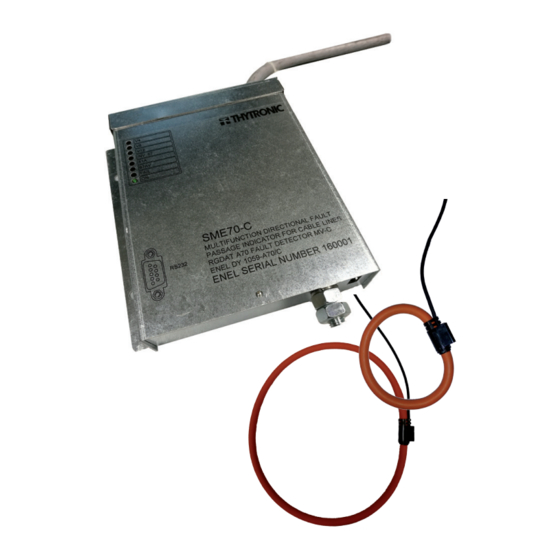
Secondary Stations in order to provide local and remote signalling of short circuit and earth faults that may occur in MV distribution networks. SME70, SME70-C, SME70-M quickly locate the line section affected by the fault thus reducing power outage. -
Page 4: Main Features
Phase Current Sensors Only SME70-C, SME70-M devices use the signal provided by Rogowski sensors: • Two current sensors for measuring two-phase current and one current sensor for measuring re- sidual current or alternately •... - Page 5 Double earth single-phase or phase-phase (short circuit) fault detection function (51) SME70-C, SME70-M ONLY • The phase currents are measured and fault indication is provided when current in at least one phase exceeds the set threshold a: • 100...900 A for multi-phase faults (51) •...
-
Page 6: Technical Data
Reference standards EN 60255-22-3 IEC 60255-22-3 EN 61000-4-3 IEC 61000-4-3 Radiated radio-frequency fields • 80...3000 MHz AM 80% 10 V/m • 900, 1890 MHz Pulse modulated 10 V/m Reference standards EN 60255-22-4 IEC 60255-22-4 EN 61000-4-4 IEC 61000-4-4 SME70, SME70-C, SME70-M-Manual-04-2020... -
Page 7: Mechanical Tests
Pollution degree Reference voltage 250 V Overvoltage category — Certifications Product standards EN 50263 CE Conformity • EMC Directive 2014/30/EC • Low Voltage Directive 2014/35/EC Type tests IEC 60255-1 — Cyber Security • Security Guideline GICT-SGL_12_v01_OCS OT SME70, SME70-C, SME70-M-Manual-04-2020... -
Page 8: Input Circuits
4...20 mA With 67N element active inside the no trip sector 0 mA Accuracy Max load 750 Ω Maximum response time 300 ms CONNECTION TO THE REMOTE CONTROL UNIT Type 9 wires multipolar cable Section 1 mm Length SME70, SME70-C, SME70-M-Manual-04-2020... -
Page 9: Communication Interface
The positive sequence voltage is compared with the threshold. If voltage over the pickup value is detected a start is issued and, after expiry of the associated operate time, a trip command (67N relay) is issued; if however the voltage drop below the threshold the element is restored. SME70, SME70-C, SME70-M-Manual-04-2020... - Page 10 V4, V8, V12 0.8 Un 0.2 Un LED V4 LED V8 LED V12 0.25s Voltage presence (59) Voltage presence (59) Operation The voltage presence is indicated by through the TSV relay and the corresponding LED (V4, V8, V12) SME70, SME70-C, SME70-M-Manual-04-2020...
- Page 11 The residual current is compared with the setting threshold. Currents above the pickup value are detected and a start is issued. After expiry of the associated operate time a trip command is issued (51 relay); if instead the current drops below the threshold, the element it is restored. SME70, SME70-C, SME70-M-Manual-04-2020...
- Page 12 NO TRIP 240° Fig.2 TRIP TRIP >,V > >, t >> > >, V >,V > Operating characteristic time to voltage-residual current Operating characteristic voltage-residual current for directional earth fault element (67N) for directional earth fault element (67N) SME70, SME70-C, SME70-M-Manual-04-2020...
- Page 13 Voltage presence ON Voltage OFF Voltage ON Circuit OPEN CLOSED OPEN CLOSED breaker 67N logic 67N logic Circuit breaker closing on fault Circuit breaker closing on fault with voltage ON before fault with voltage OFF before fault SME70, SME70-C, SME70-M-Manual-04-2020...
- Page 14 • 51 e 59 pulse 0...5000 ms (step 10 ms) Operating mode STANDARD VOLTAGE MONITORING STANDARD MV Voltage At least one voltage ≥ 80% Un INV (UD) delay pulse delay pulse Relay 51 (pulse) Relay 59 (pulse) Relay 67N (bistable) SME70, SME70-C, SME70-M-Manual-04-2020...
-
Page 15: Operation Logic
Note 4 Data concerning the most recent event is stored in the record indicated by the Last event parameter (1...200) Note 5 The counter is increased on each next event; it can be reset by ThySetter command SME70, SME70-C, SME70-M-Manual-04-2020... - Page 16 The same considerations also apply when the sensor is positioned near bends in the cabling. It is recommended that the transformer be placed away from bends in the conductors). SME70, SME70-C, SME70-M-Manual-04-2020...
- Page 17 - n.1 3m rilsan sheath - n.4 Screws - n.4 Shakery washers - n.4 Assembly nuts SME70-M Copper braids Copper braids Copper braids Capacitive Capacitive Capacitive insulator insulator insulator Ø10 SME70-M Ø5.5 N.6 HOLES Ø15 EARTH PHASE SME70, SME70-C, SME70-M-Manual-04-2020...
- Page 18 THYVISOR The Thyvisor sw is a “browser” of data (setting, measure, etc..); it implements an engine that is afford to rebuild the menu set up and the relationships to data concerning all Thytronic protective relays by means of XML files.
- Page 19 Note 1 To change the setting you need to work at session level 1; at level 0 (user) reading settings can not be disabled Note 2 The shown images explain some menu levels; all examples are indicatives and unrealistic. SME70, SME70-C, SME70-M-Manual-04-2020...
- Page 20 Inside the tab Network is possible to find all commands to add protections relay to the network, configure serial port, start and stop a network and configure functions of the relay clicking on the command Protections. Auto add online device Setting of serial port Save network Add/Load offline device SME70, SME70-C, SME70-M-Manual-04-2020...
-
Page 21: Add Device
To manually open configuration window, in case of Off-line programmation, User can click on the “Pro- tection” command. From that window is possible to change all main parameters. They will be stored in memory of SME70 and then become operational only after that the “OK” button has been pressed. SME70, SME70-C, SME70-M-Manual-04-2020... -
Page 22: Firmware Update
• Switch to Level 1 session (Level command from Home tab) • Send the following commands (Commands \ Option menu) right clicking and pressing “Execute” (be sure to Start network from Home tab or press F2) • Set default PAR • Set default REE SME70, SME70-C, SME70-M-Manual-04-2020... - Page 23 SME70 of power MB terminal block COM TS (+24 V) TS 51A TS PRES V capacitive divider Link to remote control TS 67AV unit [UP] COM UD -24 V MA terminal block RS232 Ground Spacer SME70, SME70-C, SME70-M-Manual-04-2020...
- Page 24 CONNECTION DIAGRAM SME70-C, SME70-M normal direction SME70-C SME70-M of power MB terminal block COM TS (+24 V) TS 51A TS PRES V capacitive divider Link to TS 67AV remote control unit [UP] COM UD -24 V I> current sensor MA terminal block I>...
- Page 25 EXTERNAL VIEW - SME70 INDOOR FAMILY To Remote control unit [UP] V 12 IN V . 67 5 1A 6 7 A V F A IL R S 2 32 SME70, SME70-C, SME70-M-Manual-04-2020...
- Page 26 INTERNAL VIEW - SME70 INDOOR FAMILY POWER SUPPLY RELAY RELAY RELAY TERMINAL BOARD (REMOTE CONTROL UNIT) RS232 CYBER TERMINAL BOARD SECURITY (SENSORS) PRESET SME70, SME70-C, SME70-M-Manual-04-2020...
- Page 27 CURRENT SENSORS (SME70-C, SME70-M ONLY) Phase Current Residual Current Residual sensor Connect to MA according to the terminal tag Phase sensors Connect to MA according to the terminal tag Connect to the ground spacer CAPACITIVE INSULATORS (SME70-M ONLY) SME70, SME70-C, SME70-M-Manual-04-2020...
- Page 28 VOLMETRIC SOCKET (SME70-M ONLY) CROSSBAR FOR CAPACITIVE INSULATORS (SME70-M ONLY) SME70, SME70-C, SME70-M-Manual-04-2020...
- Page 29 SHIELDED INTERCONNECTING CABLE (SME70-M ONLY) UP CONNECTION CABLE (FULL SME70 INDOOR FAMILY) SME70, SME70-C, SME70-M-Manual-04-2020...
- Page 30 Headquarters: 20139 Milano - Piazza Mistral, 7 - Tel. +39 02 574 957 01 ra - Fax +39 02 574 037 63 Factory: 35127 Padova - Z.I. Sud - Via dell’Artigianato, 48 - Tel. +39 049 894 770 1 ra - Fax +39 049 870 139 0 www.thytronic.it www.thytronic.com...
Need help?
Do you have a question about the SME70-C and is the answer not in the manual?
Questions and answers