
Subscribe to Our Youtube Channel
Related Manuals for Thytronic SME70-O


Summary of Contents for Thytronic SME70-O
- Page 1 SME70-O FAULT DETECTOR MANUAL SME70 27V1 59V2 SME70 27V1 59V2 SME70 27V1 59V2 SME70-O-Manual-04-2020...
-
Page 2: Warranty
I N T R O D U C T I O N — Scope and liability The functions, technical data, instructions for setting and commissioning of SME70-O devices are explained. This manual has been checked out, however, deviations from the description cannot be completely ruled out, so that no liability in a legal sense for correctness and completeness of the information or from any damage that might result from its use is formally disclaimed. -
Page 3: General Info
The correct detection of the fault direction also occurs in the presence of intermittent faults. SME70-O devices check the voltage of the three phases of the MT line and indicates whether it is ON or OFF; a current converter is also available with an impressed current output of 4...20 mA for sending the phase current measurement to the remote control terminal. -
Page 4: Main Features
The residual voltage is computed through vector sum of phase voltages. Sensors connections The sensors must be connected to the MA RJ45 connectors located inside the SME70-O panel. Remote control unit Remote control unit connections are implemented according with ENEL specification; they are abut- ted to the terminal board MB at the factory according to the connection diagram inside the device cover. - Page 5 5 of the MB terminal board. Endesa Functionality SME70-O permits, setting in \Set\Base\Mode the endesa mode. to enable Endesa functionality. In this mode: • The command of the 51 relay is issued only when, after tripping of thresholds 51,51N or 67NS2, the condition of “Voltage Absent”...
-
Page 6: Technical Data
• U (line-to-line 0 ohm, 18 mF) 1 kV • I/O ports (line-to-ground 40 ohm, 0.5 mF) 2 kV • I/O ports (line-to-line 40 ohm, 0.5 mF) 1 kV Reference standards EN 60255-22-6 IEC 60255-22-6 EN 61000-4-6 IEC 61000-4-6 SME70-O-Manual-04-2020... -
Page 7: Mechanical Tests
IEC 60255-27 Pollution degree Reference voltage 250 V Overvoltage category — Certifications Product standards EN 50263 CE Conformity • EMC Directive 2014/30/EC • Low Voltage Directive 2014/35/EC IEC 60255-1 Type tests — Cyber Security • Security Guideline GICT-SGL_12_v01_OCS OT SME70-O-Manual-04-2020... -
Page 8: Input Circuits
57.5...61.5 Hz (f = 60 Hz) — Integrated outdoor sensors Type CVS-P-24-O RGDAT Rated frequency 50/60Hz Bandwidth 30Hz ... 5kHz Connection to SME70-O • type FTP 8 wires cable • connector RJ45 • length Current Rated current 300A Rated transformation ratio... -
Page 9: Communication Interface
— Residual overvoltage - 59VN (59V0) > threshold 0.01...0.40 En (step 0.01 En) > operate time 0.0...60.0 s (step 0.1 s) Start time 0.045 s TRIP > > General operation time characteristic for the residual overvoltage element - 59V0 t-int-F59N.ai SME70-O-Manual-04-2020... - Page 10 0.02 s Duration of the fault not detected 0.04 s Duration of the fault detected 0.08 s Threshold accuracy ±10% Operate time accuracy ± 10 ms TRIP 0.045 I> General operation time characteristic for the phase overcurrent element - 51 SME70-O-Manual-04-2020...
- Page 11 Accuracy (residual voltage) ±1% Accuracy (residual current) ±15% Angular sectors accuracy (U = 1...120%; I =1...150 A) ±2° (I =1...150 A - V =1...120% E Hysteresis on output by sector ≤ 3° Operate time accuracy ±3% ± 20 ms SME70-O-Manual-04-2020...
- Page 12 • A fault inside the 120...255° sector with the 67NS1 and 67NS2 threshold enabled, drives the 67N relay and 67N LED • A fault inside the 60...120° sector with the 67NS1 and 67NS2 threshold enabled, drives the 51 and 67N relays and 67N LED SME70-O-Manual-04-2020...
- Page 13 ≤ 170 ms Voltage presence ON Voltage OFF Voltage ON Circuit OPEN CLOSED OPEN CLOSED breaker 67N logic 67N logic Circuit breaker closing on fault Circuit breaker closing on fault with voltage ON before fault with voltage OFF before fault SME70-O-Manual-04-2020...
- Page 14 • 51 e 59 pulse 0...5000 ms (step 10 ms) Operating mode STANDARD VOLTAGE MONITORING STANDARD MV Voltage At least one voltage ≥ 80% Un INV (UD) delay pulse delay pulse Relay 51 (pulse) Relay 59 (pulse) Relay 67N (bistable) SME70-O-Manual-04-2020...
-
Page 15: Operation Logic
Note 3 The counter is increased on each next fault; it can be reset by ThySetter command Note 4 Data concerning the most recent event is stored in the record indicated by the Last event parameter (1...200) Note 5 The counter is increased on each next event; it can be reset by ThySetter command SME70-O-Manual-04-2020... -
Page 16: Safety Recommendations
The devices must be installed and put into operation by qualified personnel with experience in high voltage installations. Thytronic assumes no responsibility for damages caused from improper use that does not comply all warning and caution in this manual. In particular the following requirements must be met: •... - Page 17 Nylon junction box n.1 fixing bracket 10 m Nylon for junction box corrugated tube n.5 Nylon corrugated tube fittings n.5 Nylon locknuts M25 n.5 flat gasket for DN28 M25 couplings n.1 connection cable from SME70-O to UP SME70-O-Manual-04-2020...
-
Page 18: A S S E M B L Y S E Q U E N C E
— Installation of couplings on the sensors Verify that the connections and gaskets are correctly fitted; check that the connections are properly tightened and eventually provide for clamping with the aid of an adjustable wrench. flat gasket for DN28 M25 couplings SME70-O-Manual-04-2020... - Page 19 Fasten the junction box on the bracket with the two screws TE M5x10 Stainless Steel and mount couplings: - n.4 Nylon couplings fo corrugated tube - n.4 Nylon locknuts M25 - n.4 flat gasket n.4 nylon couplings for corrugated tube n.4 M25 nylon locknuts n.4 flat gasket SME70-O-Manual-04-2020...
- Page 20 6 m from the ground. The mounting on the substation wall requires the use of suitable expansion anchors (not supplied) 1485 Incoming CVS-P-24-O RGDAT min 500 CVS-P-24-O RGDAT support shelf junction box for sensors junction box SME70-O SME70-O-Manual-04-2020...
- Page 21 The junction box must be mounted on the bracket by means of two screws M5x10 and the fixing to the pole of the set must be carried out through metal clamps (not supplied). 400 547.5 547.5 CVS-P-24-O RGDAT support shelf for sensors junction box junction box SME70-O + UP SME70-O-Manual-04-2020...
- Page 22 • Block the ends of the tube into the couplings previously installed on the SME-UP cabinet. • Fix the tubes with suitable clamps (not supplied). CVS-P-24-O RGDAT support shelf for sensors DN28 Nylon corrugated tube SME70-O Nylon corrugated tube coupling Nylon locknuts M25 flat gasket SME70-O-Manual-04-2020...
- Page 23 • Block the ends of the tube into the couplings previously installed on the SME-UP cabinet. • Fix the tubes with suitable clamps (not supplied). CVS-P-24-O RGDAT DN28 Nylon corrugated tube SME70-O Nylon corrugated tube coupling Nylon locknuts M25 flat gasket SME70-O-Manual-04-2020...
- Page 24 THYVISOR The Thyvisor sw is a “browser” of data (setting, measure, etc..); it implements an engine that is afford to rebuild the menu set up and the relationships to data concerning all Thytronic protective relays by means of XML files.
- Page 25 Note 1 To change the setting you need to work at session level 1; at level 0 (user) reading settings can not be disabled Note 2 The shown images explain some menu levels; all examples are indicatives and unrealistic. SME70-O-Manual-04-2020...
- Page 26 Inside the tab Network is possible to find all commands to add protections relay to the network, configure serial port, start and stop a network and configure functions of the relay clicking on the command Protections. Auto add online device Setting of serial port Save network Add/Load offline device SME70-O-Manual-04-2020...
-
Page 27: Add Device
To manually open configuration window, in case of Off-line programmation, User can click on the “Pro- tection” command. From that window is possible to change all main parameters. They will be stored in memory of SME70 and then become operational only after that the “OK” button has been pressed. SME70-O-Manual-04-2020... -
Page 28: Firmware Update
FIRMWARE UPDATE The command allows upgrading of the firmware. The procedure should only be activated in case of real need in accordance with the instructions provided by Thytronic. WARNING Incorrect operation can cause serious damage to the operation of the device! The operating procedure is scheduled in the following steps: •... -
Page 29: Connection Diagram
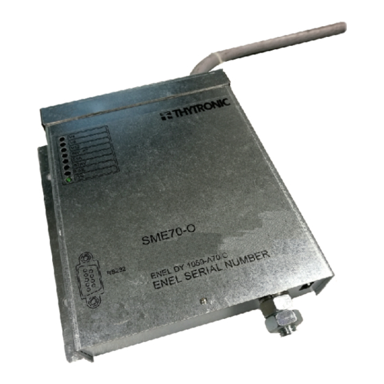
CONNECTION DIAGRAM FEEDER SME70-O COM TS (+24 V) TS 51A TS PRES V TS 67AV Link to remote control unit COM UD -24 V RS232 Male 9 pin connector Female 9 pin connector SME70-O-Manual-04-2020... - Page 30 SME70-O EXTERNAL VIEWS To Remote control unit SME70-O-Manual-04-2020...
- Page 31 SME70-O INTERNAL VIEWS CYBER SECURITY PRESET SME70-O-Manual-04-2020...
- Page 32 CVS-P-24-O RGDAT SENSOR (A) Pin: 1 GND 2 GND 3 TA Pin1 4 TA 5 TV 6 TV 7 N.C. 8 N.C. SME70-O-Manual-04-2020...
- Page 33 CVS-P-24-O RGDAT SENSOR (B) footprint of mounted extension Pin: 1 GND 2 GND 3 TA Pin1 4 TA 5 TV 6 TV 7 N.C. 8 N.C. SME70-O-Manual-04-2020...
- Page 34 SUPPORT SHELF FOR CVS-P-24-O RGDAT SENSORS Ø14 Ø30 Ø14 Unit [mm] SME70-O-Manual-04-2020...
- Page 35 Headquarters: 20139 Milano - Piazza Mistral, 7 - Tel. +39 02 574 957 01 ra - Fax +39 02 574 037 63 Factory: 35127 Padova - Z.I. Sud - Via dell’Artigianato, 48 - Tel. +39 049 894 770 1 ra - Fax +39 049 870 139 0 www.thytronic.it www.thytronic.com...
Need help?
Do you have a question about the SME70-O and is the answer not in the manual?
Questions and answers