
Related Manuals for AC Air Technology T1X3 Aircraft Tug


Summary of Contents for AC Air Technology T1X3 Aircraft Tug
- Page 1 MODEL: T1X3 Aircraft Tug Instruction Manual 95490 Rev. E World’s First Portable, Remote-Control Aircraft Tugs...
-
Page 2: Table Of Contents
Table of Contents 1. Components ............... 3 1-1 Components in the Box ................. 3 1-2 Tug Components ................... 4 1-3 Remote Control Components ..............5 1-4 Charger Components ................6 1-5 Spare Parts ................... 7 1-6 Track Tools .................... 8 1-7 On-Board Parts Box ................ -
Page 3: Components
1. Components 1-1 Components in the Box Accessory Cradle Roller Radio Charger Radio Transmitter Battery Tray Tug Charger Owners Manual Spare Parts Bag... -
Page 4: Tug Components
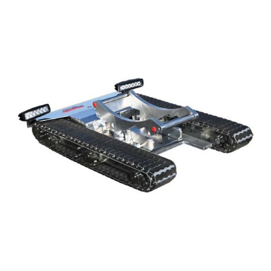
1. Components 1-2 Tug Components Rear Cradle Gate Lazy Susan Left Track Assembly Main Plate Wheel Cradle Side Plates Right Track Assembly Wheel Ramp Power Switch Tug Charger Connection Electronics Cover... -
Page 5: Remote Control Components
1. Components 1-3 Remote Control Components Power Indicator Control Stick 3 Speed Toggle Light Switch Lazy Susan Lock & Cradle Release Switch Charging Indicator LED ON/OFF Switch Charging Jack Lanyard Anchor Warning: The control stick on the remote controller is very sensitive and will cause the tug to move if it is moved accidentally. -
Page 6: Charger Components
1. Components 1-4 Charger Components Tug Charger Tug Connection Charging Indicator 110V Power Connection Remote Control Charger 110V Power Connection Radio Connection... -
Page 7: Spare Parts
1. Components 1-5 Spare Parts Spare Track Parts Retainer Clips Pins Links Treads Track Install Tools Fuses 4 Amp Light Fuse 10 Amp Circuit Board Fuse Retainer Clip Tool... -
Page 8: Track Tools
1. Components 1-6 Track Tools The track tools are used to assist in the installation of new tracks. This section is intended to show how the tools are used only. A detailed instruction guide is provided when purchasing new tracks. Refer to that instruction guide when installing new tracks. - Page 9 The Track Pin Tools are used to assist in the installation of new tracks when the they are too tight making it diffi cult to align the pin holes. Insert the track pin tools on the inside and outside adjacent pins to the missing pin hole.
-
Page 10: On-Board Parts Box
1. Components 1-7 On-Board Parts Box The On-Board Parts Box contains spare track links, clips, and tools to quickly replace or repair tracks. These components are located on-board the tug, underneath the elec- tronics cover. Parts Box Track Links Rotoclip Install Tool Rotoclips... -
Page 11: Start-Up Guide
2. Start-Up Guide 2-1 Remote Control Operation 1. Switch the remote control ON. The power indicator light turns on and the remote control beeps once. If this does not happen, check the remote control battery con- nection for proper installation. When the battery level is low, the remote control will begin to beep repeatedly, signaling to replace or recharge the batteries. -
Page 12: Operating The Tug
2. Start-Up Guide 2-2 Operating the Tug 1. Before turning on the tug, make sure the tracks and bottom of the tug are free from obstruction. 2. Turn the tug on using the ON/OFF switch. There will be a short series of beeps and then the ON/OFF switch will illuminate red to show the tug is on. - Page 13 6. After lifting the tug off of the ground for any reason or taking it in and out of your air- craft, you must check the sprockets for proper seating along the tracks. If the sprock- et is not properly seated it could result in damage to the track. Check sprockets for proper seating and alignment.
-
Page 14: Adjusting The Wheel Cradle (Pre-Load Setup)
2. Start-Up Guide 2-3 Adjusting the Wheel Cradle (Pre-Load Setup) Note: You do not want the tire to be too tight inside the wheel cradle. There should be space for tire size variations. After confi guring the wheel cradle, drive the tug under the tire to verify the wheel cradle is setup correctly and to ensure the cradle lock is fully engaged. -
Page 15: Confi Guration B: For 14.50" Maximum Outside Tire Diameter
Confi guration B: For 14.50” Maximum Outside Tire Diameter 1B. For Confi guration B the supplied Accessory Cradle Roller will be needed. Accessory Cradle Roller 2B. Disassembly the Accessory Cradle Roller. ii. Pull out Inside Rod i. While holding the other end fi... - Page 16 4B. Install the Accessory Cradle Roller into the wheel cradle’s First Position (position shown is step 3B above) by holding the outside roller in between the wheel cradle and sliding the inside rod through one end of the wheel cradle and out the other. Secure the Accessory Cradle Roller with the red knob.
-
Page 17: Confi Guration C: For 8.25" Maximum Outside Tire Diameter
Confi guration C: For 8.25” Maximum Outside Tire Diameter 1C. For Confi guration C the supplied Accessory Cradle Roller will be needed. Accessory Cradle Roller 2C. Disassembly the Accessory Cradle Roller. ii. Pull out Inside Rod i. While holding the other end fi... - Page 18 4C. Install the Accessory Cradle Roller into the wheel cradle’s Second Position (position shown is step 3C above) by holding the outside roller in between the wheel cradle and sliding the inside rod through one end of the wheel cradle and out the other.
-
Page 19: Adjusting The Tire Guide Spacers
2. Start-Up Guide 2-4 Adjusting the Tire Guide Spacers Adjustment Pin Tire Guide Spacers 1. If the tire guide spacers are in the widest position and your tire does not fi t or it is too close of a fi t remove the tire guide spacers and adjustment pins. Widest Position... - Page 20 2. Adjust the tire guide spacers by removing the adjustment pins and sliding the spac- ers towards each other. Ideally the tire guide spacers should be moved the same distance on each side to keep your tire centered in the cradle. The distance between the dovetail spacers should equal the width of your tire plus one inch maximum.
-
Page 21: Loading The Aircraft Wheel
2. Start-Up Guide 2-5 Loading the Aircraft Wheel WARNING: DO NOT SIT IN THE PLANE WHILE DRIVING THE TUG. TO PREVENT GOING BEYOND YOUR STEERING LIMITS IT IS HIGHLY RECOMMENDED THAT YOU LOCK THE LAZY SUSAN FROM ROTATING WHILE GOING UP AND DOWN HILLS AND MOVING ALONG A STRAIGHT PATH. - Page 22 2. Drive the tug to line up the aircraft tire with the center of the wheel ramp. It may be necessary to apply a little pressure with your foot to the top of the tug shroud to get the wheel started onto the tug. Aircraft Tire Wheel Cradle Ramp in down position...
- Page 23 If the issue persists call or e-mail AC Air Technology tech sup- port for further assistance.
-
Page 24: Unloading The Aircraft Wheel
2. Start-Up Guide 2-6 Unloading the Aircraft Wheel 1. Toggle the Lazy Susan Lock Switch in the middle position and rotate the tug under the aircraft tire until the wheel ramp is facing the front of the tug. Push the tug so the rear gate is slightly pushing against the tire. - Page 25 2. Hold the latch release switch on the radio controller and slightly rotate the tug under the tire until the latch releases the rear gate. You will need to visually verify that the latch is released. This may require rotating the tug back and forth slightly until the latch releases.
- Page 26 4. Continue driving the tug away from the tire until the tire is completely off of the tug. You can stop holding the latch release switch after the tire is off of the tug. Continue Driving the Tug Away From Tire Tire Completely Off...
-
Page 27: Adjusting Track Tension
2. Start-Up Guide 2-7 Adjusting Track Tension Track tension may need to be adjusted after several hours of use. Follow the instruc- tions below for each track. 1. Remove 6 cover screws to remove the track plastic cover. Track Cover Screws Outside Track Cover Right Side Left Side... - Page 28 3. Push the rail end forward using a small pry bar to tighten up the track. There should be a 1/2” of play at the center of the track. Do not over tighten the tracks. 1/2” Up and Down Play at Center of Track 4.
-
Page 29: Charging The Tug
2. Start-Up Guide 2-8 Charging the Tug 1. Before charging your tug, the remote controller and tug should both be turned OFF. Tug Charging Jack Power Switch 2. Plug charger into charging jack and into a wall socket. The plug can only be inserted in one direction. -
Page 30: Charging The Remote Control
2. Start-Up Guide 2-9 Charging the Remote Control WARNING: Only use the supplied charger to charge the controller when using the supplied batteries or the following: - 1200mAh to 2200 mAh Ni-MH or Ni-Cd ‘AA’ Rechargeable Batteries Using the remote control charger with alkaline batteries installed can damage the con- troller. -
Page 31: Replacing Remote Control Batteries
2. Start-Up Guide 2-10 Replacing Remote Control Batteries 1. Before changing the remote control batteries, the remote controller and tug should be turned OFF. 2. Remove 2 screws on the back cover of the remote controller then remove the back cover. - Page 32 4A. Replace the batteries by purchasing a new shrink wrapped Note: A shrink wrapped battery pack can battery pack from AC Air Technology be purchused from AC Air Techology to or installing the supplied battery tray replace the installed battery tray. To use a and purchasing 6 rechargable ‘AA’...
-
Page 33: Troubleshooting
3. Troubleshooting The troubleshooting guide is divided into three sections: Tug, Remote Controller, Wheel Cradle. Refer to the images and descriptions below as they are mentioned throughout the text. Servo Speed Control Latch Mechanism Radio Receiver... -
Page 37: Warranty
In no event shall the liability of AC Air Technology exceed the individual price of the product on which liability is asserted. AC Air Technology has no control of the set up, ap- plication, use, modifi cation, or misuse of this product, thus no liability shall be assumed or ac- cepted for any resulting damage or injury.
Need help?
Do you have a question about the T1X3 Aircraft Tug and is the answer not in the manual?
Questions and answers