Table of Contents
Advertisement
Quick Links
Advertisement
Table of Contents

Related Manuals for Wittenstein attocube AMC100


Summary of Contents for Wittenstein attocube AMC100
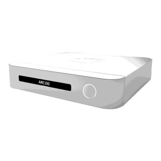
- Page 1 User Manual AMC100...
- Page 2 Firmware Version: Modified: 02/2021 Products: AMC100 | attoDISCOVERY Software | AMC Webserver Application | MOVE © 2021 attocube systems AG. Product and company names listed are trademarks or trade names of their respective companies. Any rights not expressly granted herein are reserved. ATTENTION: Specifications and technical data are subject to change without notice.
-
Page 3: Table Of Contents
Table of Contents Page 1 Table of Contents 1 Notes on This Manual ......................4 1.1 Purpose and Availability ....................4 1.2 Symbols and Conventions ..................... 4 1.2.1 Warning Notes ....................4 1.2.2 Symbols ......................4 1.2.3 Information mark up ..................5 2 Declarations ........................... - Page 4 Page 2 Table of Contents 6.3.3 "Operation" Screen ..................37 7 Device Start-Up ........................40 7.1 Switching On the Device ....................40 8 Operation ..........................41 8.1 Restoring Former Axis Selection .................. 41 8.2 Labeling Entities......................42 8.2.1 Labeling Device ....................42 8.2.2 Labeling Axes ....................
- Page 5 Table of Contents Page 3 11.3.8 Configuring Remote Controller ................ 66 11.4 Rotation Compensation Feature Package ..............66 11.4.1 Rotation Compensation Setup ................. 66 11.4.2 Rotation Compensation Feature ..............67 11.4.3 Importing, Exporting and Updating Compensation File ........67 11.4.4 Enabling and Disabling the Compensation ............68 11.5 AMC/IDS Closed Loop Feature Package ..............
-
Page 6: Notes On This Manual
Page 4 Notes on This Manual Notes on This Manual Purpose and Availability This user manual applies to the AMC100, also referred to as "device" in this document. The user manual explains the installation and operation of the device. It contains instructions for the appropriate use and the maintenance of the device. -
Page 7: Information Mark Up
Notes on This Manual Page 5 General hazard! May cause injury or death if the suitable precautions are not taken. May cause damage to the device, the process, or the surroundings if the suitable precautions are not taken. Information mark up 1.2.3 To improve traceability, the following design conventions are used in this document: Names of elements like folders, files, screens, options etc. -
Page 8: Declarations
Page 6 Declarations Declarations Declaration of Conformity 2.1.1.1 For Customers in Europe This equipment has been tested and found to comply with the EC Directives 2014/30/EU "EMC Directive" and 2014/35/EU "Low Voltage Directive". Compliance was demonstrated by conformance to the following specifications, which have been listed in the Official Journal of the European Communities: Safety EN61010-1:2010 EMC EN61326-1: 2013... -
Page 9: Waste Electrical And Electronic Equipment (Weee) Directive
Declarations Page 7 Waste Electrical and Electronic Equipment (WEEE) Directive 2.2.1.1 Compliance As required by the Waste Electrical and Electronic Equipment (WEEE) Directive of the European Community and the corresponding national laws, attocube offers all end users within the European Union (EU) the possibility to return "end of life" units without incurring disposal charges. -
Page 10: Safety Information
Page 8 Safety Information Safety Information Important Warnings WARNING Risk of electric shock! Inappropriate handling of the device may cause death, severe injury or material damage. Never remove the device's protective covers or attempt any repair or adjustment! Immediately shut off the device, disconnect the mains supply and contact attocube in case of any suspected malfunction! Never connect any cabling to the electronics when the outputs are enabled! Be careful not to create short-circuits on the connectors or anywhere in the... -
Page 11: Labels On The Device
Safety Information Page 9 Labels on the Device The following labels can be found on the device. Figure 1 Labels on the device Label Explanation AMC100 type label QR-Code Link to device support Serial number Type Product name Power Rated power Manufactured Year of manufacture FCC conformity... -
Page 12: Device Description
Page 10 Device Description Device Description Intended Use The AMC100 is a controller for the simultaneous operation of up to three positioners out of attocube’s EC* series Positioners. Depending on the customer’s choice, the set of positioners controlled can be an arbitrary combination of one to three dimensional, linear, rotary or goniometric positioners with open loop or closed loop feedback. -
Page 13: Pc Requirements
Device Description Page 11 The following environmental limits have to be observed when operating the device. Parameter Value Supply voltage 90 V to 240 V AC, +/- 10 % Line frequency 50 Hz to 60 Hz Operational area Indoor use only Maximum altitude 2000 m Minimum temperature... -
Page 14: Hardware Interfaces
Page 12 Device Description Hardware Interfaces Connector Panel 4.5.1 Figure 2 Connector panel GPIO socket Trigger signal connection (in and out) Ethernet uplink socket Network connection Ethernet downlink socket Daisy-chaining connection (/PRO upgrade required) USB socket USB-A for multiple connection purposes Sensor IN socket Interferometer input connection Power supply socket... -
Page 15: Positioner Control Cable
Device Description Page 13 Positioner Control Cable 4.5.2 Positioners for room temperature use are delivered with the following positioner control cable. Figure 3 Positioner control cable for room temperature use Figure 4 Positioner control cable for connection to vacuum feedthrough The pins of the device’s positioner control cables are assigned as follows: 26 pin D-sub socket Sensor I/O... - Page 16 Page 14 Device Description NOTE When connecting customized cables certain cabling restrictions must be obeyed in order to guarantee an optimal positioning and detecting performance. Do not to connect cabling with a wire resistance > 5 Ω. Use EMV housings as enclosure for the D-sub connectors. Use extra shielded twisted pair wires for the piezo voltage supply.
-
Page 17: Device Setup
Device Setup Page 15 Device Setup Unpacking and Positioning 1. Carefully unpack the device and its accessories. 2. Inspect the device and the accessories for any damage. Contact attocube in case of any detected damage. 3. Place all components on a flat and clean surface. NOTE Inadequate positioning may lead to malfunctions or damage the device. -
Page 18: Connecting To Pc Via Usb
Page 16 Device Setup Connecting to PC via USB The PC fulfills the requirements specified in section 4.4. You are logged in to the PC with administrator rights. 1. Plug in the USB connector of the USB-to-Ethernet adapter (part of the delivery) into the USB port of your PC. -
Page 19: Connecting Positioner
Device Setup Page 17 NOTE Make sure the chosen IP is available for your network and is not already in use. 4. Click on [Apply]. Connecting Positioner CAUTION Wrong connection! Inadequate connections may cause injury and are likely to damage the device or interfere with an appropriate functioning. - Page 20 Page 18 Device Setup When the software is started for the first time, a folder named attocube containing a file named staticDevices.json is created in your user's folder at the PC. In this file you can specify IP addresses of controllers that will automatically be connected, even if they are not directly connected to the PC's network subnet.
-
Page 21: Graphical User Interfaces
Graphical User Interfaces Page 19 Graphical User Interfaces attoDISCOVERY Software The attoDISCOVERY software is a PC-based application for controlling and analyzing positioner movements. Access If the software is installed it can be called up via the respective desktop icon or start menu entry. - Page 22 Page 20 Graphical User Interfaces 6.1.1.2 Controller Tile The controller tile displays several controller and connection properties. allows you to label the controller and the axes, see section 8.2. allows you to select the axes to be displayed and controlled on the "Operation" screen, see section 6.1.2.
-
Page 23: Operation" Screen
Graphical User Interfaces Page 21 "Operation" Screen 6.1.2 The "Operation" screen is the screen where the actual positioning process takes place. Access The "Operation" screen can be accessed via the "Find Devices" screen's [Next] button. 6.1.2.1 Overview The "Operation" screen displays the formerly selected axes (Figure 7/4), each in a separate tile. - Page 24 Page 22 Graphical User Interfaces Controls Figure 9 Axis tile, operation view (fully expanded) Axis activation checkbox Activate or deactivate the axis, see section Configuration link Open the axis' configuration view Axis status bar Read out the axis' current status, see table below Open loop movement controls Control open loop positioning movements, see table below and section...
- Page 25 Graphical User Interfaces Page 23 Positioner reached insurmountable obstacle in positive direction Positioner reached insurmountable obstacle in negative direction Positioner is in target range and grounded Rotation Compensation feature is compensating X/Y runout Positioning controls The following control elements (Figure 9/4) are available for open loop movement control.
- Page 26 Page 24 Graphical User Interfaces Access Changes applied in the axis tile's configuration view are applied automatically, i. e. without having to be confirmed by pressing a respective button. The axis tile's configuration view can be accessed via the operation view's configuration link (Figure 9/2).
-
Page 27: Webserver Application
Graphical User Interfaces Page 25 Webserver Application The webserver application is a browser-based application for controlling and analyzing positioner movements as well as for the controller device's configuration and maintenance. Access If PC and device are connected to the same LAN and subnet, the webserver application can be started by typing one of the following information into a browser's address line: the device's IP address the device's serial number (without slashes) followed by .local... - Page 28 Page 26 Graphical User Interfaces NOTE Position values for EC* positioners are specified in nanometers or millidegrees, respectively. Controls Figure 12 Axis tile, operation view (fully expanded) Axis activation checkbox Activate or deactivate the axis, see section Configuration link Open the axis' configuration view Axis status bar Read out the axis' current status, see table below Open loop movement controls...
- Page 29 Graphical User Interfaces Page 27 6.2.1.3 Axis Tile, Configuration View The options and functions available in the axis tile's configuration view depend on the device configuration and the positioners you employ. It allows you to specify the positioner type. adapt various positioner performance options. read out certain axis properties.
-
Page 30: Configuration" Screen
Page 28 Graphical User Interfaces "Configuration" Screen 6.2.2 On the "Configuration" screen you can adapt certain controller and connection properties. update the device's firmware. upgrade its feature package. Access The "Configuration" screen can be accessed via the [Configuration] button in the application's header and via the [Device Page] button on the attoDISCOVERY's controller tiles (Figure 7/6). - Page 31 Graphical User Interfaces Page 29 6.2.2.2 "Networking" Section In the "Networking" section you can adapt the network settings used by the device for connection to a LAN. Controls Figure 15 "Networking" section, static configuration "IP mode" field Select the IP mode (default: DHCP) "IP address"...
-
Page 32: Interface" Screen
Page 30 Graphical User Interfaces "Interface" Screen 6.2.3 On the "Interface" screen, the settings for incoming and outgoing trigger communication can be configured each in a separate tile. The tiles are divided in three sections corresponding to the axes. For the parameters and value ranges that are related to a certain protocol, consult section 11.1. - Page 33 Graphical User Interfaces Page 31 6.2.3.2 "Real Time Input" Tile On the "Real Time Input" tile you set the communication mode and the parameters for the interpretation of incoming position commands. To allow you a comfortable adjustment of the parameters, the real time input is not applied until it is activated explicitly.
-
Page 34: About" Screen
Page 32 Graphical User Interfaces 6.2.3.4 "Real Time Output" Tile, "Axis" Section In the "Axis" section you adapt the signal type for trigger output communication, and its parameters. Controls Figure 20 "Real Time Output" tile, "Axis" section "Mode" field Select output mode Parameter fields Adapt output parameters (vary according to output mode) -
Page 35: Controller Configuration" Screen
Graphical User Interfaces Page 33 Figure 21 "About" screen, detail "Manufacturer" section Read out manufacturer information "Version" section Read out device information [System reboot] Reboot device [Factory reset] Restore factory settings (see 10.2.2) "On-Device Features" section Read out active features and upgrades "Controller Configuration"... - Page 36 Page 34 Graphical User Interfaces Controls Figure 22 "Controller Configuration" screen Remote controller status Read out remote controller status section [Disconnect Controller] Unpair / remove remote controller from device Button function fields (stepwise Select stepwise movement function for the respective movement) remote controller button [Back to Navigation]...
-
Page 37: Move Software
Graphical User Interfaces Page 35 MOVE Software Installing the Software MOVE 6.3.1 Connect the USB flash drive contained in the scope of delivery to your PC. On your PC, open the Windows explorer and navigate to the USB flash drive’s folder. Copy the folder "MOVE"... - Page 38 Page 36 Graphical User Interfaces Figure 24 "Find Devices" screen, detail [Next] [Refresh list] Controller tile To refresh the list of controllers, click [Refresh list] in the header of the "Find Devices" screen (Figure 24/2). 6.3.2.2 Controller Tile The controller tile displays several controller and connection properties.
-
Page 39: Operation" Screen
Graphical User Interfaces Page 37 "Operation" Screen 6.3.3 The "Operation" screen is the screen where the actual positioning process takes place. Access To open the "Operation" screen, click [Next] (Figure 24/1) in the header of the "Find Devices" screen. [Next] is not available unless you have selected at least one axis. 6.3.3.1 Overview The "Operation"... - Page 40 Page 38 Graphical User Interfaces Figure 27 Axis tile, operation view Axis activation checkbox Axis name Axis control field Configuration link Axis status bar 6.3.3.3 Closed loop Positioning To open the closed loop positioning control elements, click [Closed Loop] (Figure 27/3) on the axis tile’s operation view.
- Page 41 Graphical User Interfaces Page 39 [Move in positive direction] [Move to target] Target setting field Reference position display 6.3.3.4 Axis Tile, Configuration View To open the configuration view of the axis tile, click on the configuration link (Figure 27/4) in the header of the tile’s operation view.
-
Page 42: Device Start-Up
Page 40 Device Start-Up Device Start-Up Switching On the Device Press the device's power button ( Figure 5/1). Start up your PC. -
Page 43: Operation
Operation Page 41 Operation In the course of this section, instructions on the fulfillment of some typical application tasks are given. For a concise description of all of the device's controlling functions, see section 5. Restoring Former Axis Selection When starting the software, attoDISCOVERY/MOVE Software automatically checks the connected networks for devices (identified by serial number) that were also connected when the software ran the last time. -
Page 44: Labeling Entities
Page 42 Operation Labeling Entities The options to label devices and axes provide a way to increase transparency, especially when working with the same experimental arrangements over larger periods of time or with varying personnel. Labeling Device 8.2.1 The "Find Devices" screen is opened, see section 6.1.1. attoDISCOVERY 1. -
Page 45: Activating And Deactivating Axis
Operation Page 43 The "Configuration" screen is opened, see section 6.2.2. WebApp 1. In the "Device Name" section, click on the name field of the axis to be labeled (Figure 16/2). 2. Type in the axis name of your choice. 3. -
Page 46: Specifying Positioner Type
Page 44 Operation The "Navigation" screen is opened, see section 6.2.1. WebApp To activate an axis, check the axis activation checkbox (Figure 12/1) of the corresponding axis tile. → The axis is activated. To deactivate an axis, uncheck the axis activation checkbox (Figure 12/1) of the corresponding axis tile. -
Page 47: Loading Standard Axis Parameters
Operation Page 45 Examples for adjustable actuator parameters are: the number of steps that are implemented with each stepwise move (/PRO upgrade required) the range in which a positioner is regarded as "in target" whether the positioner stops the attempt to move when it is confronted with physical obstacles Adjustable sensor parameters are: the sensor activity itself... -
Page 48: Open Loop Positioning
Page 46 Operation → A file explorer opens. 2. Navigate to the desired configuration file's folder. 3. Click on the file and confirm. → The axis configuration is uploaded and applied. Open loop Positioning The open loop positioning mode operates without position feedback from the positioner. The position on the axis can be varied without any absolute position information. -
Page 49: Controlling Movements
Operation Page 47 1. To adapt the step size, type in the desired value into the amplitude setting field (Figure 12/5). 2. To adapt the step repetition rate, type in the desired value into the frequency setting field (Figure 12/6). 3. -
Page 50: Closed Loop Positioning
Page 48 Operation Closed Loop Positioning The closed loop positioning mode operates with active position feedback from the positioner. NOTE Closed loop positioning is only available for positioners with /NUM or /NUM+ encoding. Refer to the specification sheets of the positioner for information on the motion specifications in closed loop mode. -
Page 51: Moving To Defined Target
Operation Page 49 The "Navigation" screen is opened, see section 6.2.1. WebApp The respective axis is activated, see section 8.3. The axis tile's operation view is opened. Closed loop positioning is activated, see section 8.5.1. 1. Into the distance field (Figure 12/11), type in the desired absolute movement distance (in µm). -
Page 52: Search And Move To Reference Mark
Page 50 Operation 2. Click on the "Move to target" button (Figure 28/6). → The positioner is moved to the defined target position. Search and Move to Reference Mark 8.5.4 Searching the built in reference mark and / or moving to it. WebAPP ... -
Page 53: Update, Upgrade And Maintenance
Update, Upgrade and Maintenance Page 51 Update, Upgrade and Maintenance All update, upgrade and maintenance procedures are carried out in the webserver application. NOTE There are no user serviceable parts inside the controller! NOTE Please refer to the manual of the remote controller for information on its maintenance requirements. -
Page 54: Updating Firmware
Page 52 Update, Upgrade and Maintenance Updating Firmware attocube provides occasional updates in the form of image files. The files are delivered in a zip folder. attocube informs you when an update for your device is available. NOTE Unauthorized updates can lead to a permanent malfunction and are not covered by attocube's warranty. -
Page 55: Upgrading Device
Update, Upgrade and Maintenance Page 53 Upgrading Device To increase your performance using the AMC300, attocube provides you with additional features and upgrades. License files are delivered for this purpose. Contact attocube for available upgrades. The license file has been downloaded and stored to your PC. ... -
Page 56: Troubleshooting
Page 54 Troubleshooting Troubleshooting NOTE Unauthorized error handling may result in permanent malfunction and is not covered by attocube's warranty. Do not take any action not proposed for troubleshooting in this document. If problems occur that are not mentioned in this section, contact attocube for help. If the problems cannot be solved by the proposed action, contact attocube for help. -
Page 57: Physical Network Connection Present
Troubleshooting Page 55 Physical Network Connection Present 10.2 Follow the instructions in this section to solve problems when the device is connected to the network. Accessing Webserver Application 10.2.1 If you cannot access to the device using the webserver application with the right IP address, take the following steps until the problem is solved: 1. -
Page 58: Physical Network Connection Not Present
Page 56 Troubleshooting Physical Network Connection Not Present 10.3 If no network connection to the device is available, an USB flash drive can be used to perform some basic problem solving tasks. NOTE The USB flash drive must be FAT32-formatted. Reading out Network Settings 10.3.1 ... -
Page 59: Resetting Device To Factory Defaults
Troubleshooting Page 57 Resetting Device to Factory Defaults 10.3.3 This section provides information on how to reset the device to the factory defaults. The first subsection instructs you on taking precautions to preserve the network settings when a reset is performed. -
Page 60: Measuring The Positioner Performance
Page 58 Troubleshooting Measuring the Positioner Performance 10.4 In case a positioner or positioner cable damage is suspected, some significant aspects of the positioner's performance can be measured. The "Operation" screen is opened, see section 6.1.2. attoDISCOVERY The respective axis is activated, see section 8.3. ... -
Page 61: Optional On-Device Features And Upgrades
Optional On-Device Features and Upgrades Page 59 Optional On-Device Features and Upgrades attocube offers various upgrades to facilitate and improve your work with the device. Contact attocube for available features and upgrades. /IO Feature Package 11.1 The /IO feature upgrade allows you to trigger positioning movements by input signals. - Page 62 Page 60 Optional On-Device Features and Upgrades Protocol function AquadB Trigger Stepper Error+ Axis 2 Step-Pulse+ Step-Pulse- DOWN+ Direction+ Input DOWN- Direction- Error+ Error+ Error+ Trigger + Output Trigger - Error+ Axis 3 Step-Pulse+ Step-Pulse- DOWN+ Direction+ Input DOWN- Direction- Error+ Error+ Error+...
-
Page 63: Output Modes And Parameters
Optional On-Device Features and Upgrades Page 61 Output Modes and Parameters 11.1.2 For outgoing communication, the following communication protocols are supported: AquadB Trigger The output mode and parameters can be adjusted on the webserver application's "Interface" screen, see section 6.2.3. 11.1.2.1 AquadB According to the logic of AquadB, the signals on lines A and B designate the increment of the position change. -
Page 64: Input Modes And Parameters
Page 62 Optional On-Device Features and Upgrades Input Modes and Parameters 11.1.3 For incoming communication, the following communication protocols are supported: AquadB Stepper Trigger The input mode and parameters can be adjusted on the webserver application's "Interface" screen, see section 6.2.3. 11.1.3.1 AquadB According to the logic of AquadB, the signals on lines A and B designate the increment of the position change. -
Page 65: Pro Feature Package
Optional On-Device Features and Upgrades Page 63 /PRO Feature Package 11.2 The /PRO feature activates the following enhanced features: controlling multiple devices with one single attoDISCOVERY application daisy-chaining via the device's Ethernet up- and downlink sockets setting the number of steps that are implemented with each stepwise move setting the DC level for manual position adjustment activating end-of-travel detection stopping movement on end-of-travel... -
Page 66: Switching On The Remote Controller
Page 64 Optional On-Device Features and Upgrades [L1] button (configurable) [L2] button (configurable) [SHARE] button Pair the remote control with the device (simultaneously hold the [SHARE] and the PS button) Light bar Indicates the active profile [OPTIONS] button Switch profile [R2] button (configurable) [R1] button... -
Page 67: Establishing A Wireless Connection
Optional On-Device Features and Upgrades Page 65 Establishing a Wireless Connection 11.3.4 Plug the Bluetooth receiver (part of the delivery) into the device's USB socket (Figure 2/4). Pairing Remote Controller and Device 11.3.5 Pairing is not required when the remote controller is connected via cable. ... -
Page 68: Configuring Remote Controller
Page 66 Optional On-Device Features and Upgrades Configuring Remote Controller 11.3.8 The keys of the remote controller can be assigned functions according to your individual controlling preferences. The profile activated for controlling is independent from the profile that is selected for configuration. -
Page 69: Rotation Compensation Feature
Optional On-Device Features and Upgrades Page 67 Rotation Compensation Feature 11.4.2 To ensure that the rotation compensation feature is activated, on the AMC, please check if the feature is listed among the other on-device features on the “About” screen in the WebApp (Figure 38). -
Page 70: Enabling And Disabling The Compensation
Page 68 Optional On-Device Features and Upgrades 1. To export the currently loaded compensation File, press the “Save LUT as..” button in the compensation file information box (see point above) Figure 40 Rotation compensation information box 11.4.3.3 Compensation File Update Updating the positioner offset values that are stored in the compensation file: The offset values are the ones that are absolutely added on the relative compensation LUT information. -
Page 71: Amc/Ids Closed Loop Feature Package
Optional On-Device Features and Upgrades Page 69 Figure 41 Enabled Rotation Compensation 11.4.4.1 Enabling the Compensation Webapp The “Navigation” screen is opened. 1. To enable the rotation compensation, set the „Enabled“ checkbox. NOTE When the rotation compensation is enabled, the linear positioners automatically drive to a position that is the sum of their individual offset value and the compensation value. -
Page 72: Amc/Ids Closed Loop Setup
Page 70 Optional On-Device Features and Upgrades AMC/IDS Closed Loop Setup 11.5.1 For information about the general setup of the IDS3010, please refer to the manuals provided with the interferometric sensor. The network and HSSL cables should be used for the connection between AMC100 and IDS3010. - Page 73 Optional On-Device Features and Upgrades Page 71 Figure 43: Axis tile, Closed loop settings Sensor Type selection field Inverse IDS direction checkbox Motion Control Threshold setting field Stop on IDS stop limit checkbox Lower stop limit setting field Upper stop limit setting field 11.5.3.1 Sensor Type selection Sensor type selection for the closed loop positioning (NUM or IDS).
- Page 74 Page 72 Optional On-Device Features and Upgrades 2. To deactivate the option "inverse IDS direction", uncheck the inverse IDS direction checkbox (Figure 43/2). NOTE The option “inverse IDS direction” is available if the IDS is the sensor source. Per default, this function is deactivated. Check the IDS measurement direction immediately after setup by moving the positioner stepwise in one direction.
-
Page 75: Ids Control
Optional On-Device Features and Upgrades Page 73 NOTE The option "stop on IDS stop limit" by default is deactivated. The limit settings are 0 pm by default. After the first change of these settings, the values will be saved for the next measurements. The upper and lower IDS stop limit settings will be adjusted by changing the reference position (refer to chapter 11.5.5.1). - Page 76 Page 74 Optional On-Device Features and Upgrades Measured refractive index display (determined from ECU parameters) Used refractive index display (from ECU or manual set) NOTE These functions are disabled if the IDS3010 is not connected to the AMC100. 11.5.4.1 IDS Pilot Laser Enabling pilot laser (visible red laser) to ease the optical alignment.
- Page 77 Optional On-Device Features and Upgrades Page 75 NOTE Optics alignment function is applied to all axes simultaneously. We recommend the interferometric contrast (in per mil ‰) to be higher than 500 ‰. Moreover, the target as well as the sensor head should be adjusted to achieve relative constant alignment signal over the whole measurement range.
-
Page 78: Closed Loop Functions
Page 76 Optional On-Device Features and Upgrades Closed Loop Functions 11.5.5 After distance measurement initialization, the closed loop positioning can be applied. For general closed loop operation please refer to chapter 8.5. The IDS specific closed loop functions are described below. 11.5.5.1 Reset Axis According to the external location of the IDS sensor source, the reference position of the axis is freely selectable. -
Page 79: System Integration
System Integration Page 77 System Integration The device can be integrated with external systems or devices by combining it with third party hardware establishing incoming and outgoing trigger connections (/IO upgrade required), see section 11.1 controlling it with individual software interfaces (see interface manual). CAUTION General hazard! Inadequate hardware connections may cause injury and are likely to damage the device or... - Page 80 Page 78 System Integration...
- Page 81 attocube systems AG Eglfinger Weg 2 85540 Haar, Germany Phone: +49 89 420 797 0 E-Mail: info@attocube.com www.attocube.com For technical queries, contact: support@attocube.com Regional US Sales Representatives: West Coast: Arcadia, CA Phone: +1 510 631 2154 Southwest: Henderson, NV Phone: +1 510 631 1784 Midwest: Delaware, OH Phone: +1 510 631 133...
Need help?
Do you have a question about the attocube AMC100 and is the answer not in the manual?
Questions and answers