Table of Contents
Advertisement
Quick Links
Advertisement
Table of Contents

Related Manuals for Charnwood W583


Summary of Contents for Charnwood W583
- Page 1 10” x 7” PLANER THICKNESSER OWNERS MANUAL MODEL: W583 Charnwood, Cedar Court, Walker Road, Hilltop Industrial Estate, Bardon, Leicestershire, LE67 1TU Tel. 01530 516 926 Fax. 01530 516 929 email: sales@charnwood.net website: www.charnwood.net...
-
Page 2: General Safety Rules
GENERAL SAFETY RULES WARNING: Do not attempt to operate the machine until you have read thoroughly and understood completely all instructions, rules, etc. contained in this manual. Failure to comply may result in accidents involving fire, electric shock, or serious personal injury. Keep this owner's manual and review frequently for continuous safe operation. - Page 3 Will be used up to the machines maximum limit with some long work periods. Expected maximum use of 1000 hours annually. Please Note: Using a product in excess of its rating will void the manufacturer’s free warranty. Charnwood W583 Specification Motor (induction) 1500w (2hp), 240v, 50hz 250mm (10”)
- Page 4 Unpacking This product is packed into 1 wooden crate. To open the wooden crate, cut the strapping and lift the lid of the crate up from the pallet base. Remove the plastic cover and the items packed loosely around the sides. To remove the machine from the pallet base: Using a cross head screwdriver, loosen...
- Page 5 The machine is fixed to the pallet base with two screws. Use a 10mm spanner to undo the 2 securing screws. Refit the blue side cover. Identify The Loose Parts A – Pack of Fixings B – Service Tools C – Bridge Guard Arm D –...
- Page 6 Assembly Assemble the Base Stand: Identify the 4 panels which make up the base stand. Fix 4 plastic feet into the 4 welded nuts on the underside of the base stand. These can be adjusted later to level the machine. Use 8 of the bolts, washers and nuts provided to assemble the 4 sides of the base stand.
- Page 7 Feed the power cable through the cut out in the blue side cover. Lock it in place using the nut on the cable grommet. Place the assembled base stand onto the upturned machine. Attach it using 6 of the bolts, washers and nuts provided.
- Page 8 Assemble the fence: Use a hex key to attach the Fence Guide Bracket to the body of the machine, with 2 bolts. Slide the Fence Guide Rail into the Guide Bracket. Remove the 2 ratchet handles. Insert the thin plate, which is already attached Side Fence,...
- Page 9 Assemble the Bridge Guard: Locate the Bridge Guard Arm Remove the nut from one end of the pivot shaft, remove the ratchet handle from the other end of the pivot shaft. Take out the pivot shaft and screw it into the threaded hole in the side of the outfeed table.
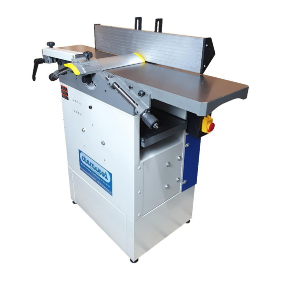
- Page 10 Using the Planer Thicknesser Feed Direction PLANING MODE Side Fence Outfeed Table Bridge Guard Angle Lock Bridge Guard Position Lock Planing Depth Scale Infeed Table Planing Depth Adjuster On / Off Switch Adjustable Feet THICKNESSING MODE Feed Direction Infeed Table Lock Dust Hose Connection Outfeed Table Lock Cutter Guard...
-
Page 11: Switching Modes
PLANING MODE With the machine set up in planing mode: Use the Bridge Guard Angle Lock to adjust the height of the Bridge Guard, so that the work piece can fit underneath. Set the Planing Depth Adjuster to the desired setting, reading off the Planing Depth Scale. If in doubt set the depth to 0.5mm Connect a dust extractor to the 100mm diameter outlet. -
Page 12: General Method
General Method When faced with a rough sawn piece of timber which requires planning on all 4 sides and taking down to a specific finished dimension, follow this guide: • Set the machine up for planning. • Identify the flattest of the two wider faces on the timber. (Face 1 on diagram) •... - Page 13 Knife Removal and Replacement If you are using the optional knife setting jig, please read those instructions first. Cross Section Of Cutter Block Locking Bar Square Head Bolt Knife Spring Setting Tool Each knife is held in place by a locking bar.
-
Page 14: Troubleshooting
Use the 7mm spanner provided to turn the bolts in a direction that winds them deeper into the locking bar. Continue until the knife can be removed. Fit the new or reground knife into the cutter block. Note the direction of the beveled cutting edge and ensure the new knife is installed the correct way around. -
Page 15: Declaration Of Conformity For Ce Marking
Excess Vibration Planing knives out of balance Reset the height of the knives Declaration of Conformity for CE Marking Charnwood Declare that Woodworking Planer & Thicknesser, Model W583 Conforms with the following Directives: Machinery Directive 2006/42/EC EMC Directive 2014/30/EU Conforms with the following UK Regulations:... - Page 16 Charnwood W583 Parts Diagrams A: STAND ASSEMBLY STAND ASSEMBLY CODE DESCRIPTION NO. CODE DESCRIPTION M06-2 Lower stand A02 GB6170- Hex nut M6 Washerφ6 GB97.1-85 A04 GB5783- Hex bolt M6X16 GB5783-86 Hex bolt M6X20 A06 GB6170- Hex nut M8 M0607 Motor...
- Page 17 KJD12 Switch A22 GB819-85 Screw M5X10 WDKG Inching switch A24 JTKG Emergency switch Washer φ6 GB818-85 Screw M6X16 A26 GB97.1-85 M0601 Protective cover B: LOWER STAND ASSEMBLY LOWER STAND ASSEMBLY DESCRIPTION DESCRIPTION CODE CODE GB5783-86 Hex bolt M6X16 B02 M0610 Lower leg GB97.1-85 Washerφ6...
- Page 18 C: THICKNESSING TABLE ASSEMBLY...
- Page 19 THICKNESSING TABLE ASSEMBLY CODE DESCRIPTION CODE DESCRIPTION C01 M0716 Nylon bush C02 GB818-85 Screw M4X6 C03 M12 Depth scale C04 M0715-1 Handle C05 M0715-2 Hand wheel C06 GB6170-86 Hex nut M8 C07 M0710 Plate C08 M0713 Shaft C09 M0703 Adjusting bar C10 M0711.1 Locking bar C11 M0718...
- Page 20 D: PLANER TABLE ASSEMBLY PLANER TABLE ASSEMBLY CODE DESCRIPTION CODE DESCRIPTION GB5783-86 Hex bolt D02 GB6170-86 Hex nut M5 M5X25 M081213 Spring D04 M081205-1 Limited pole “E” ringφ6 GB896-86 D06 GB70-85 Socket cap screw M6X20 M081202 Left bracket D08 NCM Socket countersunk screw M6X10 GB77-85...
- Page 21 GB5783-86 Hex bolt D12 GB6170-86 Hex nut M6 M10X50 GB5783-86 Hex bolt D14 GB70-85 Socket cap screw M6X25 M8X16 GB97.1-85 Washerφ8 D16 GB119-86 Pin 6X16 M1102 Locking block D18 M1101 Outfeed table GB6170-86 Hex nut M12 D20 M1011 Adjusting wheel M1006 Adjusting axle D22 GB5783-86...
- Page 22 E: CUTTER BLOCK ASSEMBLEY CUTTER BLOCK ASSEMBLY CODE DESCRIPTION CODE DESCRIPTION M081207.3 Square toes bolt E02 M081207.2 Blade locking block M081207.5 Blade E04 M081207.4 Spring M081207.1 Cutter block...
- Page 23 F: CLUTCH ASSEMBLY CLUTCH ASSEMBLY CODE DESCRIPTION CODE DESCRIPTION Washer φ6 GB5783-86 Hex bolt M6X10 F02 GB97.1-85 GB6170-86 Hex nut M10 F04 M082218 Pull spring GB93-87 Spring washer F06 M082202 plate φ10 GB97.1-85 washerφ10 F08 GB/T276-94 Bearing 80303 M082217 Pin axle F10 M082205 Sprocket M082201...
- Page 24 M082216 Short pin F30 M082206 Control handle GB818-85 Screw M5X8 F32 M082210 Sprocket M082210.1 Sprocket plate F34 GB77-85 Set screw M6X8 GB1096-79 Key 5X16 F36 GB818-85 Screw M5X16 GB6170-86 Hex nut M5 F38 GB6170-86 Hex nut M6 GB80-85 Set screw F40 M082219 Handle M6X20...
- Page 25 J: FENCE ASSEMBLY FENCE ASSEMBLY CODE DESCRIPTION CODE DESCRIPTION M1409 Guide rail M1411 Connecting plate GB70-85 Socket cap screw M1414 Locking handle M6X12 M1401 Left metal plate GB6170-86 Hex nut M5 GB5783-86 Hex bolt M5X40 M1407 Sliding plate GB867-86 Rivet 4X6 M1404 Bracket Washer φ10...
- Page 26 H: BRIDGE GUARD ASSEMBLY BRIDGE GUARD ASSEMBLY CODE DESCRIPTION CODE DESCRIPTION M1012.1 Locking pole H02 M1602 Rotor M1610 Sector plate H04 M1012 Locking handle M1603 Spring H06 GB96-85 Large washerφ6 M1605 Adjusting handle H08 M1609 Connecting pole M1611 Pin bolt H10 GB5783-86 Hex bolt M5X20 Spring washer φ5 GB93-87...
-
Page 27: Final Assembly
I: FINAL ASSEMBLY INAL ASSEMBLY CODE DESCRIPTION CODE DESCRIPTION Stand assembly M0822 Thicknesser clutch assembly Spring washer φ8 GB70-85 Socket cap screw GB93- M8X20 Thicknessing table Fence assembly assembly GB70-85 Socket cap screw GB818 Screw M4X6 M6X16 Infeed scale Infeed pointer GB818-85 Screw M4X6 Protective cover assembly... - Page 28 Last Updated February 2022 Charnwood, Cedar Court, Walker Road, Hilltop Industrial Estate, Bardon, Leicestershire, LE67 1TU Tel. 01530 516 926 Fax. 01530 516 929 email: sales@charnwood.net website: www.charnwood.net...
Need help?
Do you have a question about the W583 and is the answer not in the manual?
Questions and answers