
Subscribe to Our Youtube Channel
Related Manuals for Idex TREBOR INLINE DI


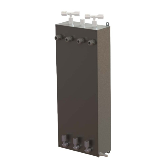
Summary of Contents for Idex TREBOR INLINE DI
- Page 1 INLINE DI HEATER Operation / Maintenance Manual SERIAL NUMBER: 8/16/2018 – MID PATENTS: U.S. 5971402, U.S. 6433319, U.S. 6479094B2, U.S. 6544583B2, U.S. 6580061B2, U.S. 6663914, U.S 6674053B2; ADDITIONAL PATENTS PENDING...
-
Page 2: Table Of Contents
CONTENTS INTRODUCTION ......................3 INTENDED USE AND AUDIENCE..............4 HEATER SIZING ....................4 SAFETY ........................6 SAFETY PRECAUTIONS ................... 6 2.1.a General Safety ..................6 SAFETY MESSAGE CONVENTIONS ............... 7 2.2.a Caution ....................7 2.2.b Warning ....................7 2.2.c Danger ....................7 HEATER INTERLOCKS .................. -
Page 3: Introduction
INTRODUCTION Inline DI Heater - The Smart Choice! Trebor’s ID quartz inline DI water heater provides the ultra-high purity you demand, with the reliability you expect. The ID heater’s flow path is smooth, free of particle traps and constructed entirely of GE 214 quartz, PTFE and PFA. -
Page 4: Intended Use And Audience
INTENDED USE AND AUDIENCE The ID heater is designed to safely heat DI water up to 100°C. The ID heater is not intended for use with combustible or flammable chemistries, such as solvents, or chemistries such as HF or KOH with accelerated quartz etch rates. This manual only covers the Trebor ID heater and heater accessories provided by Trebor. - Page 5 Figure 1-1 ��. ���� × (. ������ × ������ × ∆°��) = ���� ���������������� Sizing Formula: Conversions: ������ ������ = ��.�� �� × ( ∆°�� − ���� ) ∆°�� �� INLINE CHEMICAL HEATER OPERATION / MAINTENANCE MANUAL PAGE 5...
-
Page 6: Safety
SAFETY SAFETY PRECAUTIONS This section provides important information for safe operation of the ID heater. The equipment described in this manual uses hazardous voltage that can be dangerous. Local policies and procedures for safely operating any Trebor chemical heater(s) supersede the safety considerations listed below. It is the responsibility of all personnel to follow such policies and procedures. -
Page 7: Safety Message Conventions
SAFETY MESSAGE CONVENTIONS 2.2.a Caution Caution A Caution message indicates a potentially hazardous situation, which, if not avoided, could result in minor or moderate injury. It may also be used to alert against unsafe practices. A typical Caution message: Corrosive Chemical Product may contain hazardous corrosive liquids. -
Page 8: Element Over-Temperature Protection
An integrated magnetic reed switch allows a non-intrusive method for verification of sensor operation. Pass a strong magnet around the bottom of the heater just out from the drain plug to engage the reed switch and trigger the leak sensor see Figure 2-1. If magnet is not strong enough, remove the drain plug and move magnet into drain hole for testing. -
Page 9: Internal Over-Temperature Protection
= 236.6°C (Maximum allowable element temperature) Example 2: Given a maximum allowable liquid temperature of 140°C, a heater rated at 6 kW and a 75% duty cycle, the maximum element temperature limit is: = 140°C + (6)*(0.75)*(16.1) = 212.5°C (Maximum allowable element temperature) 2.3.d Internal Over-Temperature Protection The Trebor ID heater is supplied with a temperature sensor(s) located near the top of the quartz substrate. -
Page 10: Installation
INSTALLATION Ensure that all heater interlock and safety devices are functional prior to operation (refer to Section 2, Safety Requirements). Before starting the system, it is important to read and understand Section 4, Operation. Only trained, qualified, authorized personnel should operate this heater. Use 3/8”... - Page 11 Figure 3-2 INLINE CHEMICAL HEATER OPERATION / MAINTENANCE MANUAL PAGE 11...
-
Page 12: Utility Requirements
UTILITY REQUIREMENTS Utility CHEMICAL Heater System Power: 3kW 208 Vac 50/60 Hz, 1Ø, 20 Amp Service 4kW 208 Vac 50/60 Hz, 1Ø, 25 Amp Service 4kW 240 Vac 50/60 Hz, 1Ø, 25 Amp Service 4kW 400 Vac 50/60 Hz, 1Ø, 15 Amp Service ... -
Page 13: Liquid Drain
3.4.b Liquid Drain A housing drain plug is located at the bottom of the heater to drain off any liquid that may be present inside the housing, see Figure 3-1. ELECTRICAL CONNECTIONS Connection of required electrical hook-ups is required between the heater and control system. -
Page 14: Operation
OPERATION GENERAL Ensure that all heater interlock and safety devices are functional prior to operation (refer to Section 2, Safety Requirements). The ID heater is designed to heat DI water in either single pass (trim) or recirculation applications up to 100°C (minimum flow of 2lpm for IDA configuration). -
Page 15: Temperature Control
Allow the liquid to run through the system approximately 2 minutes prior to energizing the heater. TEMPERATURE CONTROL An external control system is required for operating the ID heater; see Figure 4-2 for a typical control set up. The system should consist of: temperature control system, interlock controls (see Section 2.3), and outlet liquid temperature sensor(s). - Page 16 Note: The user is responsible for providing an EMO circuit to interlock their entire system. This device can also be used to disengage heater power. PAGE 16 INLINE CHEMICAL HEATER OPERATION / MAINTENANCE MANUAL...
-
Page 17: Maintenance
MAINTENANCE SPARE PARTS There are no spare parts for the IC heater. PREVENTIVE MAINTENANCE SCHEDULE The IC heater requires no preventive maintenance. REMOVAL AND REPLACEMENT INSTRUCTIONS 5.3.a Heater Replacement The IC heater has been designed for quick replacement to minimize downtime and field service requirements. -
Page 18: Troubleshooting
TROUBLESHOOTING The following is an outline of routine troubleshooting techniques. For conditions not covered in this section consult Trebor or a factory authorized representative. IRREGULAR TEMPERATURE CONTROL SYMPTOM CAUSES SOLUTIONS Poor Temperature Control Low liquid flow Increase flow. Location of outlet Relocate outlet temperature sensor temperature sensor... -
Page 19: Interlock Sensors
INTERLOCK SENSORS ALARM CAUSES SOLUTIONS Liquid Leak Liquid leak detected inside If liquid is present in the heater housing housing, decommission and replace heater per Sensor/wiring shorted or Section 5.3. improperly wired to interlock Inspect/test sensor wiring. Element Over- No liquid or insufficient Increase flow rate. -
Page 20: Wiring Schematic
WIRING SCHEMATIC Heater Power Wiring ( IDA04V208 B08AA 1Ø Power 3Ø Power (Option S) (Option D or Y) Wire Color Description Wire Color Description Black Power Black Power Black Power Black Power Green Ground Black Power White Neutral (Y Only) Green Ground ... - Page 21 Heater Wiring Schematic: Figure 7-1 INLINE CHEMICAL HEATER OPERATION / MAINTENANCE MANUAL PAGE 21...
-
Page 22: Options
OPTIONS FLUID CONNECTIONS ( IDA04V208S ¼” Flare (Option F04) ½” Flare (Option F08) ¾” Flare (Option F12) ¼” Super 300 Pillar® (Option X04) ½” Super 300 Pillar® (Option X08) ¾” Super 300 Pillar® (Option X12) Super 300 Type Pillar®... -
Page 23: Warranty And Exclusions
WARRANTY AND EXCLUSIONS See the Trebor Standard Limited Warranty at www.idex-hs.com/support/trebor/downloads/TreborStandardLimitedWarranty_02-07.pdf INLINE CHEMICAL HEATER OPERATION / MAINTENANCE MANUAL PAGE 23... -
Page 24: Contact Information
10 CONTACT INFORMATION 10.1 GENERAL CONTACT INFORMATION Web: www.treborintl.com Phone Number: (801) 561-0303 Toll Free Number: (800) 669-1303 Fax Number: (801) 255-2312 Email: treborinfo@idexcorp.com treborsales@idexcorp.com Address: Trebor International 8100 South 1300 West West Jordan, Utah 84088 U.S.A. 10.2 TECHNICAL SUPPORT Email: treborservice@idexcorp.com Phone Number:...
Need help?
Do you have a question about the TREBOR INLINE DI and is the answer not in the manual?
Questions and answers