Table of Contents
Advertisement
®
Installation, Operation and Maintenance Manual
Please read and save these instructions. Read carefully before attempting to assemble, install, operate or maintain the
product described. Protect yourself and others by observing all safety information. Failure to comply with instructions
could result in personal injury and/or property damage! Retain instructions for future reference.
Models: PVe-20
PVe-35
PVe-45
PVe-55
General Safety Information
Only qualified personnel should install this system.
Personnel should have a clear understanding of these
instructions and should be aware of general safety
precautions. Improper installation can result in electric
shock, possible injury due to coming in contact with
moving parts, as well as other potential hazards.
Other considerations may be required if high winds
or seismic activity are present. If more information
is needed, contact a licensed professional engineer
before moving forward.
DANGER
Always disconnect power before working on or near
this equipment. Lock and tag the disconnect switch
or breaker to prevent accidental power up.
CAUTION
When servicing the unit, the internal components
may be hot enough to cause pain or injury. Allow
time for cooling before servicing.
CAUTION
Precaution should be taken in explosive
atmospheres.
1
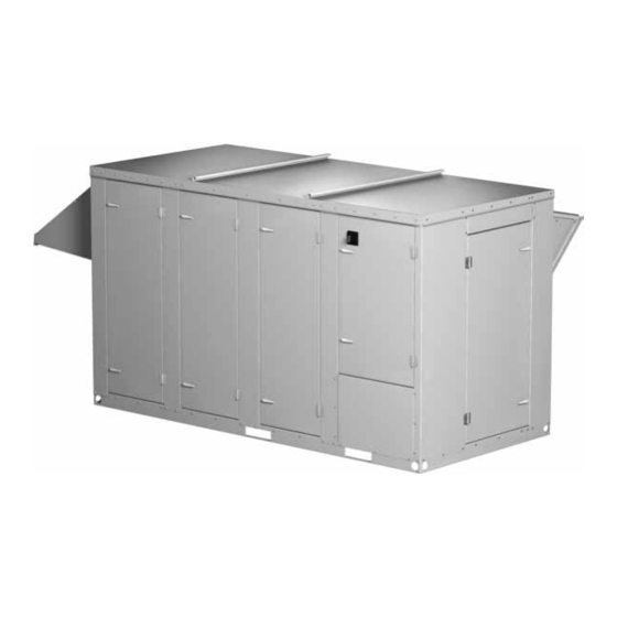
Model PVe Heat Recovery Unit
Heat Recovery Ventilators
1. Follow all local electrical and safety codes, as well
as the National Electrical Code (NEC), the National
Fire Protection Agency (NFPA), where applicable.
Follow the Canadian Electric Code (CEC) in
Canada.
2. All moving parts must be free to rotate without
striking or rubbing any stationary objects.
3. Unit must be securely and adequately grounded.
4. Do not spin fan wheel faster than maximum
cataloged fan RPM. Adjustments to fan speed
significantly affects motor load. If the fan RPM is
changed, the motor current should be checked to
make sure it is not exceeding the motor nameplate
amps.
5. Do not allow the power cable to kink or come in
contact with oil, grease, hot surfaces or chemicals.
Replace cord immediately if damaged.
6. Verify that the power source is compatible with the
equipment.
7. Never open access doors to the unit while it is
running.
Part #472846
Advertisement
Table of Contents
Troubleshooting

Related Manuals for Greenheck PVE-20


Summary of Contents for Greenheck PVE-20
-
Page 1: General Safety Information
Please read and save these instructions. Read carefully before attempting to assemble, install, operate or maintain the product described. Protect yourself and others by observing all safety information. Failure to comply with instructions could result in personal injury and/or property damage! Retain instructions for future reference. Models: PVe-20 PVe-35 PVe-45... -
Page 2: Zone
Traffic Department. If damaged upon arrival, file claim with carrier. Any physical damage to the unit after acceptance is not the responsibility of Greenheck Fan Corporation. Unpacking Verify that all required parts and the correct quantity of each item have been received. -
Page 3: Table Of Contents
Table of Contents Heating Coil Basic Operation ....3 Cooling Installation Coil Supplemental Installation, Operation and Maintenance Manuals ... 3 Installation . -
Page 4: Installation Stages
Lifting with a Forklift Unit base rail includes forklift lifting locations. Use weights shown to determine forklift size requirements. Unit Weights (lbs.) Approx. Model Weight PVe-20 1300 PVe-35 1600 PVe-45 2100 PVe-55 2700... -
Page 5: Service Clearances
Air Hood Bypass Damper Face Plate Heat Damper Exchanger SA Discharge Control Center OA Intake RA Intake Duct Dimensions Model 10.7 12.2 10.3 PVe-20 (280) (310) (270) 11.9 13.7 11.4 PVe-35 (310) (350) (290) 14.1 16.0 13.3 PVe-45 (360) (410) (340) 16.4... -
Page 6: Roof Curb Mounting
0.775 Dimensions are shown in inches. Curb Cap Details for Factory Supplied Roof Curbs Model PVe Heat Recovery Unit Curb Dimensions and Weights Unit Size PVe-20 PVe-35 PVe-45 PVe-55 All dimensions are shown in inches. Ductwork Connections Examples of poor and good fan-to- duct connections are shown below. -
Page 7: Rail Mounting / Layout
• Set unit on rails. Isometric view of PVe on rails Side view of PVe on rails Unit Size PVe-20 PVe-35 PVe-45 PVe-55 All dimensions are shown in inches. *Zones B and C identify regions/zones where rails may not be place due to ductwork. -
Page 8: Dimensional Data
Face Plate Heat Damper Exchanger Top view Outdoor Air Hood Plate Heat Exchanger Side view Unit Size Bypass Damper 104.1 59.7 41.5 PVe-20 (2650) (1520) (1060) Face Plate Heat Damper Exchanger 104.1 59.7 49.2 PVe-35 (2650) (1520) (1250) 110.6 59.7 61.1... -
Page 9: Electrical Information
Electrical Information The unit must be electrically grounded in accordance with the current National Electrical Code, ANSI/ NFPA 70. In Canada, use current CSA Standard C22.1, Canadian Electrical Code, Part 1. In addition, the installer should be aware of and comply with any local ordinances or electrical power company requirements that might apply. -
Page 10: Control Center Components
Typical Control Center Components 1. Main Disconnect (non-fusible, lockable) 2. Motor Starter 3. Motor Starter 4. Power Distribution Blocks 5. 24 VAC Control Transformer 6. 24 VAC Terminal Strip 7. Temperature Sensor with Override (used for Economizer Mode) 8. Dirty Filter Sensor 9. -
Page 11: Optional Accessories Frost Control Application/Operation
Optional Accessories Frost Control Application/Operation Cold climates, in combination with higher indoor humidity levels, may cause frost to form on the plate heat exchanger. To protect against the formation of frost, a temperature sensor is installed to measure the temperature of the air leaving the plates in the exhaust airstream. -
Page 12: Variable Frequency Drives And Wiring
Variable Frequency Drives for Energy Recovery Blowers Optional factory installed, wired, and programmed variable frequency drives (VFDs) may have been provided for modulating or multispeed control of the blowers. One VFD is provided for each blower (supply air and exhaust). The VFD’s provided are either Yaskawa model V1000 or J1000. Refer to the tables in this section for factory settings and field wiring requirements. - Page 13 Factory Set Points - continued Resetting the V1000 drive to factory defaults To reset the V1000 drive back to Greenheck factory defaults go to parameter A1-01 and set it to “2”. Then go to A1-03 and change it to “1110” and press enter.
-
Page 14: Typical Wiring Diagram
Typical Wiring Diagram Following is an example of a typical wiring diagram for the PVe. It is representative of circuitry that may be found in any PVe unit, but it is not intended to be unit-specific. Each PVe unit has a detailed wiring diagram located within the control panel. -
Page 15: Sensors And Lights
Dirty Filter Sensor Dirty filter sensors monitor pressure drop across the outdoor air filters, exhaust air filters or both. If the pressure drop across the filters exceeds the set point, the sensor will close a set of contacts in the unit control center. -
Page 16: Remote Control Panel And Wiring
Remote Control Panel and Wiring Schematics The remote panel is a series of junction boxes ganged together and includes a stainless steel faceplate. The remote panel is available with a number of different alarm lights and switches to control the unit. The remote panel ships loose and requires mounting and wiring in the field The remote panel is available with the following... -
Page 17: Sensors Mounted By Factory
Sensors Mounted by Factory Factory mounted temperature, pressure, and current sensors are available in the locations indicated on the unit diagram below. A list of available sensors is shown below. The specific sensors provided on a given unit are labeled in the unit control center on the terminal strip. Sensors are wired to the terminal strip to make it easy for the controls contractor to connect the Building Management System for monitoring purposes. -
Page 18: Start-Up
Qualified personnel should perform start-up to ensure safe and proper practices are followed. Unit Model Number _______________________________ (e.g. PVe-20) Unit Serial Number _______________________________ (e.g. 10111000) Start-Up Date _______________________________... -
Page 19: Optional Accessories
Optional Accessories Checklist Refer to the respective sections in this Installation, Operation and Maintenance Manual for detailed information. Refer to wiring diagram in unit control center to determine what electrical accessories were provided. Provided with Unit? Frost Control Application / Operation section: Frost Control set point Differential Timer... -
Page 20: Unit Start-Up, Fans
Unit Start-Up Refer to Parts List section for component locations. Fans The PVe models contain two forward curved (supply & exhaust) fans. These forward curved fans should be checked for free rotation. If any binding occurs, check for concealed damage and foreign objects in the fan housing. - Page 21 Vibration Excessive vibration may be experienced during initial start-up. Left unchecked, excessive vibration can cause a multitude of problems, including structural and/or component failure. The most common sources of vibration are listed. Many of these conditions can be discovered by careful observation.
-
Page 22: Overview
Maintenance Overview The Greenheck PVe Heat Recovery Ventilator is quite simply an interface unit that takes in outdoor air and either heats or cools that air and then delivers that air into the building HVAC system for further heating or cooling. -
Page 23: General
Routine Maintenance DANGER Electric shock hazard. Can cause injury or death. Before attempting to perform any service or maintenance, turn the electrical power to unit to OFF at disconnect switch(es). Unit may have multiple power supplies. CAUTION Use caution when removing access panels or other unit components, especially while standing on a ladder or other potentially unsteady base. -
Page 24: Fan Wheel And Fasteners
Series 400 or Farr 30/30 ® Model PVe Heat Recovery Unit Filter Size and Quantities Pleated Filter Size Unit Size Supply and Exhaust PVe-20 12 x 25 x 2 PVe-35 16 x 25 x 2 PVe-45 20 x 25 x 2 PVe-55 24 x 24 x 2 All dimensions in inches. -
Page 25: Parts List
Parts List 1. Supply blower • Forward curved fan • Adjustable motor mount for belt tensioning • Adjustable sheaves for speed control 2. Vibration isolators (quantity 4 per blower) • Neoprene 3. Aluminum plate heat exchanger 4. Supply weatherhood with 2-inch aluminum mesh filter 5. -
Page 26: Troubleshooting - Airflow
Troubleshooting – Airflow Test and Balance Report The Test and Balance Report (TAB) is utilized to determine whether the appropriate amount of outdoor air and exhaust air is being supplied and removed from a building, respectively. There are no set rules on what information must be included in a TAB report. -
Page 27: Troubleshooting - Unit
Troubleshooting – Unit Symptom Possible Cause Blown fuse or open circuit breaker. Defective motor or capacitor. Blower fails to Motor starter overloaded. operate Electrical. Drive. Control power (24 VAC) wiring run is too long (resistance should not exceed 0.75 ohms). Motor starters “chatter”... - Page 28 Troubleshooting – Unit Symptom Possible Cause One or both blowers turn off intermittently and Exhaust Only frost control sensors are tripping. back on after about 2 minutes Fan wheel rubbing on inlet. Bearings. Wheel out of balance. Loose wheel on shaft. Loose motor or blower sheave.
-
Page 29: Maintenance Log
Maintenance Log Date __________________ Time _____________ AM/PM Notes:___________________________________________ _________________________________________________ _________________________________________________ _________________________________________________ _________________________________________________ Date __________________ Time _____________ AM/PM Notes:___________________________________________ _________________________________________________ _________________________________________________ _________________________________________________ _________________________________________________ Date __________________ Time _____________ AM/PM Notes:___________________________________________ _________________________________________________ _________________________________________________ _________________________________________________ _________________________________________________ Date __________________ Time _____________ AM/PM Notes:___________________________________________ _________________________________________________ _________________________________________________ _________________________________________________ _________________________________________________ Date __________________ Time _____________ AM/PM... - Page 30 Maintenance Log Date __________________ Time _____________ AM/PM Notes:___________________________________________ _________________________________________________ _________________________________________________ _________________________________________________ _________________________________________________ Date __________________ Time _____________ AM/PM Notes:___________________________________________ _________________________________________________ _________________________________________________ _________________________________________________ _________________________________________________ Date __________________ Time _____________ AM/PM Notes:___________________________________________ _________________________________________________ _________________________________________________ _________________________________________________ _________________________________________________ Date __________________ Time _____________ AM/PM Notes:___________________________________________ _________________________________________________ _________________________________________________ _________________________________________________ _________________________________________________ Date __________________ Time _____________ AM/PM...
- Page 31 Maintenance Log Date __________________ Time _____________ AM/PM Notes:___________________________________________ _________________________________________________ _________________________________________________ _________________________________________________ _________________________________________________ Date __________________ Time _____________ AM/PM Notes:___________________________________________ _________________________________________________ _________________________________________________ _________________________________________________ _________________________________________________ Date __________________ Time _____________ AM/PM Notes:___________________________________________ _________________________________________________ _________________________________________________ _________________________________________________ _________________________________________________ Date __________________ Time _____________ AM/PM Notes:___________________________________________ _________________________________________________ _________________________________________________ _________________________________________________ _________________________________________________ Date __________________ Time _____________ AM/PM...
-
Page 32: Warranty
472846 • Model PVe IOM, Rev. 1, October 2009 AMCA Publication 410-96, Safety Practices for Users and Installers of Industrial and Commercial Fans, provides additional safety information. This publication can be obtained from AMCA International, Inc. at: www.amca.org. Copyright 2009 © Greenheck Fan Corp.
Need help?
Do you have a question about the PVE-20 and is the answer not in the manual?
Questions and answers