Table of Contents
Advertisement
Quick Links
MC200-5AM Analog I/O Module
User Manual
To reduce the chance of accident, please carefully read the operation
instructions and notes in this book prior to use. Only adequately trained
personnel shall install or operate this product. Strict compliance with the
safety rules in relevant industries, the operation instructions and safety
precautions provided in this book is required in equipment operation.
1 Port Description
1.1 Port
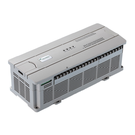
The extension port and user port of MC200-5AM are both protected by a
cover, as shown in Figure 1-1. Removing the covers reveals the extension
port and user port, as shown in Figure 1-2.
Extension port cover
User port cover
Extension cable
Figure 1-1 MC200-5AM appearance
The extension cable connects MC200-5AM to the system, while the
extension port connects MC200-5AM to another extension module of the
system. For details on connection, See 1.2 Connecting Into System.
The user port of MC200-5AM is described in Table 1-1.
Table 1-1 MC200-5AM user port description
Terminal Name
Description
Analog power supply
1
24V+
24V+
Analog power supply
2
24V-
24V-
3
FG Shielding ground
4
PG Protection ground
5
V1+ CH 1 voltage input
6
I1+ CH 1 current input
7
VI1- CH1 commond GND
8
V2+ CH2 voltage input
9
VI2- CH2 commnd GND
10
I2+ CH2 current input
Note: An input channel cannot receive both voltage signals and current
signals at the same time. If you intend to use a channel for current
measurement, short its voltage input terminal and current input terminal.
1.2 Connecting Into System
Through the extension cable, you can connect MC200-5AM to MC200 series
basic module or other extension modules. While through the extension port,
you can connect other MC200 series extension modules to MC200-5AM. See
Figure 1-3.
Removing extension port cover
before connection
Basic module
Extension cable
Figure 1-3 Connecting into system
1.3 Wiring
Figure 1-4 shows the wiring of the user port.
Extension port
User port
2
26
25
2
4
6
8
10
12
14
16
18
20
1
3
5
7
9
11
13
15
17
19
24V-
I 1+
V2+
I2+
I3+
V4+
I4+ VO + IO+
24V+ FG
V1+
VI1-
VI2-
V3+
VI3-
VI4-
VIO-
EC
- 5 AM
20
Extension cable
Figure 1-2 Module ports
Terminal Name Description
11
V3+ CH3 voltage input
12
I3+ CH3 current input
13
VI3- CH3 common GND
14
V4+ CH4 voltage input
15
VI4- CH4 common GND
16
I4+ CH4 current input
17
· NC
18
VO+ Voltage output
Output channel
19
VIO-
common GND
20
IO+ Current output
Extension module
Load
②
①
④
Voltage input
①
AGND
Current input
①
AGND
⑧
Figure 1-4 Wiring of MC200-5AM user port
The circled 1 ~ 9 stands for the nine points to be observed during wiring.
1. It is recommended to use shielded twisted pair for the analog input and
output and separate them from power cables and any cable that may
generate EMI.
2. If the I/O signal has electric noise or voltage fluctuation, it is advisable to
connect a smoothing capacitor (0.1µF ~ 0.47µF/25V).
3. If strong EMI exists, connect the FG terminal to the PG terminal.
4. Each load of the PLC should be grounded separately.
5. If a channel is used for current input, short its voltage input terminal and
current input terminal.
6. Shorting the voltage output terminals or connecting current load to voltage
output terminals may damage MC200-5AM.
7. Properly ground the module's PG terminal.
8. The basic module's 24Vdc auxiliary power or other qualified external
power supply can be used as the power source of the module's analog
circuit.
9. Do not use the NC terminal.
2 Indices
2.1 Power Supply
Table 2-1 Power supply
Item
24Vdc (-15%~20%), maximum allowable ripple voltage
Analog circuit
5%, 90mA (from basic module or external power supply)
Digital circuit
5Vdc, 50mA (from basic module)
2.2 Performance
Table 2-2 Performance
Item
15ms/channel (normal)
Conversion
AD conversion
8ms/channel (high speed)
speed
DA conversion 6ms/channel (max.)
-10 ~ 10Vdc (input impedance 200kΩ)
Warning: this module may be damaged if
Voltage
Analog
the input voltage exceeds ±15Vdc
input
-20~20mA (input impedance 250Ω)
Current
Warning: this module may be damaged if
the input current exceeds ±32mA
Analog
Voltage
-10~10Vdc (external load impedance ≥ 2kΩ)
output
Current
0~20mA (external load impedance ≤ 520Ω)
Default: -2000 ~ 2000
Digital output
Setting range: -10000 ~ 10000
Default: -2000 ~ 2000
Digital input
Setting range: -10000 ~ 10000
Voltage input
5mV
Current input
10µA
Resolution
Voltage output
5mV
Current output
10µA
Analog input
±1% of full range
Accuracy
Analog output
±1% of full range
VO +
IO+
⑥
VIO -
AGND
⑨
390
K
V4+
130
K
I4+
②
AGND
CH4
VI 4-
250
130
K
FG
390
K
390
K
V1+
130
K
I1+
②
⑤
AGND
CH1
VI 1-
250
130
K
FG
390
K
③
24 V+
5 V
+
DC /DC
AGND
⑦
converter
24 V-
5 V
-
EC
5AM
-
20
Description
Index
CHO
1
Advertisement
Table of Contents

Related Manuals for Megmeet MC200-5AM

Summary of Contents for Megmeet MC200-5AM
- Page 1 24 V- 1.1 Port The extension port and user port of MC200-5AM are both protected by a Figure 1-4 Wiring of MC200-5AM user port cover, as shown in Figure 1-1. Removing the covers reveals the extension The circled 1 ~ 9 stands for the nine points to be observed during wiring.
- Page 2 DA conversion input data. It uses FROM command to 1. Digital output after AD conversion read AD conversion result and other data from the BFM of MC200-5AM. b10: digital outside the range of -2048 ~ 2047;...
- Page 3 A0, and D1 is the channel’s digital input corresponding to analog output A1. 13. BFM#4095: module ID. ID of MC200-5AM is 0x3142. The user program in PLC can use this ID to identify the module before transceiving data.
- Page 4 1. Check that the wiring of analog input meets the requirements (see 1.3 wiring). 2. Check that the extension cable of MC200-5AM is properly inserted in the extension port. 3. Check that the 5V and 24V power supplies are not overloaded. Note: The digital circuit is powered by the basic module through extension cable.
Need help?
Do you have a question about the MC200-5AM and is the answer not in the manual?
Questions and answers