Table of Contents
Advertisement
Quick Links
Advertisement
Table of Contents

Subscribe to Our Youtube Channel
Related Manuals for BT Redcare Ultimate

Summary of Contents for BT Redcare Ultimate
- Page 1 Ultimate Installation Guide EN 50136-2: 2013 EN 50131-10: 2014 Cert No. 1270g...
-
Page 2: Table Of Contents
Contents Introduction Diagnostics Restore defaults Product description Web server Specifications Main status display Safety notes Status Mounting and wiring System messages Status Removal of cover Network Mounting GPIO Connection terminals Name editor xDSL connections Keyswitch WAN connections Reports LAN connections Defaults Power connections Logout... -
Page 3: Introduction
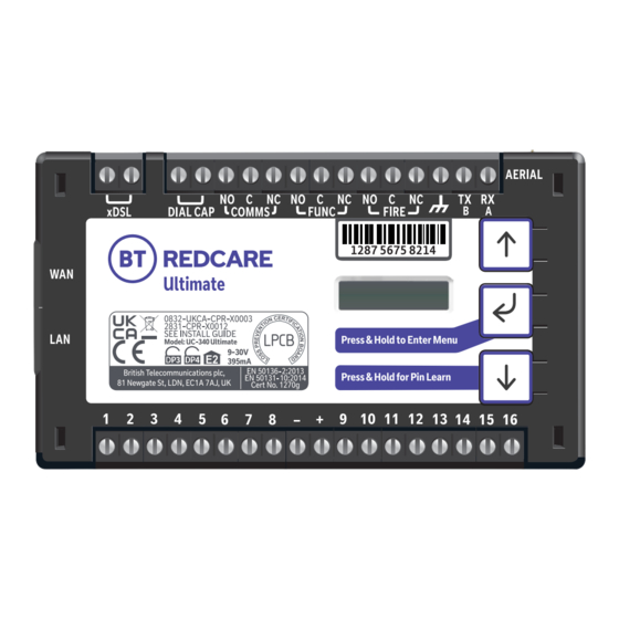
Figure 1 – Ultimate unit (not to scale) Ultimate is a dual path alarm signalling unit with its own built in hub. It is set up to work with private broadband service for transmitting alarm signals from a customer’s alarm panel, via the BT Redcare private network, to an Alarm Receiving Centre (ARC) using pass-through mode of operation. -
Page 4: Specifications
Primary path fail reporting 90 secs Secondary path fail reporting 60 mins Both paths fail concurrent 3 mins Catastrophic failure (both paths together) 3 mins Alarm Transmission category EN Standards / PD6669 (UK) PD6669, EN50131 (2017) Grade Grade option (Table 10 EN50131-1 2020) Previous grade (Pre June 1st 2019) Environmental class Information and Substitution security... -
Page 5: Safety Notes
Safety notes Warning: Read all safety warnings and instructions. Failure to heed warnings and follow instructions may result in electric shock, fire risk and/or personal injury. Work area safety • Keep work area clean, well lit and free of obstacles. •... -
Page 6: Mounting And Wiring
EN 50131-1. For Grade 4 intrusion alarm systems the Ultimate SPT must be located within the intrusion alarm panel enclosure. Alternatively, the Ultimate SPT can be housed within a separate enclosure meeting the applicable protection requirements of EN 50131-10 and that is directly coupled to the intrusion alarm panel enclosure. -
Page 7: Connection Terminals
Connection terminals All screw terminals are suitable for use with a standard 3mm blade terminal screwdriver. xDSL connections Connection to the DSL service is by the two screw connections top left of the unit labelled xDSL. When the xDSL connection is used, pass the cable through the supplied ferrite twice (two turns), using the minimum wire length around the ferrite. -
Page 8: Alarm Inputs
Alarm inputs The unit has 16 alarm inputs which are presented on screw terminals along the bottom of the unit. These are labelled as Pin 1–8 and 9 –16. By default the 16 alarm inputs require a positive condition to be presented to send an alarm. -
Page 9: Outputs
The aerial should be installed a distance of 20cm or greater away from any user or bystander. Carry out a survey to establish the best location. If necessary, a selection of high gain and extension aerials can be purchased from the BT Redcare shop at btinstallershop.com... -
Page 10: Programming
Programming Unit initialisation The unit will immediately attempt to connect to the BT Redcare platform over the configured paths. The unit will typically complete path establishment in the following times from power up. The xDSL/FTTP Path takes longer as the DSL modem needs to train up with the broadband service. -
Page 11: Signal Strength
Signal strength That is: That is: • On 2G below -90dBm = X will be displayed • On 4G below -120dBm = X will be displayed • On 2G between -90 and -85, 1 bars will • On 4G between -120 and -110, 1 bars will be displayed be displayed •... -
Page 12: Pin Inputs
PIN inputs Of the 16 alarm pin inputs, all behave as general purposes inputs with the following exceptions: • Pin 1 must be used for Fire alarm when ACK condition needs to elapse before transmission. NAK outputs are used for Fire panels. The Similarly, restoring pin 13 will immediately signalling unit, when configured, provides an remove pin 13 from the display, but 7 minutes... - Page 13 1s. When the acknowledgement is received in less than 1 second after pin 4 is triggered then To ensure that Ultimate can inform the fire alarm the output will remain operational for 1s. panel of status as per the requirements of EN 54, Fire NAK output: the outputs need to be configured as follows.
-
Page 14: Configuration
Configuration Pin Learn For speed of installation a single button press Pin Learn is available. All pins to be used should be wired in and all the pins should be in the Press & Hold for Pin Learn non alarm state. No tampers should be active (if wired in) and Pin 4 (open/close) should represent the system being set/closed. -
Page 15: Button Configuration
Button configuration The button configuration mode is entered by holding down the centre configuration button (Enter) for 3s. The unit will then display configuration. Configuration Press the Enter button again and the display will show the first menu option. Inputs Inputs When in the main menu, each press of will step to the next menu item down. -
Page 16: Main Menu Display
Main menu display Version Exit Configuration Serial Panel Restore Inputs Output Type Network Diagnostics Back Type Defaults Output Type 1 xDSL/FTTP Pin Learn Output Type 2 ETH Method Panel Type Web Server Input Sense Output Type 3 Tunnel Port Back Back Inputs EOL Keyswitch... -
Page 17: Input Sense
Input Sense The polarity of the pins can manually be configured by the installer. This is additional to the Pin Learn function described earlier. Example – to configure pin 4 to be positive removed: Configuration Inputs Inputs Sense Pin Learn Press until Inputs Sense 4 Inputs Sense 1... -
Page 18: Inputs Eol
Inputs EOL The alarm inputs (PINS) can be set to the following modes: • None – (Alarm and Restore) • EOL (Single end of line mode) – (Alarm, Restore and Cut) • DEOL (Dual End of line mode) – (Alarm, Restore, Cut and Short) Example –... -
Page 19: Outputs
Outputs The three relay outputs can be configured as follows: 1. Output type 1 (Comms): • BSIA 175 Mode – operates when either path is in fault but in conjunction with Pin 11 ATS allows the panel to interrogate the device to determine a single or dual path fault (default). - Page 20 Example – configure Output 1 (Comms) for a single path fault Configuration Inputs Output Type Output Type 1 BSIA 175 Output Type 1 * Output Type 1 * Single Path Fault BSIA 175 Press and hold Notice – Saved! • Access the configuration menu by holding Enter button for 3 seconds, press the Enter button again, the display will show Pin Learn.
-
Page 21: Network
Network The programming options under the network sub menu are: 1. xDSL/FTTP Allows the unit to be changed between dynamic (DHCP client) or Static mode. Default setting is enabled. The Ethernet port will attempt to obtain an IP address from a DHCP server on the LAN. •... -
Page 22: Ethernet Mode
Ethernet Mode PPPoE Default it is set as PPPoE for connecting to the Redcare broadband service and should not be changed unless the device is being used temporarily on a customer network or broadband. If being used on a customer Network or Broadband service the unit can be set to DHCP or Static. This allows the unit to be changed between dynamic (DHCP client) or Static mode. -
Page 23: Setting A Static Ip, Netmask And Gateway Address
Setting a static IP Address, Netmask and Gateway Address If the unit is to be connected to a LAN that requires the unit to have a static IP address (e.g. no DHCP server on the LAN) then this can be configured as follows after setting DHCP to Disabled. - Page 24 Then use to step to gateway address and use the same process as above to set subnet address ETH Subnet Addr ETH GW Addr 255.255.255.15 0.0.0.0 ETH GW Addr * ETH GW Addr * 0 0.000.000.000 00.000.000.000 Press until correct number First digit highlighted Press to get to next digit...
-
Page 25: Tunnel Port
Where this is the case then the unit can be configured to use the alternative port 10443. The BT Redcare servers are set to accept both ports and so no changes are required other than on the unit’s configuration. -
Page 26: Web Passcode
Web passcode This code is used to set up both the installer and customer app. The passcode will need to be entered by you and can be any 8 digits. Configur Configuration Inputs Network xDSL / FTTP FTTP (WAN) Press until shows Web Passcode Web Passcode* Use enter, up and... -
Page 27: Serial Connection Panel Type
Serial connection panel type This menu selects the panel connection type for serial connected panels (RS232 or RS485). Settings: • Galaxy Classic 485 H (Classic 500/504/512 (RS485)) • None • Texecom 816 (Texecom 412/816/832 (RS232 • Dimension GD 232 (Galaxy Dimension 19200 8n2 inv)) 48/96/264/520 (RS232 9600 8n1)) •... -
Page 28: Diagnostics
Press and hold Notice – Saved! You will then need to plug in your laptop and login to the device. Open your web browser and enter http://192.168.33.1 You can get the username and password from your BT Redcare account manager. -
Page 29: Restore Defaults
The unit will now have a static IP address of 192.168.33.1 for the duration that the web console is enabled. To access the Web Server a PC needs to be connected to the Ethernet port. • Web Server will automatically exit after 20 minutes. •... -
Page 30: Web Server
Web server Log in with the BT username = xxxxx, password = xxxxxxxx This is available from the BT Redcare Technical Helpdesk or your Redcare account manager. To comply with EN 50136-2 Clause 5.2 Access levels, the PIN code access must be set to 6-digits. -
Page 31: Status
Status These icons show the status of the signalling paths and if there are any outstanding alarms. Green for the signalling path icons indicates signalling paths are successfully connected to the platform. Red indicates that a path is down. The bell icon is green in the example on the previous page as we have no alarms showing in the system messages box, which you would expect to see as the system will be set. - Page 32 The below shows the most recent events. If you click on the drop down you are able to filter the events by type. e.g. Alarms, System, Configuration or Connection. In the event log on the app or on the unit web page ** indicates a non-reportable event.
- Page 33 The settings menu has sub menus to be able to program the unit. The first screen gives you details of the device including MAC address and firmware version. Use the down button to step to the first sub menu option or use the drop down to access the sub menus.
-
Page 34: Status
Status The status sub menu shows the status of the IP path. It also shows the mobile path status, if it’s using 2G or 4G, the signal strength, which SIM and operator. • 23410 – O2 • 23415 – Vodafone •... -
Page 35: Network
Network The Network menu allows you to change the broadband service type between Ethernet (FTTP), VDSL ( FTTC) and ADSL. When set to ADSL2 or VDSL2 no other changes should be made as this could affect the service operation. If you wish to use this unit temporarily as an Advanced unit on a customer network or broadband, then select Ethernet as the WAN interface and the... - Page 36 For ADSL and FTTP ( WAN) the settings are as follows. These should not be changed.
-
Page 37: Gpio
GPIO In this menu, by using the drop down arrows on each section, you can change any of the PIN input status from High (positive removed) to Low (positive removed). You can set up either end of line (EOL) or dual end of line (DEOL) for each PIN as required. Mains fail time for Pin 13 can be adjusted. - Page 38 Program success will be displayed. A keyswitch can be set up to operate in conjunction with the BT Redcare App. Any pin can be used, but will typically be Pin 4. It can be Latched or Momentary and armed low or high.
-
Page 39: Name Editor
Name editor It is possible to add names to the PIN inputs. This will then show up on the customer app and notifications. You can choose a description for the USER relay outputs. Click save when you have entered all the information. Allows selection of the Serial connection for specific panel types. -
Page 40: Keyswitch
Keyswitch Output pulse period can be changed if required. (milliseconds) There is an option to change the output mode to Latched. Reports Reports This allows you to set up a number of email addresses that could receive emails on the various options. e.g. Alarms and System messages. -
Page 41: Defaults
Defaults The above restores the unit to factory settings by clicking Reset to Defaults. Logout Clicking Logout will take you back to the sign in screen. Should the web server enablement time out, you will not be able to save changes. You will need to re-enable the Web Server through the programming buttons. -
Page 42: Interconnection Monitoring
12V or 24V supply input E0L resistor 2 Normally open contacts To pin input You will need 1 x 3K3 and 1 x 10K resistors for each PIN with interconnection monitoring. Resistors are available from the BT Redcare installer shop btinstallershop.com... -
Page 43: What Happens When Pins Are Configured And Wired In This Way
3.3KΩ 1% 10KΩ 1% brown, black, black, red, brown brown, black, black, red, brown Resistor Item Code Label Colour Code 089446 Red Dot in packet 089447 Blue Dot in packet What happens when pins are configured and wired in this way The dual resistor EOL mode is able to detect four states: •... -
Page 44: Example Configuration And Wiring For Connection To Fire Panel With Interconnection Monitoring
Example configuration and wiring for connection to fire panel with interconnection monitoring Ensure that the required pins have Dual EOL enabled in the config menu. In the example Pin 1 and Pin 8 have been enabled for this. Note it is available on pins 1 – 16 •... -
Page 45: Roaming Sims
Panel upload Download and Enhanced format signalling (SIA/CID) Remote access to the alarm panel can be achieved using the BT Redcare UDL facility. Additional panel set up information is also available for enhanced format signalling. Contact your BT Redcare representative for further details. -
Page 46: Connection Advice
Example below shows connection via RS 485 to a Galaxy Dimension panel: Figure 11 (not to scale) Connection advice The unit should be connected to the Honeywell Galaxy panel as shown in figure 11, RS485A to A1 and RS485B to B1. Do not use the secondary data line (if your panel has one –... -
Page 47: Alarm List
If intending to use dial capture or serial for sending alarms, please confirm beforehand with your ARC that their automation software is capable of differentiating correctly between PIN alarms (Ultimate or Redcare Platform generated alarms) and alarm panel generated ZONE alarms. -
Page 48: Disposal
The manufacturer is not liable for any purely economic loss arising from any use of this equipment. All responsibility and liability in the use of BT Redcare products are assumed by the user. -
Page 49: Glossary
Fibre To The Premise Transmit Greenwich Mean Time VDSL Very high speed digital subscriber line Internet Protocol Wide Area Network Local area Network Support For assistance with your BT Redcare installation, please contact the BT Redcare Helpdesk on: 0800 800 628. -
Page 50: Approvals
Cert No. 1270g Compliance to EN 50136-2: 2013 and EN 50131-10: 2014 EN50136, EN50131, PD6669, PD6662 Ultimate is suitable for use in systems installed to conform to PD 6662:2017 at Grade 4 (DP4) and environmental class 2. EN 54-21:2006 EN 54-21:2006... -
Page 51: Appendix 1
Appendix 1 For the purposes of on‑going maintenance and configuration Company name Authorises Installer company name Remote access to BT Redcare Next Generation Supervised Premises Transceiver Serial No. number Installed at: premises address Date Signature... - Page 52 Offices worldwide The services described in this publication are subject to availability and may be modified from time to time. Services and equipment are provided subject to British Telecommunications plc’s respective standard conditions of contract. Nothing in this publication forms any part of any contract. ©...
Need help?
Do you have a question about the Ultimate and is the answer not in the manual?
Questions and answers