Table of Contents
Advertisement
Quick Links
OWNERS INSTRUCTION
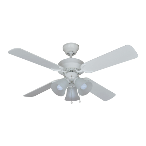
MONTANA
READ INSTRUCTIONS CAREFULLY FOR SAFE INSTALLATION AND
FAN OPERATION. IF UNSURE CONSULT
SUITABLE FOR 230V/50 CYCLE ELECTRICAL SUPPLY
Enquiries on installing your fan please call our help line on
technical@fantasiaceilingfans.com
MANUAL
106CM/42" or 91CM/36"
INSTALLATION
OPERATION
MAINTENANCE
CAUTION
A QUALIFIED ELECTRICIAN
1
01959-564440
Advertisement
Table of Contents

Related Manuals for EuroFans MONTANA


Summary of Contents for EuroFans MONTANA
- Page 1 OWNERS INSTRUCTION MANUAL 106CM/42” or 91CM/36” MONTANA INSTALLATION OPERATION MAINTENANCE CAUTION READ INSTRUCTIONS CAREFULLY FOR SAFE INSTALLATION AND FAN OPERATION. IF UNSURE CONSULT A QUALIFIED ELECTRICIAN SUITABLE FOR 230V/50 CYCLE ELECTRICAL SUPPLY Enquiries on installing your fan please call our help line on 01959-564440 technical@fantasiaceilingfans.com...
-
Page 2: Safety Precautions
Safety Precautions 1. To ensure the success of the installation be sure to read the instructions and study the diagrams thoroughly before commencing. 2. All electrical work should only be undertaken after disconnection of the power by removing fuses or turning off the circuit breaker to ensure all pole isolation of the electrical supply. -
Page 3: Supplied Parts
Supplied Parts One fan AC motor assembly One hanger bracket fitted with terminal block and top rubber washers. One set of blades One set of blade carriers One 3 llght llght kit One screw-pack with balancing kit One installation booklet. Tools and Materials Required Philips screwdriver Blade screwdriver... -
Page 4: Assembling And Hanging Your Ceiling Fan
ASSEMBLING AND HANGING YOUR CEILING FAN NOTE: Before installing ensure that you have all poles disconnection of the electricity supply and that you refer to qualified electrician to ensure that all wiring is carried out in accordance with I.E.E. Regulations, current good practice, national and local electrical codes. A. -
Page 5: Fan Checking
STEP 3 : LIGHT KIT INSTALLING Unscrew three screws from switch cover of light kit Connect the push plug for light kit of ceiling fan to push plug of light kit. Blue to Blue wire Orange to Orange arefully collect all wires into switch housing of ceiling fan, then install the light kit to switch housing using the 3 screws. -
Page 6: Flush Mount Style Assembly Diagrams
FLUSH MOUNT STYLE ASSEMBLY DIAGRAMS Fig.1 Fig.2 JOIST OR BEAM CEILING (MAYBE ATTACHED ON THE PLATE) MOUNTING PLATE ROUND STEEL WOOD SCREWS Fig.3 Fig.4... - Page 7 B. DROP ROD STYLE INSTALLATION STEP 1 : HANGER BRACKET INSTALLATION Secure the hanger bracket to joist with wood screws, rubber and steel washers. Please make sure it is secured firmly. (See Fig. 6)/page 7. CAUTION : Be sure that the mounting location can support load of at 70 kilos.
- Page 8 STEP 4 : LIGHT KIT INSTALLING Unscrew three screws from switch cover of light kit Connect the push plug for light kit of ceiling fan to push plug of light kit. Blue to Blue wire Orange to Orange wire Carefully collect all wires into switch housing of ceiling fan, then install the light kit to switch housing, using the three screws.
-
Page 9: Drop Rod Style Assembly Diagrams
DROP ROD STYLE ASSEMBLY DIAGRAMS Fig.5 Fig.6 Fig.7 Fig.8... -
Page 10: Wiring Instructions
WIRING INSTRUCTIONS NOTE: Before installation ensure that you have all pole disconnection of the electricity supply and that you refer to a qualified electrician to ensure that all wiring is carried out in accordance with I.E.E. Regulations current goods practice national and local electrical codes. Carefully read the wiring instructions and diagrams since improper installation may result in an electrical short and void the warranty. - Page 11 Assemble the light kit A. Connect the male and female plug between the light kit and fan. B. Install the light plate onto the switch housing using the screws provided. C. lnstall the light shades onto the fitter using the 3 thumb screws.
- Page 12 Operating instructions Having checked that all electrical connections are securely made and insulated, turn on the power and check the operation of the fan. The pull switch on the side of the motor housing is the selection switch for the speed function of the fan and is also the on/off function. The first pull from the off position takes you on to the high speed;...
-
Page 13: Blade Balancing
Blade balancing Whilst every precaution is taken at the factory to ensure your fan is of the highest quality, imbalance may occur. This may be due to slight irregularities in the blades or blade carriers. Further problems can be caused by deviating from these instructions. The following procedure may help to rectify the situation. -
Page 14: Ceiling Fan Warranty
Ceiling Fan Warranty. You must have the original purchase receipt or bill of sale to make a warranty claim. No claim will be accepted unless proof of date of purchase is available at the time of making the warranty claim. Ceiling Fan Warranty Period. - Page 15 106CM/42” or 91CM/36” MONTANA FANTASIA DISTRIBUTION LTD. Unit B. The Flyers Way, Westerham, Kent, TN16 1DE Tel : (01959) 564 440 Fax : (01959) 564 829 E-MAIL: info@fantasiaceilingfans.com...
- Page 17 106CM/42” or 91CM/36” MONTANA Please cut out this warranty page and send it in an envelope to the address below. Alternatively please go to our website www.fantasiaceilingfans.com and fill in the warranty section there. FANTASIA DISTRIBUTION LTD. Unit B. The Flyers Way, Westerham, Kent, TN16 1DE...
Need help?
Do you have a question about the MONTANA and is the answer not in the manual?
Questions and answers