Table of Contents
Advertisement
Quick Links
rev 2.14 / 2021 07 15
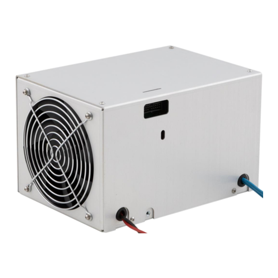
PCA-20 / PCA-25
capacitor charging modules
User manual
Warning! This equipment may be dangerous.
Please read the entire user manual carefully before using the product.
Important note. Module is sensitive to the reverse polarity applied to the
output. If you aren't sure in your application, please contact the manufacturer for
the details.
Advertisement
Table of Contents

Related Manuals for OEM PCA-20

Summary of Contents for OEM PCA-20
- Page 1 2.14 / 2021 07 15 PCA-20 / PCA-25 capacitor charging modules User manual Warning! This equipment may be dangerous. Please read the entire user manual carefully before using the product. Important note. Module is sensitive to the reverse polarity applied to the output.
-
Page 2: Table Of Contents
Table of content WARNINGS........................3 EXPLANATION OF SYMBOLS ..................3 OVERVIEW / DESCRIPTION ................... 4 COOLING........................4 APPEARANCE....................... 4 CONNECTORS / PINS / INTERFACE SIGNALS ..............5 INSTALLATION ......................8 OPERATIONS ....................... 8 FAULTS ........................8 SPECIFICATIONS ......................9 DIMENSIONAL DRAWING ................... 11 HOW TO ORDER?....................... -
Page 3: Warnings
Warnings Warning! The equipment is CLASS I ME EQUIPMENT. To avoid the risk of electrical shock, the equipment must be protectively grounded. Warning! The equipment should only be used inside the medical equipment, which has means to isolate its circuits electrically from the supply mains on all poles simultaneously. -
Page 4: Overview / Description
AC input to the regulated high voltage DC output to charge capacitors. Output power is 2000W and 2500W for PCA-20 and PCA-25 respectively. The maximum output voltage level (V ) could be choosen from 300V to 1500V at the moment of order. -
Page 5: Connectors / Pins / Interface Signals
Connectors / Pins / Interface signals INPUT: wires (2pcs) – AC input (110-240VAC 50/60Hz for PCA-20 and Blue 200-240VAC 50/60Hz for PCA-25) HV OUTPUT: wire – HV OUTPUT positive Black wire – HV OUTPUT negative Cable length warning Despite the lengths of all cables can be customized on request, we recommend to keep length of HV OUTPUT and INPUT cables as short as possible (max 30-50cm). - Page 6 INTERFACE: MOLEX 0901301120 PIN (color) DESIGNATION DESCRIPTION Module’s internal temperature test point. 1 (-) TEMP Test point By default the pin is unconnected, but can be activated on request. PINS 2,4,5,6 are connected to the circuit ground of all internal circuits. The return 2,4,5,6 (black) Ground signal connection for all interface signals...
- Page 7 The voltage at this pin is a signal proportional to the instantaneous output. 17 (violet) Voltage Monitor 0-10V corresponds to 0-V Current capability 1,5mA; R = 1kOhm This pin is pulled to ground when some failure occurs. In this case the high voltage output will be also disabled.
-
Page 8: Installation
• Use four M4 mounting holes on the bottom side of PCA-20 (PCA-25) for fixation of the module in your system. Refer to the Dimensional drawing section for their location. -
Page 9: Specifications
Specifications ELECTRICAL PCA-20 PCA-25 Input: 110-240VAC, 200-240VAC, Input voltage 50/60Hz 50/60Hz Input current <21A <15A Output: user selectable in the range of Maximum output voltage 300-1500V (at the moment of order, higher on request) Nominal output power 2000W 2500W (partial discharge modifications, can be achieved in regime 70-100% of , rated input voltage, 25 °C) - Page 10 Forced air (build in fan) Environment: +10… +40°C Operation temperature -20 … +60°C Storage temperature Humidity 90%, non-condensing PCA-20 can be used with 100-240VAC input until its average output power is limited with 1800W. MECHANICAL Dimensions see dimensional drawing below Weight approx 2.9kg...
-
Page 11: Dimensional Drawing
Dimensional drawing... -
Page 12: How To Order
How to order? PCA-20-XXXX-YY or PCA-25-XXXX-PD, where: - XXXX means V voltage (user selectable in the range of 300V-1500V, higher output voltages are available upon request). We would recommend to pick V as close as possible to your operating voltage in order to utilize... -
Page 13: Emc Compliance
EMC compliance IEC 60601-1-2 Edition 4.0 (2014). Environment of intended uses: Professional Healthcare Facility Environment Declared EMC compliance (to be confirmed with test reports for every particular part number): Test Standard Class/ Severity level Test result Emission (IEC 60601-1-2 section 7.1-7.2) Radiated emission Group 1 Class A Complies... -
Page 14: Means Of Protection (Mops)
Means of protection (MOPs) Declared MEANS OF PROTECTION (to be confirmed with test reports for every particular part number): Path MOPs Path MOPs 1x MOOP @ Working Insulation of Input wires 2x MOPP @ 340Vpk Input-to-Output voltage (depends on modification) 1x MOOP @ Working Input-to-chassis 2x MOPP @ 340Vpk...
Need help?
Do you have a question about the PCA-20 and is the answer not in the manual?
Questions and answers