Table of Contents
Advertisement
Quick Links
Installation and
Operation Manual
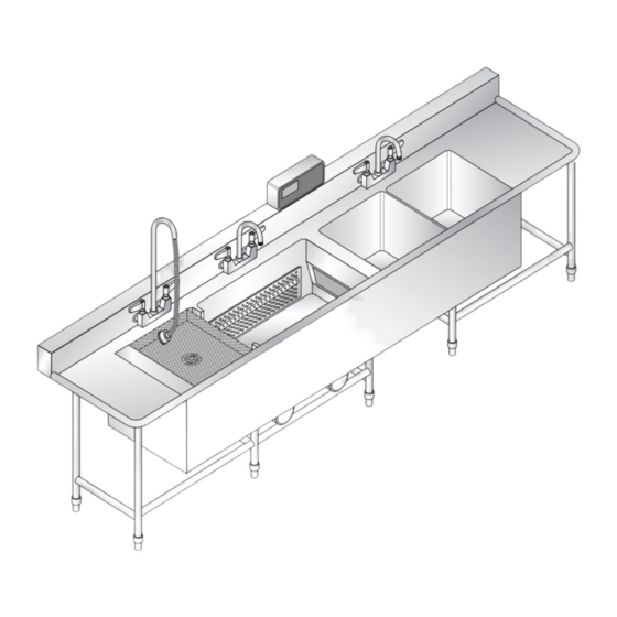
X-STREAM WASH
Please read this manual completely before attempting
to install, operate or service this equipment
This manual is Copyright © 2017 Duke Manufacturing Co. All rights reserved.
Reproduction without written permission is prohibited. Duke is a registered
trademark of the Duke Manufacturing Co.
Duke Manufacturing Co.
2305 N. Broadway
St. Louis, MO 63102
Phone: 314-231-1130
Toll Free: 1-800-735-3853
Fax: 314-231-5074
www.dukemfg.com
P/N 115152G
05/18/2017
Advertisement
Table of Contents

Subscribe to Our Youtube Channel
Related Manuals for Duke X-STREAM WASH


Summary of Contents for Duke X-STREAM WASH
- Page 1 Please read this manual completely before attempting to install, operate or service this equipment This manual is Copyright © 2017 Duke Manufacturing Co. All rights reserved. Reproduction without written permission is prohibited. Duke is a registered trademark of the Duke Manufacturing Co.
-
Page 2: Table Of Contents
Installation and Operation of X-STREAM WASH TABLE OF CONTENTS I. SAFETY AND ELECTRICAL WARNINGS ..............3 II. GENERAL INFORMATION ....................5 A. X-STREAM WASH SPECIFICATION ..............5 III. INSTALLATION INSTRUCTIONS ................6 A. QUALIFIED PERSONNEL ..................6 B. DELIVERY AND INSPECTION ................6 C. PLACEMENT ......................6 D. -
Page 3: Safety And Electrical Warnings
Installation and Operation of X-STREAM WASH I. SAFETY AND ELECTRICAL WARNINGS THIS MANUAL HAS BEEN PREPARED FOR PERSONNEL QUALIFIED TO INSTALL ELECTRICAL EQUIPMENT, WHO SHOULD PERFORM THE INITIAL FIELD STARTUP AND ADJUSTMENTS OF THE EQUIPMENT COVERED BY THIS MANUAL. READ THIS MANUAL THOROUGHLY BEFORE OPERATING, INSTALLING OR PERFORMING MAINTENANCE ON THE EQUIPMENT. - Page 4 Installation and Operation of X-STREAM WASH : Before removing any sheet metal panels or servicing this equipment, always perform the Electrical LOCKOUT/TAGOUT Procedure. Be sure all circuits are disconnected. Failure to comply with this procedure can cause property damage, injury or death.
-
Page 5: General Information
DRAIN MODEL NUMBER KEY: SSSTUVW-XXYY with suffixes. Where: Indicates the type of unit XSW – Denotes an X-Stream wash unit Indicates the options – – Denotes no options H – Denotes the heated sanitizer sink option C – Denotes that chemical injection sanitizer sink option Indicates the controller model number 1 –... -
Page 6: Installation Instructions
Installation and Operation of X-STREAM WASH III. INSTALLATION INSTRUCTIONS A. QUALIFIED PERSONNEL C. PLACEMENT These installation instructions are for the use of qualified • HANDLING – The units are very heavy and may installation and service personnel only. Installation require the use of moving equipment. Consult with or service by other than qualified personnel may result your local restaurant equipment supplier. -
Page 7: Electrical Connections
Installation and Operation of X-STREAM WASH F. XSTREAM WASH OPTIONS • Any plumbing overflows for the unit are shipped uninstalled and will need to be installed during ITEM PART NAME PART installation. See below for a depiction of the main tank overflow (Note: A main tank overflow is an option and is not provided on some units). -
Page 8: Operation Instructions
Installation and Operation of X-STREAM WASH IV. OPERATION INSTRUCTIONS A. INITIAL STARTUP A-10 Fill Tanks with Water • WASH TANK – Fill wash tank with hot water to the marked Fill Line. The water temperature should be 110˚ to 115˚ F (43˚ to 46˚ C). -
Page 9: Pre-Scrapping
Installation and Operation of X-STREAM WASH B. PRE-SCRAPPING NOTE: Pots and Pans that are stacked or nested together during the wash cycle will not be cleaned Wares should be scrapped, NOT SCRUBBED, prior properly. Pause the cycle and move them apart from to loading to remove heavy soils and debris. -
Page 10: Start The Wash Cycle
Installation and Operation of X-STREAM WASH It is recommended that not more than 10 to 12 pans be placed in the wash tank during a wash cycle. Soak in Sanitizer If your unit did not come with a sheet pan rack, one can be ordered from the factory. -
Page 11: K1000 Control Panel
Installation and Operation of X-STREAM WASH E-20 K1000 Control Panel ® K-1000 CONTROL CENTER Heater Alarm Change Water Soap WARNING START TEMP ® STOP ® Your Solutions Partner Hazardous voltage. Disconnect power before servicing machine. (800) 735-3853 K1000 Control Panel Mylar Buttons TEMP Button Press to set or display the wash tank's running temperature. - Page 12 Installation and Operation of X-STREAM WASH K-1000 Temperature Sensor Fault If the water or heater sheath temperature sensors should Basic Operation fail, the controller will indicate the fault by taking the When you first power up to use your wash tank, the controller to the FIL state.
- Page 13 Installation and Operation of X-STREAM WASH Programming – Controls Supplied After Programming – Controls Supplied Prior To 12/01/2013 12/01/2013 Supervisor Mode The programming mode can be accessed by holding the The supervisor mode can be accessed by holding the START buttons simultaneously for 5 seconds.
- Page 14 Installation and Operation of X-STREAM WASH Setup Mode – OP.S Press the TEMP button to advance between the parameters that are available, see parameter table. Enter the supervisor mode and press the Up or Down buttons until OP.5 appears in the display.
- Page 15 Installation and Operation of X-STREAM WASH Setup Mode Parameter Table Parameter Mne- Parameter Description Table 1 Table 2 Units monic Name Default Value Default Value (Fahrenheit) (Celsius) Temperature Set Setpoint 115°F 46°C Degrees Point Change Water Timer 1 4.00 4.00...
- Page 16 Installation and Operation of X-STREAM WASH Configuration Mode – CnF. Enter the supervisor mode and press the Up or Down The parameter name and its value will be swapped in buttons until CnF. is displayed. Press the TEMP button and out of the display. Press the Up and Down button to select.
-
Page 17: K5000 Control Panel
Installation and Operation of X-STREAM WASH Timer Operation E-30 K5000 Control Panel The change water timer ( t ) will retain its current count when the washer is stopped or when power is disconnected from the controller. The soap delay timer ( t2 ) allows for a delay before soap is dispensed into the wash tank. - Page 18 Installation and Operation of X-STREAM WASH K-5000 OPERATION INSTRUCTIONS TOUCH SCREEN CONTROL DEFINITIONS Status Bar Info Button Touch to access recipe programming, Status Bar diagnostics, training materials, cleaning Main Screen procedures and other tools. Recipe Buttons Turns Blue when recipe is selected.
- Page 19 Installation and Operation of X-STREAM WASH A. DAILY BROILER START-UP 1. Turn the ON/OFF power switch to the ON (I) position. The boot screen will display and then automatically transition to the main off screen. Figure: Boot Screen Figure: Main Screen 2.
- Page 20 Installation and Operation of X-STREAM WASH B. COOK PRODUCT 1. After startup is complete the Ready Screen appears. The ability to begin a wash recipe is now available through the press of the programmed recipe buttons. After the Recipe Start Button is pressed the current recipe count down timer will display with a progress bar shown below.
- Page 21 Installation and Operation of X-STREAM WASH C. SPECIAL FUNCTION SCREENS (NAVIGATION OVERVIEW) Figure: Status Bar • Access the Special Functions - PIN Code Entry Screen by selecting the info button the status bar. • Enter the PIN Code which corresponds to the desired special function screen.
- Page 22 Installation and Operation of X-STREAM WASH PROGRAMMING CONTROLS 2. Touch the button for the recipe you to edit To access the Special Functions, touch (i.e. button on the Main Tool Bar. 3. The recipe edit screen displays the option for 6 stages. Stages that are highlighted Figure: Status Bar blue are used in the total recipe.
- Page 23 Installation and Operation of X-STREAM WASH CONFIG (CONFIGURATIONS) 7. To edit the recipe name, touch the 1. Touch the button and then enter pin button for the Edit Recipe Name screen. code 2 3 4 5 and touch the button.
- Page 24 Installation and Operation of X-STREAM WASH FILES (FILE MANAGEMENT) 1. Touch the button and then enter pin code 3 4 5 6 and touch the button. Figure: Diagnostics Screen 2. Select file operation from the list and follow instructions on the display screen.
-
Page 25: Service And Repair
Installation and Operation of X-STREAM WASH V. SERVICE AND REPAIR Periodic service and maintenance of the unit is not preparation equipment. Contact the Duke Manufacturing required beyond the user’s monthly cleaning schedule. Company Service Department at the USA worldwide Qualified service personnel must perform service or... -
Page 26: Electrical Schematics
Installation and Operation of X-STREAM WASH VI. ELECTRICAL SCHEMATICS K1000 208-240V, 1 PHASE(UNITS AFTER 12/2013) - Page 27 Installation and Operation of X-STREAM WASH K1000 208-240V, 1 PHASE(UNITS TO 12/2013)
- Page 28 Installation and Operation of X-STREAM WASH K1000 208-240V, 3 PHASE (UNITS AFTER 12/2013)
- Page 29 Installation and Operation of X-STREAM WASH K1000 208-240V, 3 PHASE (UNITS TO 12/2013)
- Page 30 Installation and Operation of X-STREAM WASH K1000 440-480V, 3 PHASE (UNITS AFTER 12/2013)
- Page 31 Installation and Operation of X-STREAM WASH K1000 440-480V, 3 PHASE (UNITS TO 12/2013)
- Page 32 Installation and Operation of X-STREAM WASH K5000 208-240V, 3 PHASE WD DMC K5000 208/240V 12Vur Duke Mfg NPD-StL 3/2/17 ts Beeper Front Cover Float Sw 1 Sw 2 External P1 P2 PC Control Panel Power Switch TRIAC PCB 208 / 230V...
- Page 33 Installation and Operation of X-STREAM WASH K5000 440-480V, 3 PHASE WD DMC K5000 480V 12Vur Duke Mfg NPD-StL 3/2/17 ts Beeper Front Cover Float Sw 1 Sw 2 External P1 P2 PC Control Panel Power Switch TRIAC PCB 208 / 230V...
- Page 34 Installation and Operation of X-STREAM WASH K5000 208-240V, 3 PHASE, W/ SANITIZER...
- Page 35 Installation and Operation of X-STREAM WASH K5000 420-480V, 3 PHASE, W/ SANITIZER...
- Page 36 Installation and Operation of X-STREAM WASH Duke Manufacturing Co. 2305 N. Broadway St. Louis, MO 63102 Phone: 314-231-1130 Toll Free: 1-800-735-3853 Fax: 314-231-5074 www.dukemfg.com...
Need help?
Do you have a question about the X-STREAM WASH and is the answer not in the manual?
Questions and answers