
Subscribe to Our Youtube Channel
Related Manuals for STI CMCP7504


Summary of Contents for STI CMCP7504
- Page 1 CMCP7504 Machine Monitoring System User Manual Copyright 2022 by STI Vibration Monitoring Inc. All Rights Reserved Rev. 7.0 (March 2022) ...
- Page 2 Page 34 Dimensional Drawing Page 35 Mounting Dimensions Page 36 Revision History Page 37 STI Vibration Monitoring Inc. CMCP7504 2 ...
-
Page 3: System Overview
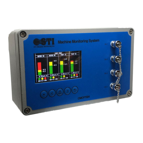
System Overview STI’s CMCP7504 is a general‐purpose monitoring system capable of continuously monitoring up to 4 channels of vibration, position, or temperature. The CMCP7504 can be configured to operate as a standalone protection system or it can be connected to a host device such as a PLC, DCS or SCADA system. Local bar graph displays provide the overall amplitudes and alarm status along with a user identifiable tag name. In addition, the CMCP7504 also allows for a single temperature input and speed input for a tag readout on the display allowing for a total of 6 measurement points. The STI CMCP7504 can accept up to four signal processing modules. Various modules are available for different sensor and measurement types. Each input module can process the signal from one sensor and up to four modules can be installed in a CMCP7504. The available input modules are: AA ‐ Acceleration Module AV ‐ Velocity Module, Accelerometer Input VV ‐ Velocity Module, Velocity Sensor Input EV ‐ Enveloped Acceleration Module, Accelerometer Input SV – Velocity Module, Seismic Velocity Sensor Input RV ‐ Radial Vibration Module, Proximity Probe Input TP ‐ Thrust Position Module, Proximity Probe Input AM ‐ Analog Input Module, 4‐20mA or 1‐5 VDC Input TM ‐ Temperature Input, 100 Ohm Platinum RTD or 10mV/Deg. C The (AA) Acceleration Module is for connecting to Piezoelectric accelerometer with a mV/g output. The signal is processed for continuous monitoring and the overall amplitude is converted into a 4‐ 20mA output, proportional to the full‐scale range selected, for transfer to a PLC, DCS or other facility control system. Acceleration can be displayed in g’s with either RMS or Peak detection. The (AV) Velocity Module is for connecting to Piezoelectric accelerometer with a mV/g output. The signal is processed for continuous monitoring and the overall amplitude is converted into a 4‐20mA output, proportional to the full‐scale range selected, for transfer to a PLC, DCS or other facility control system. Velocity can be displayed in terms of either in/sec or mm/sec with either RMS or Peak detection. The (VV) Velocity Module is for connecting to Piezo‐Velocity sensor with a mV/in/s or mV/mm/s output. The signal is processed for continuous monitoring and the overall amplitude is converted into a 4‐20mA output, proportional to the full‐scale range selected, for transfer to a PLC, DCS or other facility control system. Velocity can be displayed in terms of either in/sec or mm/sec with either RMS or Peak detection. The (EV) Enveloped Acceleration Module is for connecting to a Piezoelectric accelerometer with a mV/g output. The signal is processed to calculate an Acceleration Enveloping value within 500‐10kHz (Filter #3) for continuous monitoring and the overall amplitude is converted into a 4‐20mA output, proportional to ... - Page 4 The (RV) Radial Vibration Module is for connecting to eddy current probe systems (also referred to as a proximity probe system) with a mV/mil or mV/mm output. The signal is processed for continuous monitoring and the overall amplitude is then converted into a 4‐20mA output for transfer to a PLC, DCS or other facility control system. Radial vibration can be displayed in terms of mils or microns Peak to Peak. The CMCP7504 does not provide ‐24VDC power to the eddy probe system. The (TP) Thrust Position (Axial Position) Module is for connecting to eddy current probe system (also referred to as a proximity probe system) with a mV/mil or mV/mm output. The signal is processed for continuous monitoring and the overall amplitude is then converted into a 4‐20mA output for transfer to a PLC, DCS or other facility control system. Thrust Position can be displayed in terms of millimeters (mm) or microns (um). The CMCP7504 does not provide ‐24VDC power to the eddy probe system. The (AM) Analog Input Module is for connecting an analog signal (4‐20mA or 1‐5VDC). The signal is processed for continuous monitoring and the overall amplitude is then converted to a 4‐20mA output for transfer to a PLC, DCS or other facility control system. Analog Inputs can be displayed in the user choice of terms. The (TM) Temperature Input Module is for connecting either a 100 Ohm Platinum RTD or, most commonly, a 10mV/°C signal from a dual output accelerometer such as STI’s CMCP786T or CMCP785T. The signal is processed for continuous monitoring and the overall amplitude is then converted to a 4‐ 20mA, proportional to the full‐scale range selected, for transfer to a PLC, DCS or other facility control system. Temperature inputs can be displayed in terms of °C or °F. The (XX) Empty Slot is used for when an input module is left empty, allowing the user to order the system as a 1, 2 or 3 channel monitoring system. System Features Relays and Alarms The CMCP7504 Machine Protection System is designed to comply with the API 670 standard and offers machine protection functions. The CMCP7504 provides 2 relay contact outputs, 1 for alert and 1 for danger, for each channel. A global System OK relay is also provided. Local alarm status for each channel is also provided on the bar graph display. Buffered Outputs For each channel, the sensor’s raw signal is available as a buffered output. Buffered outputs for each channel are available at the BNC connector, located on the front cover, and at the terminal strip on the main board. These buffered outputs are commonly used to connect portable data collectors or permanently installed analysis devices in parallel to the CMCP7504 for FFT diagnostics. ...
- Page 5 AUX Temperature A single temperature input is provided on the CMCP7504 and does not require the use of an input module. The Auxiliary Temperature channel accepts a signal from a dual output accelerometer (10mV/°C) or a PT100 RTD to be connected to the system and the value displayed on the screen. Visual alarming is available if alarm limits are set. Visual alarming will change the color of the readout on the display when an alarm condition is met. Relay and analog outputs are not provided with this channel. AUX Speed A single speed input is provided on the CMCP7504 and does not require the use of an input module. The Auxiliary Speed channel accepts a signal from a 2 or 3 wire pulse output sensor and the value will be displayed on the screen. The number of events per revolution may also be programmed to allow for measuring equipment with more than 1 target. Modbus Output A Modbus TCP/IP output and RTU output are provided on the CMCP7504. See “Modbus Output” setup page. The Modbus output can be taken back to a control system for livestreaming data. DataView Overall Value Saver The DataView Overall Value Saver feature allows for recording of the overall value for each of the four channels. A removable internal SD card, with a 1 GB of memory, stores the overall values for each channel every minute. The data is saved as a .txt file and time stamped for retrieval at a later time if necessary. SignalSaver The SignalSaver feature records the sensor’s signal for 30 seconds when an alarm condition is met. The signal is saved on the removable internal SD card and is in a .wav file format. The .wav file can then be imported into a portable data collector, or online system, allowing for viewing of the time waveform and FFT. All files are timestamped and logged onto the SD card until cleared by the user. On average 1 year of data can be saved. Speed Sync Speed Sync allows the user to enable alarms when the machine speed is within a specified range when a speed sensor is connected to the monitor. To configure speed sync first setup the pulses per revolution then set the Low (L1) and High (H1) speed limits and check the “Sync Type” box for the channel you want it to apply to. When the machine speed is within this limit, the alarms will be enabled. This allows for machines to coast up and coast down without having an alarm. Configuration Utility The configuration of each channel’s processing parameters (for example the measurement units or alarm setpoints) is performed using a simple configuration software called the MMS Manager. The MMS ...
- Page 6 Push Buttons A push button keypad is used to reset the relays for each channel. To reset, click the menu button and select the channel to reset. The dotted button, far left, will display the system’s serial number and firmware version when depressed. BNC Buffered Outputs For each channel, the sensor’s raw signal is available as a buffered output at the front panel BNC connector. The BNC connectors may be used to connect a portable data collector for further signal diagnostics. Function and Parts Description (Internal) 1 2 4 3 5 1 Programming Port Type B USB programming port. Connect cable here to program using MMS application. 2 Input Module Slots (4) Four slots for installing up to four input modules. 3 Input/Output Terminals (Screw Terminals) Sensor inputs, relay outputs, 4‐20mA outputs, Modbus RTU and power connections. STI Vibration Monitoring Inc. CMCP7504 6 ...
-
Page 7: Display Overview
Red Alert (Danger) Overall Value Shown in Engineering Units, Software Programmable Channel Status (BV) Bias Voltage Green = OK Red = Not OK (AL) Alarm Yellow = Alert Red = Danger (RS) Speed Sync Off = Not Used Blue = Channel in Speed Sync Aux. Temperature Reading 10mV/°C or PT100 Input from External Sensor Aux. Speed Reading 2 or 3 Wire Tachometer or 4‐20mA Input from External Sensor STI Vibration Monitoring Inc. CMCP7504 7 ... -
Page 8: Installation
Installation The CMCP7504 should be mounted in a location where it is not exposed to unnecessary radiant heat or strong magnetic fields. Various enclosures are available through STI for the CMCP7504 which include windowed or solid door enclosures constructed of fiberglass, painted steel or stainless steel for outdoor applications. The CMCP7504 can be panel mounted using the four corner holes or a din rail mounting plate can be used to install on TS35 type din rail. Refer to page 34 for mounting dimensions. CMCP7504 Shown Installed in a Painted Steel Enclosure Cable Glands The CMCP7504 housing is provided with four pre‐drilled holes and cable glands. An M20x1.5 threaded cable gland is provided for power and three M25x1.5 glands for signal inputs and output wires. NPT adapters are available through STI. All unused openings must be closed with blind plugs or seals. Power The CMCP7504 features an internal AC to DC power supply, mounted underneath the main input board. The power supply is rated for 90‐240VAC, 50 or 60Hz. The power supply is then connected to the CMCP7504’s 24VDC input terminals. To access the AC power input terminals, remove terminal blocks #5 and #6 temporarily. The CMCP7504 may also be powered directly with 24VDC by connecting directly to the terminal block #7 (DC Power Input). STI Vibration Monitoring Inc. CMCP7504 8 ... -
Page 9: System Wiring
Ch. 1 Signal Input ‐ 2 Ch. 1 Danger Relay ‐ 3 Ch. 2 Signal Input + 3 Ch. 2 Danger Relay + 4 Ch. 2 Signal Input ‐ 4 Ch. 2 Danger Relay ‐ 5 Ch. 3 Signal Input + 5 Ch. 3 Danger Relay + 6 Ch. 3 Signal Input ‐ 6 Ch. 3 Danger Relay ‐ 7 Ch. 4 Signal Input + 7 Ch. 4 Danger Relay + 8 Ch. 4 Signal Input ‐ 8 Ch. 4 Danger Relay ‐ STI Vibration Monitoring Inc. CMCP7504 9 ... -
Page 10: Input Module Characteristics
Removing/Installing Input Modules The CMCP7504 can accept up to four input modules which allow for various types of sensors. DIP switches or jumpers for full scale range and/or frequency range selections are located on the bottom side of the module. The input modules are secured to the main board using two screws, located at the top right and bottom left corner of each module. To remove the input module, remove the two screws and lift the module up. To install, align the connectors on the input module and press down, then re‐install the two corner screws. If the screw holes do not align, remove the module and check connector alignment. Note, the CMCP7504 should always be powered off when removing or installing input modules. Input Module Characteristics The CMCP7504 supports accelerometers, velocity transducers, eddy current probes (proximity probes) and all voltage or current outputs sensors. Once processed, the data can then be used for continuous monitoring and overall value transmission to a PLC, DCS or other control system. The table below shows the standard processing parameters. When available, the frequency range can be set using a jumper or DIP switch on each input module. The frequency range is not selected using the MMS Manager. The following section will review the available full‐scale ranges and frequency ranges available for each module. Module Sensor Type High Pass Low Pass (AA) Acceleration) IEPE Accelerometer 2Hz 20kHz (AV) Velocity IEPE Accelerometer 2Hz or 10Hz 1kHz or 2kHz (VV) Velocity Piezo‐Velocity Transducer 2Hz or 10Hz 1kHz or 2kHz (SV) Seismic Velocity Electromechanical Velocity Sensor 5Hz, 10Hz or 15Hz 1kHz or 1.5kHz ... - Page 11 Range 1 Range 2 Range 3 Range 4 Range 5 Input g's g's g's g's g's 500 mV/g 0.20 0.40 0.75 0.80 1.00 100 mV/g 1.00 2.00 3.00 4.00 5.00 50 mV/g 2.00 4.00 6.00 8.00 10.00 10 mV/g 10.00 20.00 150.00 200.00 250.00 STI Vibration Monitoring Inc. CMCP7504 11 ...
- Page 12 1.00 25.00 1.50 37.50 2.00 50.00 2.50 62.50 50 mV/g 1.00 25.00 2.00 50.00 3.00 75.00 4.00 100.00 5.00 125.00 10 mV/g 5.00 125.00 10.00 250.00 15.00 375.00 20.00 500.00 25.00 625.00 Sensor Wiring STI Vibration Monitoring Inc. CMCP7504 12 ...
- Page 13 25.00 1.50 37.50 2.00 50.00 2.50 62.50 50 mV/g 1.00 25.00 2.00 50.00 3.00 75.00 4.00 100.00 5.00 125.00 10 mV/g 5.00 125.00 10.00 250.00 15.00 375.00 20.00 500.00 25.00 625.00 Sensor Wiring STI Vibration Monitoring Inc. CMCP7504 13 ...
- Page 14 200 mV/mil 5.00 127.00 10.00 254.00 15.00 381.00 20.00 508.00 25.00 635.00 (7.87 V/mm) 100 mV/mil 10.00 63.50 20.00 127.00 30.00 190.50 40.00 254.00 50.00 317.50 (3.94 V/mm) Sensor Wiring STI Vibration Monitoring Inc. CMCP7504 14 ...
- Page 15 0‐50 mils 7.87 V/mm 0‐638 um 3.94 V/mm 0‐1,270 um Note: Jumper should always remain on E2. Sensor Wiring STI Vibration Monitoring Inc. CMCP7504 15 ...
- Page 16 500 mV/g 6.00 4.00 2.00 100 mV/g 80.00 30.00 10.00 50 mV/g 60.00 40.00 20.00 10 mV/g 300.00 200.00 100.00 Sensor Wiring STI Vibration Monitoring Inc. CMCP7504 16 ...
- Page 17 OFF 16.7‐17.5 mV/mm/s OFF OFF ON Factory Default = 28.5mV/mm/s Full Scale Range: 0‐100mm/s RMS (0 to 3.9 in/s) Signal Detection: RMS or Peak (Software Selectable) Sensor Wiring STI Vibration Monitoring Inc. CMCP7504 17 ...
- Page 18 OFF ON +1 to +5VDC ON OFF OFF ‐1 to ‐5VDC OFF ON OFF to 20mA ON OFF ON Factory Default = 4 to 20mA Switches SW1 ‐ SW3 Sensor Wiring STI Vibration Monitoring Inc. CMCP7504 18 ...
- Page 19 10mV/°C OFF OFF ON ON OFF OFF Factory Default = PT100 Switches SW1 – SW6 Sensor Wiring STI Vibration Monitoring Inc. CMCP7504 19 ...
- Page 20 AUX Temperature Input When used, the Auxiliary (AUX) Temperature will allow for a single temperature channel to be shown on the display. This function can be turned on by selecting “Used” in the drop‐down menu or turned off by selecting “Not Used”. The AUX Temp input accepts either a 100 Ohm Platinum RTD or a 10mV/°C output commonly found in dual output sensors. When a dual output sensor is used, be sure the check the box in the CMCP7504 Setup Application. Sensor Wiring (PT100 RTD) Sensor Wiring (10mV/°C from Dual Output Accelerometer) Check Box for 10mV/°C Signal from Dual Output Sensor STI Vibration Monitoring Inc. CMCP7504 20 ...
- Page 21 Set Events Per Revolution (1‐8) Set Speed Sync High Limit Set Speed Sync Low Limit Number of Averages 3 Wire Tacho Wiring 2 Wire Tacho Wiring STI Vibration Monitoring Inc. CMCP7504 21 ...
- Page 22 Speed Sync Speed Sync allows the user to enable alarms when the machine speed is within a specified range. To configure Speed Sync simply turn on the Aux. Speed channel, set the number of pulses per revolution and the Low (L1) and High (H1) speed limits, in terms of RPM, then check the “Speed Sync” box next to the channel you want to apply it to. When the machine speed is between the specified range the alarms will be enabled. This allows for machines to coast up and coast down without causing alarms. The graph below shows how to enable Speed Sync for a 100 to 800 RPM range. The graph shows that the alarms will only be active between 100 and 800 RPM> When Speed Sync is enabled, a blue indicator will be displayed on the front panel to indicate that channel is tied to Speed Sync and the RPM will be displayed in the upper right corner. Machine Speed Speed Sync Active on Channel 1 STI Vibration Monitoring Inc. CMCP7504 22 ...
- Page 23 Relay Outputs The CMCP7504 has seven relay driver outputs that can be used to indicate system status, warning by alert and alarm by danger. Relay outputs can be configured by using the threshold options in the configuration program. The system relay driver is energized only when the system status is OK. The system relay driver will be de‐energized during power loss and when detecting internal system faults. Two additional relays are provided with each channel, one for Alert and one for Danger. Alert and Danger relays are configured using the configuration software and can be configured for Normally Energized or Normally De‐energized Relay Wiring Alarm Reset When alarms are set to latching, an alarm reset will need to be performed to clear the alarms. Alarms can only clear once the values drop below the alarm threshold and the reset button is depressed. An alarm condition will be shown by a Yellow (Alert) or Red (Danger) AL indicator at the bottom of the bar graph. Alarm Indicator To clear the alarm, press the OK button on the front keypad and select the channel using the left or right arrow keys. Once the channel is selected press OK. Use the return arrow button to return to the bar graph display. STI Vibration Monitoring Inc. CMCP7504 ...
- Page 24 Configuration Software Overview (MMS Manager) The MMS Manager software, provided on a USB thumb drive, allows the user to configure the following parameters; Transferring or Downloading the CMCP7504 Configuration File Set the Measurement Point Name Set Engineering Unit Selection Set Alarm and Danger Alarm Limits Set Alarm Operation (Latching or Non‐Latching) Set Alarm Time Delay Set Full Scale (Min/Max) Range Set Bar Graph View Scale Enable/Disable Auxiliary Temperature and Speed Input Settings Enable/Disable Speed Sync Configure Modbus RS485 and TCP Outputs The screenshot below shows the single page Configuration Application for the CMCP7504. Communications Driver Installation Follow the instruction below to install the driver package for the CMCP7504. Press the Windows key + X. Click Device Manager. Once device manager is open, select the device under serial bus, right click it then click Update Driver Software. This will launch the update driver software wizard. Select the Silicone Labs CP2101 driver from the USB thumb drive provided with the system and complete the installation. Once the installation is complete, restart your computer. STI Vibration Monitoring Inc. CMCP7504 24 ...
- Page 25 Connecting the CMCP7500 Configuration Program To connect to the CMCP7504 use the supplied USB‐A to USB‐B communications cable. The directions and images below will guide you through the setup. 1. Select “Setup” to setup the connection. Setup Button to Establish Communications 2. Select the COM port and verify the settings then click OK. Select COM port 3. Click Connect to Connect to the CMCP7504 Connect Button Disconnect Button STI Vibration Monitoring Inc. CMCP7504 25 ...
- Page 26 4. The configuration pre‐loaded onto the CMCP7504 may be recalled by clicking the “Load” button. All parameters from the CMCP7504 will be uploaded into the application. Load Data 5. To change the configuration, enter the information for each parameter. Once complete, click “Send All” or alternatively click “Send Set Ch” to send configuration data for each channel individually. Send All Data Send Individual Channel Set 6. To synchronize the time and date settings for DataView, click “Time Syn”. The local time from your PC will be synced to the CMCP7504 for recording the overall values. Time Sync STI Vibration Monitoring Inc. CMCP7504 26 ...
- Page 27 7. To configure the Modbus TCP IP address, enter the units IP address under the Net Config section. If necessary, a MAC address may be entered. Use the “Load” button to recall the settings from the CMCP7504 to the program. Modbus TCP IP Address Setting 8. Once setup has been complete, click Disconnect. Refer to the next section for more information on each parameter. Disconnect 9. Configuration files can be saved on a local PC and re‐opened to easily setup additional CMCP7504. Save/Load Configuration STI Vibration Monitoring Inc. CMCP7504 27 ...
- Page 28 Used/Not Used Enables/disables channel. Speed Type Speed sync allows the user to alarm between specific speeds when used with the Aux. Speed input. To active simply check the speed sync box and enter the high (H1) and low (L1) speed limits in the speed sync setup box. Engineering Units The engineering units drop down box allows the user to set the desired units in English or Metric. The selected units should match the input modules installed. The system supports both English and Metric units as well as RMS, Peak, Peak to Peak. Voltage Check Voltage check is used with Piezo style accelerometers and velocity sensors. When set to “Check” the CMCP7504 will monitor the sensors bias voltage. Voltage check must be disabled for all other sensor types. Alert and Danger Alarm Setup This section allows the user to set both the Alert and Danger (Alarm) setpoints along with the time delay and relay operation. All Danger alarm parameters are shown in red text, all Alert alarm parameters are shown in green text. Relay Type The CMCP7504 supports both Normally Energized and Normally De‐Energized relay contacts. Select NE for Normally Energized or alternatively NDE for Normally De‐Energized. ...
- Page 29 Latch Relays will remain latched until the reset button is depressed. Bypass Relays are disabled. Relay Delay Time (Seconds) A time delay of 0 to 10,000 Seconds (sec) can be added to each alarm. STI suggests using 3 to 10 second time delays. When a time delay is used, the amplitude must remain above the alarm value for the selected time before the relays change state. Signal Scaling The Signal Scaling section is used to set the CMCP7504’s analog outputs to match the configuration of the sensor input module and display. The Full Scale Min and Full Scale Max should be set according to the range selected on the sensor input module, for example, if the input module is set for a 0 to 2.00 in/sec range the Signal Full Scale Max should be set for 2.00 and Signal Full Scale Min to 0.00. View Scale The View Scale is used to adjust the CMCP7504’s bar graph display. The View Scale should match the sensor input module’s range or it can be set to display a portion of the full scale range. For example, if the range is set to 0‐5g’s, and the amplitude is typically less than 1g, the user may prefer to set the View Scale for 0 to 1g to better show the signal on the display. Scale (4‐20mA) Max and Min The CMCP7504 supports 4 different analog output ranges, 0‐20mA, 4‐20mA, 20‐4mA and 20‐0mA. By default the CMCP7504 is set to 4mA min and 20mA max for the standard 4‐20mA output range. Any of the four ranges may be entered and the scale will be proportional to the range of the input module. ...
- Page 30 Modbus Outputs Configuring the Modbus RS485 Output The CMCP7504 provides a two wire (half duplex) Modbus RS485 output for connecting to a PLC, DCS, SCADA or other system. The Modbus settings can be found in the MMS Manager. The default Baud Rate is 9600 and the Default Node ID Number is 1. The Modbus settings can be changed using the MMS Manager. Up to 4 CMCP7504’s can be connected to the same RS485 line by changing the Node ID Number from 1 to 4. Modbus RS485 Settings: Mode: RTU Modbus Address: 1 thru 4 (Default is 1) Hardware Interface: RS485 2 Wire (Half Duplex) Baud Rate: 4800, 9600, 19200 (Default is 9600) Data Bits: 8 Stop Bits: 1 or 2 (Default is 1) Parity: None, Odd or Even (Default is 1 None) Function Code: FC04 and FC03 Retries: 3 Configuring Modbus TCP Output To program the Modbus TCP output, enter the systems IP address in the Net Config section and click Set to send the configuration file to the CMCP7504, or click Load to load to view the current configuration data. If ...
- Page 31 40001 Analog 1, Overall Value Floating Point, LSRF 40003 Analog 2, Overall Value Floating Point, LSRF 40005 Analog 3, Overall Value Floating Point, LSRF 40007 Analog 4, Overall Value Floating Point, LSRF Viewing System Confirmation Setup To view the systems communication and firmware configuration, press and hold the left button on the keypad. Once depressed the display will show the system settings. STI Vibration Monitoring Inc. CMCP7504 31 ...
- Page 32 DataView – Overall Value Saver STI’s DataView Overall Value Saver continuously stores the overall value for each channel every minute, allowing users to export the data and review or trend the machine’s history. The overall values are stored on the removable Micro SD card in .txt format. The data for each channel is then displayed in the proper engineering units and in order by channel number. Refer to the CMCP7504 Configuration Program or the CMCP7504’s local display for measurement type and engineering units. SignalSaver File SignalSaver File Folders (.wav file) DataView Files (.txt file) The data shown in the txt file represents the overall value for each channel and is shown in engineering units. Each txt file is saved by Month/Day/Year/Recording Number. STI Vibration Monitoring Inc. CMCP7504 32 ...
- Page 33 SignalSaver – Raw Signal Recording STI’s SignalSaver feature automatically records the sensor’s raw signal for 30 seconds when an alarm condition is detected. To enable, simply set the alarm limits for each channel and be sure the SD card is installed on the main circuit board. The CMCP7504 will automatically record the sensor’s signal and save it as a .wav file which can then be exported to a portable data collector or online condition monitoring system for fault analysis. The files are stored on the SD card in the channels folder, for example signals for Channel 1 can be found in the CH1 folder, signals for Channel 2 can be found in the CH2 folder. File names are saved by Month/Day/Year/Recording Number. The image below shows the .wav file in waveform and FFT format when viewed using a Microlog GX. Refer to your device’s manual for instructions on uploading .wav files. STI Vibration Monitoring Inc. CMCP7504 33 ...
-
Page 34: Technical Specifications
Power Coated Gray Dimensions: 10.24” x 6.3” x 3.54” (260x160x90mm Mounting Options: 4 Hole Corner Mount Optional Din Rail Mounting Plate Cable Entries: 3 Each M25x1.5 Threaded Hole, Cable Glands Provided 1 Each M20x1.5 Threaded Hole, Cable Gland Provided Software Compatibility: Windows 10, Windows 11 Driver: Silicone Labs CP2101 USB to UART Bridge Controller https://www.silabs.com/documents/public/software/CP210x_Universal_Windows_Driver.zip STI Vibration Monitoring Inc. CMCP7504 34 ... - Page 35 Dimensions STI Vibration Monitoring Inc. CMCP7504 35 ...
-
Page 36: Mounting Dimensions
Mounting Dimensions: STI Vibration Monitoring Inc. CMCP7504 36 ... - Page 37 Updated Application Images December 2, 2019 3.0 Added SignalView, SignalSaver March 22, 2020 4.0 Added SpeedSync November 15, 2021 5.0 Added Modbus TCP Instructions and Setup Info December 14, 2021 6.0 Revised Register Map March 16, 2022 7.0 Revised Programming for Version 4.0 Software STI Vibration Monitoring Inc. CMCP7504 37 ...
Need help?
Do you have a question about the CMCP7504 and is the answer not in the manual?
Questions and answers