
Related Manuals for STI CMCP7504


Summary of Contents for STI CMCP7504
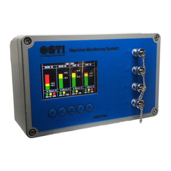
- Page 1 CMCP7504 Machine Monitoring System User Manual Copyright 2018 by STI Vibration Monitoring Inc. All Rights Reserved Rev. 2.0...
-
Page 2: Table Of Contents
Table of Contents System Overview ............................4 Introduction to the CMCP7504 ......................... 4 Additional System Features .......................... 5 Function and Parts Description ......................... 6 Input Module Characteristics ........................6 Frequency Ranges ............................. 6 Setting The Full Scale Range and Frequency Ranges ................7 (AA) Acceleration Module ........................ - Page 3 Uploading Configuration File (Load File) ..................... 22 Configuring the Modbus RS485 Output ...................... 22 Modbus Communications Setup ......................22 Technical Specifications ..........................23 Sample Wiring Diagrams ..........................24 STI Vibration Monitoring Inc. CMCP7504...
-
Page 4: System Overview
STI’s CMCP7504 is a general-purpose monitoring system capable of continuously monitoring up to 4 channels of vibration, position or temperature. The CMCP7504 can be configured to operate as a standalone protection system or it can be connected to a host device such as a PLC, DCS or SCADA system. -
Page 5: Additional System Features
Modbus Output A two wire Modbus 485 (half duplex) output is available on the internal terminal strips. The CMCP7504 can be configured to act as a slave device to allow the overall values to be sent over Modbus 485. -
Page 6: Function And Parts Description
Input Module Characteristics The CMCP7504 supports accelerometers, velocity transducers, eddy current probes (proximity probes) and all voltage or current outputs sensors. Once processed, the data can then be used for continuous monitoring and overall value transmission to a PLC, DCS or other control system. The table below shows the standard processing parameters. -
Page 7: Setting The Full Scale Range And Frequency Ranges
(TM) Temperature Input 100 Ohm RTD or 10mV/°C Table 1: Available Sensor Inputs and Characteristics for the CMCP7504 Setting The Full Scale Range and Frequency Ranges The following section will review the available full-scale ranges and frequency ranges available for each module. -
Page 8: (Av) Velocity Module - Accelerometer Input
SW 4 10Hz to 1kHz 2Hz to 2kHZ ICP Power Options SW 1 Sensor Wiring Signal Type Sensor Function CMCP7504 Terminal Standard Accelerometer (ICP/IEPE) Power Signal/Pwr (+) Sig (+) Com (0V) Ground (-) Shield Shield STI Vibration Monitoring Inc. CMCP7504... -
Page 9: (Vv) Velocity Module Input - Velocity Sensor Input
Range 4 Range 5 Frequency Range Jumper Settings 10Hz to 1kHz 2Hz to 2kHZ Sensor Wiring Signal Type Sensor Function CMCP7504 Terminal Velocity Transducer (IEPE) Power Signal/Pwr (+) Sig (+) Com (0V) Ground (-) Shield Shield STI Vibration Monitoring Inc. CMCP7504... -
Page 10: (Rv) Radial Vibration Module- Proximity Probe Input
Full Scale Range Jumper Settings Range 1 Range 2 Range 3 Range 4 Range 5 Sensor Wiring Signal Type Sensor Function CMCP7504 Terminal Eddy Current Probe Power Signal/Pwr (+) Sig (+) Com (0V) Ground (-) Shield Shield STI Vibration Monitoring Inc. CMCP7504... -
Page 11: (Ev) Enveloped Acceleration Module- Accelerometer Input
100.00 200.00 300.00 (EV) Acceleration Module Ranges Range 1 Range 2 Range 3 Sensor Wiring Signal Type Sensor Function CMCP7504 Terminal Standard Accelerometer (ICP/IEPE) Power Signal/Pwr (+) Sig (+) Com (0V) Ground (-) Shield Shield STI Vibration Monitoring Inc. CMCP7504... -
Page 12: (Am) Analog Input Module - Voltage Or Current
Sensor Wiring Signal Type Sensor Function CMCP7504 Terminal 4-20mA Source Power Sig (+) + Signal Ground (-) - Signal Shield 4-20mA (CMCP7504 Powered) Signal + Power Sign (+) Ground (-) Shield Shield Voltage Source Power Sig (+) + Signal Ground (-) -
Page 13: (Tm) Analog Input Module - Voltage Or Current
(TM) Analog Input Module – Voltage or Current The default factory setup is 10mV/°C to accept an input from a dual output accelerometer such as the CMCP786T. Input Type Table PT100 10mV/°C Sensor Wiring STI Vibration Monitoring Inc. CMCP7504... -
Page 14: General Wiring
General Wiring Buffered Outputs and Analog Outputs TS 1 TS 2 4-20mA Outputs Buffered Outputs & Modbus RS485 STI Vibration Monitoring Inc. CMCP7504... -
Page 15: Analog Inputs
Analog Inputs TS 3 TS 4 Signal Inputs - Channels 1 & 2 Signal Inputs - Channels 3 & 4 STI Vibration Monitoring Inc. CMCP7504... -
Page 16: Alert And Danger Relay Outputs
Alert and Danger Relay Outputs TS 5 TS 6 Relay Outputs - Channels 1 & 2 Relay Outputs - Channels 3 & 4 STI Vibration Monitoring Inc. CMCP7504... -
Page 17: System Ok Relay And System Power
System OK Relay and System Power TS 7 OK Relay and Power STI Vibration Monitoring Inc. CMCP7504... -
Page 18: Configuration Software Overview (Mms Manager)
4-20mA Output Scaling • 4-20mA Offset The screenshots below will show how the MMS Software Manager is used to program the CMCP7504. Measurement Point Name The user can input any “Point Name” desired through abbreviations or full words, however, spacing is limited to 12 characters. -
Page 19: Engineering Units
When the relays are set to non-latching, the relays will automatically clear once the amplitude drops below the programmed threshold. When the relays are set to latching, the relays will hold their state until the reset button is depressed. STI Vibration Monitoring Inc. CMCP7504... -
Page 20: Bypass
A time delay of 0 to 10,000 milliseconds (ms) can be added to each alarm Signal Scaling The Signal Scaling section is used to set the CMCP7504’s analog outputs to match the configuration of the sensor input module and display. The Full Scale Min and Full Scale Max should be set according to the range selected on the sensor input module, for example, if the input module is set for a 0 to 2.00 in/sec... -
Page 21: View Scale
View Scale The View Scale is used to adjust the CMCP7504’s bar-graph display. The View Scale should match the sensor input modules range or it can be set to display over-range readings as well. 4-20mA Offset The 4-20mA offset is calibrated by the factory at the time of shipment and should not be changed unless advised by the factory. -
Page 22: Uploading Configuration Files (Set Data)
Uploading Configuration File (Load File) If a local copy of the configuration file cannot be found, connect a USB cable to the CMCP7504 and click “Load File”. A copy of the existing program on the CMCP7504 will be uploaded to your computer and can be saved to your local drive. -
Page 23: Technical Specifications
Operating Temperature: -20 to 80°C (-4 to 176°F) Storage Temperature: -55 to 125°C (-67 to 257°F) Humidity: 0-90% Relative Humidity, Non-Condensing IP Rating: IP65 Mechanical Weight: 6.5 lb (2.95kg) Color: Power Coated Gray Dimensions: 10.24” x 6.3” x 3.54” (260x160x90mm) STI Vibration Monitoring Inc. CMCP7504... -
Page 24: Sample Wiring Diagrams
Sample Wiring Diagrams IEPE Accelerometer or Velocity Transducer Dual Output Accelerometer with Temperature Eddy Current Probe STI Vibration Monitoring Inc. CMCP7504... - Page 25 100 Ohm Platinum RTD (PT100) 4-20mA Loop Powered Sensor (2 Wire) 4-20mA Source (3 Wire) STI Vibration Monitoring Inc. CMCP7504...
Need help?
Do you have a question about the CMCP7504 and is the answer not in the manual?
Questions and answers