Carrier 38YRA Installation And Start-Up Instructions Manual
Outdoor section
Hide thumbs
Also See for 38YRA:
- Installation and start-up instructions manual (13 pages) ,
- Product data (40 pages)
Table of Contents
Advertisement
Quick Links
Installation and Start-Up Instructions
NOTE: Read the entire instruction manual before starting the
installation.
This symbol
indicates a change since last issue.
SAFETY CONSIDERATIONS
Improper installation, adjustment, alteration, service, maintenance,
or use can cause explosion, fire, electrical shock, or other
conditions which may cause personal injury or property damage.
Consult a qualified installer, service agency, or your distributor or
branch for information or assistance. The qualified installer or
agency must use factory-authorized kits or accessories when
modifying this product. Refer to the individual instructions pack-
aged with the kits or accessories when installing.
Follow all safety codes. Wear safety glasses and work gloves. Use
quenching cloth for brazing operations. Have fire extinguisher
available. Read these instructions thoroughly and follow all
warnings or cautions attached to the unit. Consult local building
codes and the National Electrical Code (NEC) for special instal-
lation requirements.
Recognize safety information. This is the safety-alert symbol
When you see this symbol on the unit or in instructions and
manuals, be alert to the potential for personal injury.
Understand the signal word DANGER, WARNING, or CAU-
TION. These words are used with the safety-alert symbol. DAN-
GER identifies the most serious hazards which will result in severe
personal injury or death. WARNING signifies hazards which
could result in personal injury or death. CAUTION is used to
identify unsafe practices which would result in minor personal
injury or product and property damage.
Before installing or servicing system, always turn off main
power to system. There may be more than 1 disconnect
switch. Turn off accessory heater power if applicable. Elec-
trical shock can cause personal injury or death.
INSTALLATION
Step 1—Check Equipment and Jobsite
UNPACK UNIT — Move to final location. Remove carton taking
care not to damage unit.
INSPECT EQUIPMENT — File claim with shipping company,
prior to installation, if shipment is damaged or incomplete. Locate
unit rating plate on unit corner panel. (See Fig. 2.) It contains
information needed to properly install unit. Check rating plate to
be sure unit matches job specifications.
Step 2—Install on a Solid, Level Mounting Pad
If conditions or local codes require the unit be attached to pad,
tie-down bolts should be used and fastened through knockouts
provided in unit base pan. Refer to unit mounting pattern in Fig. 2
to determine base pan size and knockout hole location.
When installing, allow sufficient space for airflow clearance,
wiring, refrigerant piping, and service. Allow 30-in. clearance to
service end of unit and 48 in. above unit. For proper airflow, a 6-in.
Manufacturer reserves the right to discontinue, or change at any time, specifications or designs without notice and without incurring obligations.
Book 1 4
PC 101
Catalog No. 533-890
Tab 5a 5a
Heat Pump—Outdoor Section
.
clearance on 1 side of unit and 12 in. on all remaining sides must
be maintained. Maintain a distance of 24 in. between units.
Position so snow, ice, and water from roof or eaves cannot fall
directly on unit.
On rooftop applications, locate unit at least 6 in. above roof
surface. Place unit above a load-bearing wall and isolate unit and
tubing set from structure.
Arrange supporting members to adequately support unit and
minimize transmission of vibration to building. Consult local
codes governing rooftop applications.
Step 3—Elevate Unit
For proper drainage the heat pump must be raised off the mounting
surface. Fig. 4 shows unit with accessory support feet installed.
Use accessory heat pump snow rack in areas where prolonged
subfreezing temperatures or heavy snow occur. Refer to separate
Installation Instructions packaged with the accessories.
For proper unit operation and reliability, this unit must be
installed with the field-supplied balance port, hard shut-off
TXV. Do not install with evaporator coils having capillary
tube metering devices.
Step 4—Remove Indoor AccuRater® Piston and Install
TXV
After removing existing AccuRater from indoor coil, install
field-supplied bi-flow hard shut-off TXV kit. (See Fig. 5 and 6.)
For TXV kit part number and charging instruction, refer to TXV
label in your unit. If the indoor unit (fan coil) comes factory-
equipped with a bi-flow hard shut-off TXV, no TXV change is
required.
Printed in U.S.A.
Form 38YRA-2SI
38YRA
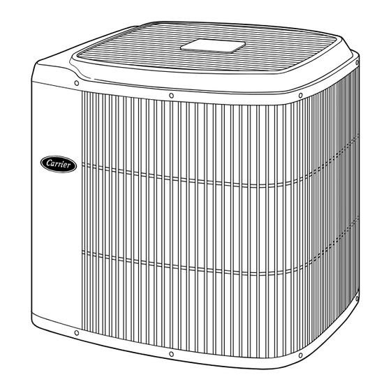
Fig. 1—Model 38YRA
Pg 1
8-95
Replaces: 38YRA-1SI
A92446
Advertisement
Table of Contents

Related Manuals for Carrier 38YRA


Summary of Contents for Carrier 38YRA
- Page 1 Consult local codes governing rooftop applications. Step 3—Elevate Unit For proper drainage the heat pump must be raised off the mounting surface. Fig. 4 shows unit with accessory support feet installed. Use accessory heat pump snow rack in areas where prolonged subfreezing temperatures or heavy snow occur.
- Page 2 VOLTS AC FAN MOTOR VOLTS AC DESIGN/TEST PRESSURE GAGE MINIMUM CIRCUIT AMPS ACCESS MAX OVERCURRENT PROTECTIVE DEVICE PANEL TYPE CANADA MAX FUSE MAX HACR CKT-BKR MAX CKT-BKR ® ® CARRIER CORP INDIANAPOLIS IN 313948-401 REV A 46206 9-3/4 5-15/16 11-13/16 A92471...
- Page 3 7. Do not suspend refrigerant tubing from joists and studs with a rigid wire or strap which comes in direct contact with the tubing. (See Fig. 3.) NOTE: Avoid contact between tubing and structure OUTDOOR WALL INDOOR WALL CAULK INSULATION THROUGH THE WALL HANGER STRAP (AROUND VAPOR...
- Page 4 INSIDE STRAINER FLARE NUT FLARE ADAPTER PISTON LIQUID SERVICE VALVE Fig. 7—Service Valve with Sweat Adapter Tube A brazing shield MUST be used when tubing sets are being brazed to the service valves to prevent damage to the painted unit surface. Relieve pressure and recover all refrigerant before system repair or final unit disposal to avoid personal injury or death.
- Page 5 5. Set room thermostat at HEAT or COOL and fan switch at ON or AUTO, as desired. Operate unit for 15 minutes. Check system refrigerant charge. (See Step 10.) SEQUENCE OF OPERATION — With power supplied to indoor and outdoor units, transformer is energized. Cooling On a call for cooling, the thermostat makes circuits R-O, R-Y, and R-G.
- Page 6 NOT USED NOT USED TROUBLE OPTIONAL OUTDOOR SENSOR CONNECTION Fig. 9—Typical 24-v Circuit Connections DUAL FUEL THERMOSTAT 24 VAC HOT HEAT PUMP FURNACE LO COMPRESSOR RVS COOLING FURNACE HI 24 VAC COM RVS HEATING RVS SENSING OUTDOOR SENSOR CONNECTION A95215...
- Page 7 CORPORATE NON-PROGRAMMABLE THERMOSTAT FK4B MODEL HP FAN COIL 24 VAC HOT 24 VAC COM HEAT STAGE 2 W/W1 COOL/HEAT Y/Y2 Y/Y2 STAGE 1 INDOOR FAN RVS COOLING O/W2 NOT USED NOT USED TROUBLE OPTIONAL OUTDOOR SENSOR CONNECTION CORPORATE NON-PROGRAMMABLE THERMOSTAT FK4C HEAT MODEL HP...
- Page 8 5. To stage the electric resistance heat, consult outdoor thermostat installation instructions. Copyright 1995 CARRIER Corp. • 7310 W. Morris St. • Indianapolis, IN 46231 Manufacturer reserves the right to discontinue, or change at any time, specifications or designs without notice and without incurring obligations.
Need help?
Do you have a question about the 38YRA and is the answer not in the manual?
Questions and answers