Table of Contents
Advertisement
Advertisement
Table of Contents

Related Manuals for Furuno PP-505


Summary of Contents for Furuno PP-505
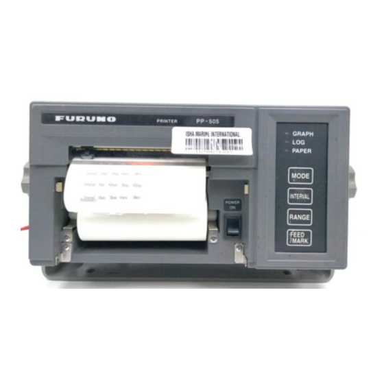
- Page 1 PRINTER PP-505 (For FE-700)
- Page 2 Serious injury can result if the power is not turned off, or is applied while the equipment is being installed. CAUTION Observe the following compass safe distances to prevent interference to a magnetic compass: standard compass PP-505 1.1 m steering compass 0.8 m...
- Page 3 WARNING LABEL A warning label is attached to the printer. Do not remove the label. If the label is missing or damaged, contact your dealer about replacement. Name: Warning Label (1) WARNING Type: 86-003-1011 To avoid electrical shock, do not Code No.: 100-236-231...
- Page 4 We would appreciate hearing from you, the end-user, about whether we are achieving our purposes. Thank you for considering and purchasing FURUNO equipment. The PP-505 prints a depth graph or a log consisting of date, time, depth, draft, latitude, longitude and heading. You can choose which to print with the [MODE] key.
-
Page 5: Table Of Contents
REPLACEMENT OF THERMAL PAPER ... 3 INSTALLATION ... 4 Complete Set ...4 General Mounting Considerations...4 Tabletop/Bulkhead Mount ...5 Flush Mount ...5 Wiring ...6 MAINTENANCE ... 7 APPENDIX REPLACEMENT OF PRINTER ASSEMBLY/THERMAL HEAD AP-1 SPECIFICATIONS... SP-1 PACKING LIST OUTLINE DRAWING INTERCONNECTION DIAGRAM... -
Page 6: Operation
1. OPERATION General Operation of the PP-505 is simple; just turn on the power. The depth graph or the log, whichever is selected for printing, is printed out at the interval set. Below are example printouts. 2003/12/01 13:05:00 038.6m/01.0m 35 20.02’N/135 45.15’E 15.1kt 008.0deg... -
Page 7: Turning On The Power
Turning on the Power Flip down the thermal paper cover and turn on the [POWER] switch. The PP-505 then carries out the diagnostic test. After the test has been completed, the printer is ready to 450 s print depth data. -
Page 8: Replacement Of Thermal Paper
8. Press the [MODE] key to complete the replacement of thermal paper. (The PAPER LED goes off.) Reel Note: If the PP-505 receives data when there is no paper it doesn’t print them out after replacing the thermal paper. Remedy for paper jam If the paper is jammed cut it off at the front panel and rewind it into the paper container. -
Page 9: Installation
Keep in mind the following when selecting a mounting location. Water spray The PP-505 is designed and constructed to be able to withstand the humidity and corrosive atmosphere common to the pilothouse, but it is not designed to be used outside, directly exposed to the environment. -
Page 10: Tabletop/Bulkhead Mount
Tabletop/Bulkhead Mount The main unit can be mounted on a desktop, bulkhead, or in a panel. Make sure the selected location is strong enough to support the main unit against possible vibration and shock. If necessary, appropriate reinforcement measures should be made on the mounting area. -
Page 11: Wiring
3. INSTALLATION 1. Referring to the illustration below, prepare a cutout in the mounting area and drill four pilot holes for the flush mount angles. Refer to the outline drawing at end of manual. 2. Fix the liner and the flush mount angles to the main unit. -
Page 12: Maintenance
4. MAINTENANCE Checking the power connector Check for loosened or disconnected power connector. WARNING Do not open the cover of the equipment. This equipment uses high voltage electricity which can shock or burn. Only qualified personnel should work inside the equipment. - Page 13 APPENDIX PRINTER ASSEMBLY/TERMAL HEAD 1. Loosen the four M4 × 15 screws fixing the rear cabinet to the main unit assembly. 2. Disconnect the connectors connected to the rear cabinet to detach the rear cabinet. Main Unit Assembly 3. Separate the panel assembly from the main unit assembly by removing the recording paper from the paper container.
-
Page 14: Appendix Replacement Of Printer Assembly/Thermal Head
Cable (Connector) 7. Remove the thermal head from the head holder with a screwdriver as shown below, and then take the thermal head assembly out of the printer assembly. Thermal Head Head Holder 8. As shown below, pass the flexible cable (connector side) of a new thermal head assembly beneath the guide pins. - Page 15 11. Fix the flexible cable to the carriage with the flexible cable support, inserting the projection on the carriage into the hole of the cable. Flexible Cable Support Projection 12. Fold back the end of the cable and insert it into the connector. End of Flexible Cable Carriage...
-
Page 16: Specifications
Print Speed Roll Paper RATED VOLTAGE/CURRENT ENVIRONMENTAL CONDITION Ambient Temperature Relative Humidity Waterproofing Vibration COATING COLOR PP-505 RS-232C 9600 bps 8 bits 1 bit 9 dots serial thermal head printing system Alphanumeric 0.28 mm/ dot 300 dots Max. 80 characters/ line...
Need help?
Do you have a question about the PP-505 and is the answer not in the manual?
Questions and answers