Table of Contents
Advertisement
Available languages
Available languages
Quick Links
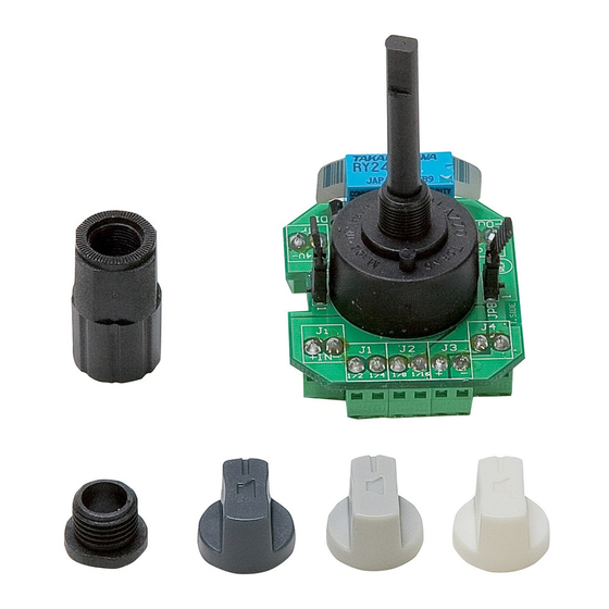
6 POSITION SELECTOR TO BE MATCHED
TO THE TL 128 LINE TRANSFORMER (or equivalent)
IN ORDER TO GET A (MAX.) 120 W VOLUME CONTROL.
COMMUTATORE A 6 POSIZIONI DA ABBINARE
AL TRASFORMATORE DI LINEA RCF TL128
(o equivalente) PER OTTENERE UN ATTENUATORE
CON POTENZA MAX. 120 W.
User manual
Manuale d'uso
the rules of sound
CT61
Advertisement
Table of Contents

Subscribe to Our Youtube Channel
Related Manuals for RCF CT61


Summary of Contents for RCF CT61
- Page 1 TO THE TL 128 LINE TRANSFORMER (or equivalent) IN ORDER TO GET A (MAX.) 120 W VOLUME CONTROL. COMMUTATORE A 6 POSIZIONI DA ABBINARE AL TRASFORMATORE DI LINEA RCF TL128 (o equivalente) PER OTTENERE UN ATTENUATORE CON POTENZA MAX. 120 W.
-
Page 2: Table Of Contents
RCF S.p.A. L’installazione e l’utilizzo errati del prodotto esimono la da ogni responsabilità. - Page 3 Non collegare al commutatore apparecchi ed accessori non previsti. Verificare l’idoneità del supporto (parete, struttura, ecc.) e dei componenti utilizzati per il fissaggio (non forniti da RCF) che devono garantire la sicurezza dell’impianto / installazione nel tempo, anche considerando, ad esempio, vibrazioni meccaniche normalmente generate da un trasduttore.
-
Page 4: Descrizione Pag
RCF S.p.A. Vi ringrazia per l’acquisto di questo prodotto, realizzato in modo da garantirne l’affidabilità e prestazioni elevate. DESCRIZIONE CT 61 Il commutatore a 6 posizioni (5 + off) abbinato ad un trasformatore di RCF TL 128 linea (non incluso) - Page 5 Esempio nr. 1: collegamento base con 2 fili • un ingresso audio (100 V) Il segnale d’ingresso 100V (IN) è collegato direttamente ai morsetti Ji+ , Ji- (0, comune) ed al trasformatore (100 V, 0), le cui uscite con tensioni intermedie 70V, 50V, 35V e 25V sono rispettivamente connesse ai morsetti J1 1/2, J1 1/4, J2 1/8, J2 1/16.
- Page 6 Esempio nr.2: collegamento con comando per annunci (linea con 4 fili) • un ingresso audio (100 V) • un comando a 24 V c.c. Il segnale d’ingresso 100 V (IN) è collegato direttamente ai morsetti Ji+ , Ji- (0, comune) ed al trasformatore (100 V, 0), le cui uscite con tensioni intermedie sono connesse ai morsetti J1 1/2, J1 1/4, J2 1/8, J2 1/16.
- Page 7 Esempio nr.3: collegamento con comando e linea audio per annunci (linea con 6 fili) • un ingresso audio “IN A” principale (100 V) • un secondo ingresso audio “IN B” per annunci (100 V) • un comando a 24 V c.c. Il segnale d’ingresso 100 V (IN A) è...
- Page 8 100 V 100 V 0 / 100 V Esempio nr.4: collegamento con linea a 3 fili • un ingresso audio (100 V) con 3° filo (scambio 0 – 100 V)
-
Page 9: Installazione Pag
La linea del segnale d’ingresso 100V presenta 3 fili: 100 V; commutazione 0 (funzionamento normale) / 100 V (annunci). Il primo (100 V) ed il terzo filo (commutazione 0 / 100 V) sono collegati direttamente rispettivamente ai morsetti Ji+, Ji- (0, comune) ed al trasformatore (100 V, 0), le cui uscite con tensioni intermedie 70V, 50V, 35V e 25V sono rispettivamente connesse ai morsetti J1 1/2, J1 1/4, J2 1/8, J2 1/16;... -
Page 10: Dati Tecnici Pag
DATI TECNICI Max. tensione ingresso / uscita 100 V Max. potenza applicabile 120 W (abbinato al trasformatore RCF TL 128) Dimensioni commutatore 43 mm (l), 50 mm (h), 68 mm (p) (senza manopola) Peso commutatore ca. 40 g... -
Page 11: English Index
RCF S.p.A. will not assume any responsibility for the incorrect installation and / or use of this product. - Page 12 Check the suitability of the support surface (wall, structure, etc., which the product is anchored to) and the components used for attachment (not supplied by RCF) that must guarantee the security of the system / installation over time, also considering, for example, the mechanical vibrations normally generated by transducers.
-
Page 13: Description
RCF S.p.A. would like to thank you for purchasing this product, which has been designed to guarantee reliability and high performance. DESCRIPTION CT 61 The 6 (5 + off) position selector shall be matched to a (not included) RCF TL 128... - Page 14 Example no. 1: basic 2 wire connection • an audio input (100 V) The 100 V input (IN) is directly connected to the Ji+ , Ji- (0, common) terminals and the transformer (100 V, 0), of which outputs having intermediate voltages 70V, 50V, 35V, 25V are respectively connected to the J1 1/2, J1 1/4, J2 1/8, J2 1/16 terminals.
- Page 15 Example no.2: connection with override relay (4 wire line) • an audio input (100 V) • a 24 V dc command The 100 V input (IN) is directly connected to the Ji+ , Ji- (0, common) terminals and the transformer (100 V, 0), of which outputs having intermediate voltages 70V, 50V, 35V, 25V are respectively connected to the J1 1/2, J1 1/4, J2 1/8, J2 1/16 terminals.
- Page 16 Example no.3: connection with the second audio line and the override relay (6 wire line) • an audio input (100 V), “IN A” • another audio input (100 V), “IN B” • a 24 V dc command The (100 V) IN A input is directly connected to the Ji+ , Ji- (0, common) terminals and the transformer (100 V, 0), of which outputs having intermediate voltages 70V, 50V, 35V, 25V are respectively connected to the J1 1/2, J1 1/4, J2 1/8, J2 1/16 terminals.
- Page 17 100 V 100 V Example no.4: 0 / 100 V 3 wire connection • an audio input (100 V) with 3rd wire (0 – 100 V exchange) The 100 V input signal has 3 wires: 100 V; 0 (normal) / 100 V (override) commutation.
-
Page 18: Installation
The first (100 V) and the third wire (0 / 100 V commutation) are directly connected (respectively) to the Ji+, Ji- terminals and the transformer (100 V, 0), of which outputs having intermediate voltages 70V, 50V, 35V, 25V are respectively connected to the J1 1/2, J1 1/4, J2 1/8, J2 1/16 terminals. -
Page 19: Specifications
Add one of the 3 available knobs. SPECIFICATIONS Max. input / output voltage 100 V Max. power 120 W (matched to the RCF TL 128 transformer) Selector dimensions 43 mm (w), 50 mm (h), 68 mm (d) (without a knob) Selector weight ca. 40 g... - Page 20 Except possible errors and omissions. RCF S.p.A. reserves the right to make modifications without prior notice. the rules of sound RCF SpA: Via Raffaello, 13 - 42100 Reggio Emilia > Italy tel. +39 0522 274411 - fax +39 0522 274484 - e-mail: rcfservice@rcf.it...
Need help?
Do you have a question about the CT61 and is the answer not in the manual?
Questions and answers