Table of Contents
Advertisement
Available languages
Available languages
Quick Links
To prevent possible SERIOUS INJURY or DEATH from a closing door:
• Be sure to DISCONNECT POWER to the operator BEFORE installing the photoelectric sensor.
• The door MUST be in the fully opened or closed position BEFORE installing the LiftMaster
• Correctly connect and align the photoelectric sensor.
• Install the photoelectric sensor beam NO HIGHER than 6" (15 cm) above the fl oor.
• LiftMaster
®
Monitored Entrapment Protection devices are for use with LiftMaster
warranty.
• Entrapment protection devices MUST be installed per the operator owner's manual for each Entrapment Zone.
APPLICATION
LiftMaster
®
Protector System model CPS-OPEN4 is a monitored entrapment protection device for use with sectional and rolling doors. This device is
compatible with LiftMaster Heavy, Standard, and Medium Duty Logic (post 2010), FDC, FCL, FDOA, FDOB, and Egress Commercial Door operators. This
device may be installed in areas exposed to rain or moisture. These images in this document are for reference only and your product may look different.
SPECIFICATIONS
Power Consumption: Max. 50mA
Supply Voltage: 6 to 40 Vdc
Operating Temperature: -13°F to 165°F (-25°C to 73°C)
NEMA4 rating
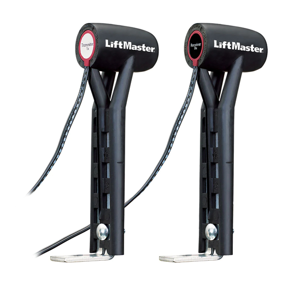
CARTON INVENTORY
Photoelectric sensors (transmitter and receiver), mounting brackets (2), hardware, and instructions
LIFTMASTER
®
PROTECTOR SYSTEM
IMPORTANT INFORMATION ABOUT THE PHOTOELECTRIC SENSOR
Be sure power to the operator is disconnected.
When properly connected and aligned, the photoelectric sensor will detect an obstruction in the path of its beam. If an obstruction breaks the beam while
the door is closing, the operator will stop and typically reverse to the full open position.
The transmitter must be installed so that it faces the receiver across the entrapment zone, no more than 6" (15 cm) above the fl oor for a door. Minimum
Installation width of 3 feet (.91 m) and maximum width of 45 feet (13.7 m).
The brackets must be securely fastened to a solid surface such as the wall framing. If installing in masonry construction, add a piece of wood at each
location to avoid drilling extra holes in masonry if repositioning is necessary.
The invisible light beam path must be unobstructed. No part of the door (or door tracks, springs, hinges, rollers or other hardware) may interrupt the
beam while the door is closing.
ENTRAPMENT ZONES
Make sure the brackets are aligned so the photoelectric sensors will face each other across the entrapment zone as illustrated.
ENTRAPMENT ZONE FOR COMMERCIAL DOOR APPLICATION
6" (15 cm) max. above the
floor and away from the door
Entrapment Zone
Photoelectric
Sensor
Facing the door from inside the building
(Installation procedures are the same for all door types)
LIFTMASTER
®
Monitored Entrapment Protection device.
®
Commercial Door. Use with ANY other product voids the
Invisible Light Beam
Protection Area
1
®
PROTECTOR SYSTEM
MODEL CPS-OPEN4
Photoelectric
Sensor
6" (15 cm) max. above the
floor and away from the door
Advertisement
Table of Contents

Subscribe to Our Youtube Channel
Related Manuals for Chamberlain CPS-OPEN4


Summary of Contents for Chamberlain CPS-OPEN4
- Page 1 ® Protector System model CPS-OPEN4 is a monitored entrapment protection device for use with sectional and rolling doors. This device is compatible with LiftMaster Heavy, Standard, and Medium Duty Logic (post 2010), FDC, FCL, FDOA, FDOB, and Egress Commercial Door operators. This device may be installed in areas exposed to rain or moisture.
- Page 2 INSTALLATION 1. Attach the mounting brackets to a solid surface on each side of the door with hardware (provided) no more than 6" (15 cm) above the fl oor. NOTE: Track mount is not recommended. 2. Loosen the wing nut and slide the mounting bracket to adjust the photoelectric sensor. Mounting Bracket 6"...
- Page 3 WIRING Do not run wiring in the same conduit with AC power. 1. Disconnect power to the operator. 2. Run wire from both photoelectric sensors to the operator. 3. Connect wires from the photoelectric sensors as illustrated below for your operator type. The wiring is polarity sensitive so make certain to wire as indicated.
- Page 4 ALIGN THE PHOTOELECTRIC SENSORS The photoelectric sensors must be on the same horizontal plane to each other. When properly wired and aligned the red and green LEDs will be ON. If the red and green LEDs are not on, refer to the table below. NOTE: The red LED is located on the transmitter and the green LED is located on the receiver.
- Page 5 ® , modèle CPS-OPEN4 avec surveillance est prévu pour être utilisé avec des portes articulées et roulantes. Ce dispositif est compatible avec les actionneurs de porte commerciaux LiftMaster de logique de service sévère, standard et moyen (après 2010), FDC, FCL, FDOA, FDOB et Egress.
- Page 6 INSTALLATION 1. Fixer les brides de montage sur une surface solide de chaque côté de la porte avec la quincaillerie (fournie) à un maximum de 6 po (15 cm) au-dessus du sol. REMARQUE : Le montage des guides n’est pas recommandé. 2.
- Page 7 CÂBLAGE Ne pas acheminer le câblage de commande dans la même conduite que le câblage d’alimentation CA. 1. Déconnecter l’alimentation à l’actionneur. 2. Acheminer les câbles des deux capteurs photoélectriques vers l’actionneur. 3. Connecter les fi ls des capteurs photoélectriques tel qu’illustré ci-dessous selon le type d’actionneur. Le câblage est sensible à la polarité. S’assurer que le câblage est installé...
- Page 8 ACCESSOIRES OES-COND : Trousse de conduite avec 2 boîtes de jonction et 2 câbles fl exibles. 1-800-528-2806 www.liftmaster.com © 2013, The Chamberlain Group, Inc. All Rights Reserved 01-36886 Tous droits réservés...
Need help?
Do you have a question about the CPS-OPEN4 and is the answer not in the manual?
Questions and answers