
Subscribe to Our Youtube Channel
Related Manuals for Acuity Controls ATRIUS ECLYPSE A1000


Summary of Contents for Acuity Controls ATRIUS ECLYPSE A1000
- Page 1 ECLYPSE® A1000 ECYA1000 Installation Guide Acuity Brands | One Lithonia Way Conyers, GA 30012 Phone: 800.535.2465 www.acuitybrands.com © 2019 Acuity Brands Lighting, Inc. All rights reserved. Rev. 11/07/2019 1 of 14...
-
Page 2: Table Of Contents
Table of Contents 1-0 Introduction ���������������������������������������������������������������������������������������������������������������������������������������������� 3 1-1 Product Description ����������������������������������������������������������������������������������������������������������������������������� 3 1-2 General Installation Requirements ������������������������������������������������������������������������������������������������������ 3 1-3 Device Markings (Symbols) ����������������������������������������������������������������������������������������������������������������� 3 1-4 General Wiring Recommendations ������������������������������������������������������������������������������������������������������ 4 1-5 Module Enclosure Dimensions ������������������������������������������������������������������������������������������������������������ 4 2-0 Mounting Instructions ������������������������������������������������������������������������������������������������������������������������������ 5 2-1 Mounting Positions �����������������������������������������������������������������������������������������������������������������������������... -
Page 3: Introduction
Direct Current • If the controller is used and/or installed in a manner not specified Line by Acuity Controls, the functionality and the protection provided Neutral by the controller may be impaired. Any type of modification to any nLight product will void the product’s warranty. -
Page 4: General Wiring Recommendations
1-0 Introduction - cont’d 1-4 General Wiring Recommendations 1-5 Module Enclosure Dimensions Any type of modification to any nLight product will void the product’s warranty. 3.57" 90.67 0.4" 1.09 Inter-Connection Gap: 0.01" 0.40 • All wiring must comply with electrical wiring diagrams as well as 0.83 21.08 national and local electrical codes. -
Page 5: Mounting Instructions
2-0 Mounting Instructions 2-4 Wall Mounted Installation - cont’d Each module can be mounted on a DIN rail for fast installation and easier maintenance. Each module also has two pre-molded mounting holes all- Before mounting a module, separate the front assembly from the owing the module to be mounted in a panel or on a wall. -
Page 6: Mounting Instructions
3-0 Mounting Instructions 3-1 Power Supply Module (24V) Maintain consistent polarity when connecting controllers and devices to the transformer. One terminal on the secondary side of the transformer must Wiring be connected to the building’s ground. Ensure that the 24V COM terminal Voltage: 24VAC/DC;... - Page 7 4-0 DIP Switch and Jumper Identification and Configuration - cont’d 4-3 Input Wiring - cont’d 8UI6UOHOA Sensor Input Type Modules' Input Input Connection Diagram Designation • Dry Contact input. • • Pulsed input. • Pulse input used with a 2-wire sensor powered by its own •...
-
Page 8: Output Wiring
4-0 DIP Switch and Jumper Identification and Configuration - cont’d 4-4 Output Wiring Output options must be properly configured in EC-gfxProgram to ensure correct output values. The table below shows the 8UI6UOHOA modules’ output designation for each IO type. For terminal block connector wiring best practices, see General Wiring Recommendations. Outputs can be connected as follows. -
Page 9: Communications Wiring
5-0 Communications Wiring Controllers are uniquely identified on the network by their MAC address. This identifier is printed on a label located on the side of the controller and on its shipping box. Get a printed copy of the building’s floor plan. During controller installation, peel the MAC address stickers off of the shipping box and put it on the floor plan where the controller has been installed. -
Page 10: Configuring The Controller
6-0 Configuring the Controller Any of the following methods can be used to connect to the controller’s interface in order to configure it: • Using the controller’s factory-default Hostname in the Web browser • Using the controller’s IP address in the Web browser 6-1 Using the Factory-default 6-2 Using the Controller’s IP Address Hostname in a Web Browser... -
Page 11: Communication Protocols
7-0 Communication Protocols 7-1 BACnet MS/TP 7-2 Modbus RTU Communications Wiring Communications Wiring - cont’d For optimal performance, use 24 AWG (0.65 mm) stranded, twisted pair For optimal performance, use 24 AWG (0.65 mm) stranded, twisted pair shielded cable. The BACnet MS/TP communication wire is polarity sensitive shielded. -
Page 12: Additional Information
8-0 Additional Information 8-1 Maintenance 8-3 North American Emissions Compliance - cont’d Turn off power before any kind of servicing. Canada: Regular Maintenance: Each controller requires minimal maintenance, but it • This Class (B) digital apparatus meets all the requirements of is important to take note of the following: the Canadian Interference-Causing Equipment Regulations. -
Page 13: Optional Wifi And Ble Adaptor Mounting Instructions
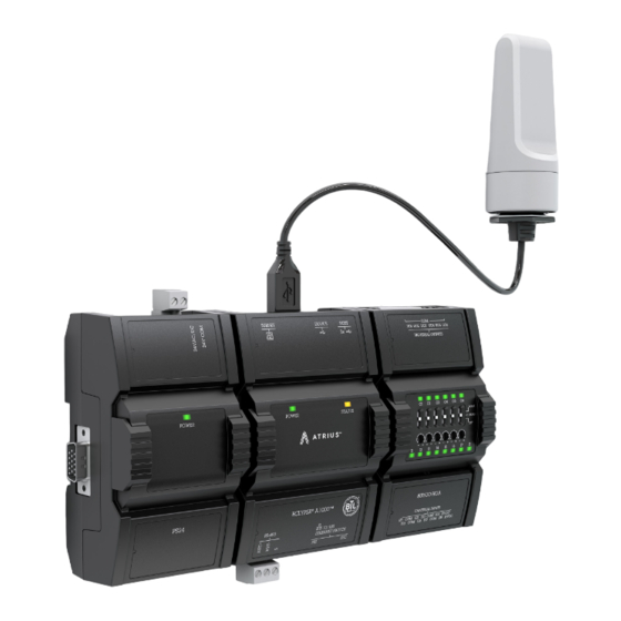
9-0 OPTIONAL WiFi and BLE Adaptor Mounting Instructions 9-1 Typical Mounting Scenarios The ECLYPSE A1000 wireless adaptor is typically mounted in one of three common scenarios, these include: • Suspended Ceiling Mount • Mounting Bracket • Metal Panel/Utility Box Whichever mounting scenario is chosen, the wireless adapter should be 16”... -
Page 14: Location Tips For Eclypse A1000 Using Wireless Adapter
9-0 OPTIONAL WiFi and BLE Adaptor Mounting Instructions - cont’d 9-4 Location Tips for ECLYPSE A1000 using Wireless Adapter When installing the wireless adapter, it is important to ensure that distances and obstructions do not impede transmission. Metallic parts, such as reinforcement in walls, machinery, office furniture, etc.
Need help?
Do you have a question about the ATRIUS ECLYPSE A1000 and is the answer not in the manual?
Questions and answers