Table of Contents
Advertisement
LC&D Operation,
Programming and
Maintenance Manual
Project Name:
Project Location:
Acuity Agency:
Order #:
PO #:
Project ID:
Date:
Controls Tech Support:
1-800-535-2465 - option 1: nLight; option 2: SSI; option 3: Fresco; option 4: Synergy; option 5: LC&D/Bluebox; option 6 ROAM
To preschedule a call with tech support (providing a 4 hour business lead time) go to the following
link:
http://www.acuitybrands.com/resources/schedule-support-request
Additional Technical Literature:
https://www.acuitybrands.com/products/controls/lcd
1
Advertisement
Chapters
Table of Contents

Related Manuals for Acuity Controls GR2400

Summary of Contents for Acuity Controls GR2400
- Page 1 LC&D Operation, Programming and Maintenance Manual Project Name: Project Location: Acuity Agency: Order #: PO #: Project ID: Date: Controls Tech Support: 1-800-535-2465 - option 1: nLight; option 2: SSI; option 3: Fresco; option 4: Synergy; option 5: LC&D/Bluebox; option 6 ROAM To preschedule a call with tech support (providing a 4 hour business lead time) go to the following link: http://www.acuitybrands.com/resources/schedule-support-request...
- Page 2 Table of Contents GR2400 Installation and Operation Manual ................3 GR2400 Basic Programming Guide ..................71 Chelsea Digital Switch Programming Guide ................83 Additional Resources (Product specific user guides, Programming documents, etc) ………103...
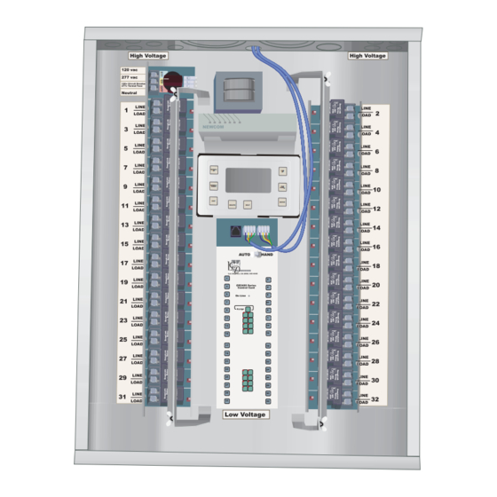
- Page 3 G R 2 4 0 0 M a n u a l www.lightingcontrols.com PCC1 Interface to Photocell On Line On Line Indicator Indicator Factory Entered Address Photocell Los Angeles, CA (800) 345-4448 High Voltage High Voltage 1 0 vac 77 vac 1 0v Circuit Breaker 77v Termal Fuse Neutral...
-
Page 5: Table Of Contents
The GR 2400 Manual Index Programming the GR 2400 System Picture of Programmer Page 25 Navigating the Clock Page 26 The USER Menu Page 27 Quick Start Instructions Review/Changing a Schedule Page 27 Hooking up the GR 2400 System Page 2 Mon to Fri Schedule Page 28 One Line Diagram... - Page 6 The GR 2400 Manual Index (Cont) Addressing Bus Scan Page 40 Auto Addressing Page 41 Appendix II: Start up Check List. Read Address Page 41 Bus Diagnosis Page 41 Pages 58 through 62 Group Loads Menu Page 42 ON/OFFSequencing Page 42 Programming a Sequence Page 43 Specifications...
- Page 7 G G G R R R 2 2 2 4 4 4 0 0 0 0 0 0 M M M A A A N N N U U U A A A L L L How to install the Lighting Control & Design GR 2400 System...
-
Page 8: Hooking Up The Gr 2400 System
Page 2 Outdoor Photocell MODEM Chelsea 6 Digital Switch C C lock Display Quick Start Instructions Hooking up the GR 2400 System The GR 2400 system is very simple to put together. The basic system consists of: 1)The Master Panel like the one on the left, it will have a Clock Display and usually a modem. -
Page 9: One Line Diagram
Relay Panel(s) the data on hand when we ship it. However at start up there are GR2400 PCI usually some minor changes and Indoor Photocell some trouble shooting to be done. If the telephone hook up is avail-... -
Page 10: Typical Panel Schedule
Page 4 Typical Connection GUTTER Most jobs are pre programmed at the factory. You must land the wires from the breakers to the designated relays and connect them to the correct loads for the Relay Panel programming to work! Note: If you use a gutter the neutrals do not need to be sent through or landed in the panel. - Page 11 Page 5 Label Wires Connect Phone Line Write Phone # on Phone Plate Label the line feed wire with the number of the breaker. Use a separate breaker for powering the electronics. This prevents a problem circuit from disabling the whole 1 1 20 Vac system.
- Page 12 Page 6 Make sure the numbered Connect and Terminate the Bus switches are connected at the correct locations as per The “Bus Connectors” are all wired in parallel. Use Cat 5, 4 twisted pair wire. the switch schedules or the 1= (Nominal Ground or Common of System) The Green Pair wired together programming will be incor- 2= (Data Wire “A”) The Orange wire of the Orange White Pair...
- Page 13 Page 7 Connecting up the GR 2400 System. Cable Testers Lighting Control & Design recommends the use of pre- made and pre-tested Ethernet style cables. These can A vital tool to have is a cable tester. even be pulled through conduit with little difficulty. In This ensures that cables are verified most cases the cabling does not have to be in conduit in the field as being hooked up cor-...
- Page 14 Page 8 Typical Hook up of a 2 Panel system with two Switches using Using the “1234" Connectors “1234" Connectors: Panel A LCP 1 Older systems have “1234" Connectors. These Switch 1 Panel B LCP 2 Switch 2 are wired as shown on the left. New systems GR 2404 -DIM use RJ 45 connectors only and the “1234"...
- Page 15 Page 9 LCP 1 LCP 2 Add Gnd & +12 V ONLY Add Gnd & +12 V ONLY 300 ft Example of a Tenant Improvement High Rise Core and Shell. Getting out of trouble The booster wire can be 2 number 18s or just a short section Too Many Switches on a section of Bus of Cat 5 with two pairs twisted together for +12 and two pairs twisted together for Gnd.
- Page 16 Page 10 4000 ft Things to know about the BUS The bus may be up to 4000 ft long. Items must be connected in sequence. No Star Topologies allowed. Note the way the bus has been drawn with an angle in and vertical out. This is the standard way to represent an RS 485 type data bus. RS 485 is a Standard that describes the voltages associated with transmitting data on this type of bus.
- Page 17 Page 11 School Gym and Associated Rooms Bus Length 3500 ft without adding switch in Scorekeeper Sky Box Change to Analog Switch and home run wires to a “DigiLink” 400Ft wire Score Keeper Sky Box Getting Out of Trouble Too Long a Bus The solution was to order an analog switch with a DigiLink In this example of a school Gym the switches and panels dry Contract input card instead of a digital switch for that...
- Page 18 Page 12 Parts of the System: 600 Volt 2 pole relays. These take up two single pole relay spaces and are mechanically linked 2 pole relays. They are used for dual Relays 277Vac circuits that require a higher rating (480Vac) than the standard 277 Vac relays. These relays will be mounted in a special sec- Standard SnapLink Relay...
-
Page 19: Changing Relays
Page 13 Changing Relays Relays are mounted in "Snap Track." This is an insulating holder that allows relays to be "Snapped" in and out. First loosen the mounting screws for the barrier that both acts a clamp and a cooling fin for the relays. Remove the high voltage connections and unplug the low voltage connections. -
Page 20: Dual Voltage Input Card
Page 14 Dual Voltage Input Card Most systems are shipped with dual voltage input cards. These have a rotary switch that selects OFF, 120 VAC or 277 VAC. When 277Vac is connected there will be no voltage on the 120 Volt terminal and similarly when 120 Volts is selected DigiLink there will be no voltage on the 277Vac connector. - Page 21 Page 15 +12V Watt Stopper DT 200 Normally Closed Contact Dry Contact to Energy Management System Common 24 V Normally Open Contact Multiple inputs from an EMS system may be connected with a single common as shown. Normally programmed as Control Output 24Vdc Common (Power) MAINTAINED inputs.
- Page 22 Page 16 GR 2404 S Relay Panel The hard wired ON/OFF inputs may be programmed via the Clock/ Programmer in the RELAY PROPERTIES MENU or The GR 2404s is called a “Micro Panel.” The GR 2404-iDH if requested, in advance, by the factory to be Toggle/Off and GR 2404-iDIM have their own manual.
- Page 23 Page 17 Momentary Digital 4 Off Connector Switch 4 On 3 Off Programmer Jack 3 On Terminator 2 Off 2 On Los Angeles,CA 1 Off 800-345-4448 1 On GR 2404 Control Card + 5 V Clock Inputs on GR 2404 with ON and OFF Zone 1 ON Momentary Push Buttons.
-
Page 24: Board Addressing
L o s A n g e l e s , C A ( 8 0 0 ) 3 4 5 - 4 4 4 8 panel. Zones 1-8 Active GR2400 Series Each output is capable of driving up to 2 relays. In situations where the board is driv- Control Card Zones 9-16... - Page 25 Page 19 a) 8 Zone Mode: In this mode the "Zone Buttons" 1-8 in the first 16 relay section are active while the 9 through 16 are not. (Or it is a 16 relay card and there is no 9 to 16) In the 8 zone mode the relay card takes up 1 address on the bus.
-
Page 26: Gr 2416 Card
Page 20 SCROLL SCROLL "Discrete Mode" LIGHTING CONTROL & DESIGN WITHIN WITHIN WITHIN WITHIN A PAGE A PAGE FIELD FIELD 9:39 am 30 Mar 98 Mon In the Discrete Mode each relay in the panel is visible on SCROLL SCROLL DOWN DOWN DOWN... -
Page 27: Checking The Mode
Page 21 and the next is an OFF etc. Checking the Mode of a GR 2432/48 Card. If you suspect that the Factory Set Mode is not the 4) Zones only operate the relays in that panel. One mode your card is actually in then press and hold cannot assign relays from a second panel to that the "Assign"... -
Page 28: Viewing Which Relays Are In A Zone
Page 22 This speed may be changed from Zero to ninety d) Press the Assign Button again to put this configu- nine 60 Hz cycles. ration into memory. If the Assign button is not pushed within 20 seconds of a relay button being Use the Relay Parameters Menu in the What and pushed the "Assign"... -
Page 29: Flashing Leds What They Mean
If it is flashing slowly but is Mostly ON with a Zones 1-8 “Timer” Mode. The relay will perform Active GR2400 Series flash OFF this means that the board cannot see an automatic shut off usually within Control Card Zones 9-16... -
Page 30: Other Accessory Boards
Page 24 Other Accessory Boards There are several additional boards that need more understanding of how the DTC Clock is programmed in order to fully understand their actions. These include: a) The Photocell Card, 1 and 3 input. b) The LanLink interface. c) The T-Link Thermostat interface. - Page 31 Page 25 Programming the GR 2400 System. SCROLL LIGHTING CONTROL & DESIGN V 2.14a LC & D (800) 345-4448 SCROLL 5.25pm 26 SEPT 2004 Clock DOWN DOWN RS232 for Modem Press any button to start Connector (8 wire or Computer (6 Wire Telephone RJ45) Telephone RJ 12) EXIT...
-
Page 32: Navigating The Clock
Page 26 Navigating the Clock TAB Buttons UP and DOWN are the ones to Scroll Buttons Up use to jump from line to and DOWN line in a menu. Only change the values fields that can be within a field SCROLL LIGHTING CONTROL changed or take you to... -
Page 33: The User Menu
Page 27 The field on the right says UNUSED for schedules that have THE USER MENU not yet been programmed and cannot be entered yet. Once Pressing any key on the opening page display will take you a schedule has been entered this field becomes available to to the USER MENU. -
Page 34: By Day Schedule
Page 28 SCH 5 EXCEPT NONE MONDAY-FRIDAY The default schedule is 9am to 5 pm. This gives fewer but- ON TIME: 09:00am ton pushes to scroll the fields to their correct time in most applications. OFF TIME: 05:00pm SAT ON TIME: 09:00am EXCEPT NONE means that the schedule applies to 365 OFF TIME: 05:00pm days of the year. -
Page 35: After Midnight
Page 29 ON TIME: 09:00:00am OFF TIME: 05:00:00pm Note that this ON time is on Friday ON TIME: 04:00:00pm ACTIVE DAYS: OFF TIME: 4:00:00am SAVE Sat,Sun ACTIVE DAYS: Time to the nearest Second EVERYDAY This schedule allows for setting ON and OFF times to the SAVE nearest second. -
Page 36: Schedules And Groups
Page 30 Disabling Schedules Schedules and Groups Before going on to Groups it is important to know that one Consider that we have just programmed Schedule 5. Exiting may disable a schedule by scrolling on the highlighted out of a schedule takes you back to the SCHEDULES Schedule. -
Page 37: Group Properties
Page 31 Name:LCP 1 MAINTAIN EDIT: LCP-1 LOAD-1 Group Properties The top right field in this screen is the Group Properties. LCP1: 1-3 This describes what the group will do when initiated. A Group may have the following properties : a) MOMENTARY ON. -
Page 38: When To Set The Blink Warning
Page 32 GROUP 5 PARAMETERS MANUAL CONTROL ON= = Load is in Timer LCP-1 LOAD-1 OFF=- Mode AUTOMATIC ON 1- 3- 5- 7- 9- 11- 13- 15- TIMER OUT: 2:00:00 Hr = Load is in Timer 2- 4- 6- 8- 10- 12- 14- 16- Mode and a BLINK BLINK WARNING: 05 min warning has been... -
Page 39: Contacting Lc&D
V 2.14 and Later ENTER NEW TIME/DATE Page 33 SETUP MENU V 2.0 and earlier --------------------------------------- SETUP MENU 11:35:00 am RESTRICTED SYSTEM SETUP MENU RELAY PROPERTIES GROUP LOADS 6 Jul 1999 Tue CONTACTING LC&D PROGRAM SWITCH SYSTEM SETUP MENU RESTRICTED (THERMOSTAT) Time starts when CONTACTING LC &... - Page 40 Page 34 HOLIDAY LIST1 PAGE 3 HOLIDAY LIST1 PAGE 1 1996: New Year: NO Jan 1 1996: M.L.King : NO Jan 1 1996: Presidents: NO Jan 1 1996: March 13th : NO Jan 1 1996: Memorial: NO Jan 1 1996: Independence: NO Pages 3 and 4 of the Holiday list are for custom In the HOLIDAY Menus the Page # should say...
-
Page 41: System Option
Page 35 b) Putting in an incorrect code requires a 60 second wait SYSTEM OPTIONS before trying another code. This can be infuriating even if This leads to a sub menu which has to do with all the you know the code but just mis-keyed it. permanent changes one can make to the system. -
Page 42: Display Options
Page 36 Military Time : DISPLAY OPTIONS Seconds Visible : YES This menu gives a list of options available in the display. Daylight Savings: YES MILITARY TIME will display all time measurement in Mili- Temperature F/C: F tary time. Thus 4.12pm will display as 16:12 Hr. Display Groups: SECONDS VISIBLE defaults to YES. -
Page 43: What And When Menu
Page 37 CHANGINGNAMEOF WHAT and WHEN MENU GROUP 5 SCHEDULED EVENTS WHAT CONTROLS GROUPS ===> GROUP 5 <=== WHAT CONTROLS RELAYS RELAY PROPERTIES SCHEDULED EVENTS Press ENTER on the type of item that is to be named . (Say GROUPS) Tab through until you get the exact item Scheduled events lists the times in order of occurrence (SAY GROUP 5) and then use the scroll up and down keys from all the schedules. -
Page 44: What Controls Groups
Page 38 WHATCONTROLS RELAY PROPERTIES Menu GROUP 5 Hitentertoscan This menu will change the parameters of each of the relays theselectedgroup. on a relay card. RLY PARAMs PAGE 1-1 BOARD 1 BOARD 2 DLY 1 WHAT CONTROLS GROUPS BOARD 3 Scroll to the Group number and then Hit ENTER. -
Page 45: Specifying Normally Closed Relays
Page 39 BOARD 1 SETTINGS 1 2 3 4 5 6 7 8 Note that a GR 2432 card in the "Discreet" mode has 4 Normally Closed addresses associated with it. Only the first address on the -- -- -- -- -- -- -- card has a delay associated with it. - Page 46 Page 40 The value of the Timer is usually set by adding that relay to To prevent such loads from being blinked it is best to tag a Group. Occasionally a board is disconnected when a them as "No Blink" relays. This will prevent them from being Group is erased and the timer will remain active.
-
Page 47: Auto Addressing
Page 41 BUS DIAGNOSTICS The unique serial number of the chip is also displayed. This AUTO ADDRESSING may have relevance in later versions of the clock. READ ADDRESS BUS DIAGNOSIS BUS DIAGNOSIS MENU. This is one of the most useful menus for checking out the system. -
Page 48: On/Offsequencing
Page 42 right now it will eventually cause a problem. Usually it is a A Group that has the parameter of being MNTN + TIMER or bad connection or a broken wire at a switch that was recent- MNTN+OFFSWEEP that is in the OFF state will be receiv- ly moved. -
Page 49: Programming A Sequence
Page 43 PROGRAMMING SWITCHES Programming a Sequence a) Set up a Schedule to turn ON and OFF the Sequence. If Pressing ENTER on PROGRAM SWITCH takes you to the you do not actually need a schedule it can be a dummy Switches Menu. - Page 50 Page 44 Pressing ENTER on a selected Button takes you to the but- e) MAINTAIN. When the button is pushed in the load will ton programming menu. This looks very like the Group pro- turn ON and when the button is released the load will turn gramming menu and works in exactly the same way.
-
Page 51: Additional Features In Clock Version 4.16
Page 45 ADDRESSING BUS SCAN leads FACTORY SETUP MENU Additional Features in Clock version 4.16 to the Bus Diagnostics menu which A A D D D D D D R R R E E E S S S S S S I I I N N N G G G B B B U U U S S S S S S C C C A A A N N N now has additional items. - Page 52 Page 46 BUS DIAGNOSTICS EEPROM FLAG ERROR ERROR STATISTICS leads to the EEPROM WRITE ERROR AUTO ADDRESSING screen below READ ADDRESS These both refer to the memory management within the clock. BUS SCAN DISPLAY If either one of these is not zero the clock must be replaced. ERROR STATISTICS MORE DIAGNOSTICS DROP-OFF: This is the cumulative number of actual drop offs...
- Page 53 Page 47 DROP OFF STATS 1-80 is a read only screen that shows the accumu- lated number of failed “presence requests” by address since the last RESET COUNTS is a vital screen that shows the MORE DIAGNOSTICS CLEAR in the ERROR STATISTICS screen. This screen shows address- number of times each of the control cards and the DEFAULT TO MAIN: Yes es 1-80.
- Page 54 Page 48 Scan by Factory ID MORE DIAGNOSTICS With Collisions Scanning with Collisions DEFAULT TO MAIN: Yes This screen is to verify that there are no TRIGGER: NONE FACTORY ID-SCANNING items on the bus at the same address or DROPOFF STATS 1-80 If the bus comes up with collisions that there are no items on the bus that do DROPOFF STATS 81-127...
- Page 55 Page 49 This is what the Schedules There is another new menu SETUP MENU screen looks like with the first that is not listed in the earlier 4 Schedules disabled over RESTRICTED versions of the manual. This RELAY PROPERTIES the bus and Schedule 1 addi- SYSTEM SETUP MENU is the SCHEDULE PROPER- tionally disabled by scrolling...
- Page 56 Page 50 Photocell Control Cards Photocell Photocells are programmed like switches so they are covered in the Connector switch section. There are two types of control card that are used with NOTE: photocells. The Single and the Three input photocell card. Connections are Polarized Single Input Card...
-
Page 57: Three Input Card
Page 51 PCC3 -Scroll to get: SENSOR ID # 5-1 ANALOG 1 ANALOG 2 Programming Photocells : 0038 Analog 1 ANALOG 3 Time Delay : 5 Mins Photocells are essentially switches that trigger at certain DIGI 1(Enable1 if on Trigger 11) On when light level light levels. -
Page 58: Daylight Harvesting
Page 52 Select "Y" to enable or "N" to disable the level Special Situations of this analog input to be If one is not using a photo-sensor as the analog input or displayed on the one needs a different type of scenerio there are additional initial page. -
Page 59: The Restricted Menu
Page 53 BUS SCAN DISPLAY looks different in the Restricted area. Appendix I . The Restricted Menu While the User Menu version requires 3 errors to show a This Appendix covers the more advanced programming of problem this one counts everything. There is an error coun- ter at the bottom that starts from zero on entering this the system. -
Page 60: Panel Switch Types
Page 54 ADDRESSING ERROR STATISTICS: PAGE 1-19 : 2408 as LCP1 : 2404 as LCP 2 OVERALL: 134 : UNUSED ADR8 : : 2 BTN SWITCH CMD1 : 0 : 6 BTN SWITCH : ANALOG 1 CLEAR : ANALOG 3 through the addresses to find out which address the errors are coming from. -
Page 61: Dial Up Host
Page 55 REMOTE SYSTEM MENU DIAL IN PASSWORD Note 1: If the pass word you typed in is different from the one at the far end it will not connect. In host mode this There is no warning message about this, it will is the required DIAL UP HOST just not connect. -
Page 62: Erase Clock Memory
Page 56 WARNING ! ! ! While on this screen WARNING ! ! ! Pressing the You are about to Address/Erase button ERASE ALL MEMORY ! of any board will erase board memory. Select 'NO' if you are not sure WARNING ! ! ! NO/YES While on this screen... -
Page 63: Changing The Mode On A Gr 2416 Card
Page 57 GR 2416 Card GR 2416 Card Changing the Mode on a GR 2416 Card 5) Push 2) Push As covered earlier in the Manual the GR 1416 card and the GR 2432 or GR 2448 cards may be sent out from the facto- 3) Push ry in one of three different modes. - Page 64 Page 58 Double check the mode one is in by pressing and holding down the ASSIGN button for more than 3 seconds. Appendix II Checklist for GR 2400/1400 System Start Up Next Page...
- Page 65 Page 59 Checklist for GR 2400/1400 System Start Up Appendix II c) Make sure that the system is NOT POWERED. There 1) Verify that the system is complete against the bill of should not be any power on any control card. Having veri- materials.
- Page 66 Page 60 Typical problems that this measurement shows up are: about 12 volts + or - 1.5 volts. Do not plug in the bus yet. i) 3000ft of wire was used on the job yet the bus measures 83 ohms. This shows an extra terminator some place on the b) Fire up all the other panels that do not have clocks in the bus or that the first terminator was not removed for the test.
- Page 67 Page 61 3303000000 1110000000 Tab down to clear and press ENTER. Then watch the dis- 0000000000 0000000000 play for a couple of minutes. If the error count starts rising 0000000000 0000000000 then highlight the address line as shown and scroll up the 0000000000 0000000000 address numbers to see which address is giving the errors.
- Page 68 Page 62 want the light to stay ON.) Make sure that they know Wires next to high voltage with dimmers or where the switches are. electronic ballasts are particularly susceptible to noise Also instruct them on how to use the Manual override switch on the cards to turn ON the system in event of cat- DigiLink cards with analog switches can pick up noise from astrophic failure.
- Page 69 Page 63 Snaplink SoftStart Relay GR 2400 Series Specifications: 120Vac at 20 amps Ballast and Dimensions: Tungsten 32 Relays : 25.5" High, 20" Wide, 6" Deep Rated 100,000 Throws Brings on 48 Relays : 37.5" High, 20" Wide, 6" Deep load to 1/3 power for approx 1/3 Enclosure: Nema 1 Surface or Flush...
- Page 70 Warranty Lighting Control & Design Inc. warrants each new unit for 36 months from date of shipment to be free of defects in material and workmanship under conditions of normal use and specified ambient temperature when installed and operated under LC & D's product specifications and in accordance with the National Electrical Code.
- Page 71 GR 2400 BASIC PROGRAMMING GUIDE Programming Guide Index Introduction . . . . . . . . . . . . . . . . . . . . . . . . . . . . . . . . . . . 2 Navigation Basics .
- Page 72 INTRODUCTION Introduction: Almost all of the devices in the GR The DTC (Digital Time Clock): Most 2400 Lighting Control System are digital, meaning programming is done from the DTC Clock (shown they are part of a peer-to-peer network and can below)/Programmer located in the master be programmed .
- Page 73 NAVIGATION BASICS Menu: “Select a Switch” SWITCHES PAGE 1-2 #33: Reception Tabbing: Use the TAB #52: Master Sw 1 buttons to move around the #53: Master Sw 2 display: #59: Master Sw 3 #61: Hallway 100 #61: Hallway 200 #61: Hallway 220 DOWN to position the cursor .
- Page 74 PROGRAMMING A DIGITAL SWITCH To Start: USER MENU 1. TAB to start. MANUAL OVERRIDE 2. TAB to Program Switch. REVIEW SCHEDULE 3. ENTER to select. GROUP LOADS PROGRAM SWITCH PROGRAM SWITCH SETUP MENU This indicates page 1 of 2: For Multiple Pages: SWITCHES PAGE 1-2 PAGE 1-2...
- Page 75 ADDING OR DELETING LOADS Adding or deleting loads from a switch, MAINTAIN SWI ID63-1 MAINTAIN photocell, time schedule or group is always EDIT: LCP-1 LOAD-1 done in the same way . Once you have Indicates Control Type* navigated to the correct Button, Trigger or Group and before you add or delete loads, it is (Refer to page 10 important to determine the Control Type .*...
- Page 76 BASIC PHOTOCELL SETTINGS To Start: USER MENU 1 . TAB to start . MANUAL OVERRIDE 2 . TAB to Program Switch . REVIEW SCHEDULE 3 . ENTER to select . GROUP LOADS PROGRAM SWITCH PROGRAM SWITCH SETUP MENU For Multiple Pages: (more than 7 switches) SWITCHES PAGE 1-2 PAGE 1-2...
- Page 77 BASIC PHOTOCELL SETTINGS (cont’d) To Program a Trigger Level: SENSOR ID#64-1 “Analog” followed Photocell Cards come with one or three by an integer (1, Analog 1: Analog 1: 0050 photocell inputs . Any of those photocells may 2, 3) indicates this Time Delay: TEST 5 Sec be used to control the Trigger .
- Page 78 EDITING TIME SCHEDULES To Start: USER MENU 1 . TAB to start . MANUAL OVERRIDE 2 . TAB to REVIEW SCHEDULE . REVIEW SCHEDULE REVIEW SCHEDULE 3 . ENTER to select . GROUP LOADS PROGRAM SWITCH SETUP MENU This indicates page 1 of 6 .
- Page 79 SCHEDULE TYPES & TRIGGER EVENTS 1 . SCROLL to the desired schedule type . SCH 1 EXCEPT NONE EVERY DAY EVERY DAY Every Day (7-day schedule): Schedule Type: TIME: 09:00 AM 1 . TAB to ON TIME and SCROLL to select Trigger •...
- Page 80 CONTROL TYPES & GROUP TYPES Control Types: ”Control Types” describes how loads are controlled . TOGGLE Toggle up to 8 loads On or Off . ON MODE Up to 8 loads On only . OFF MODE Up to 8 loads Off only . Also known as an “interlock”—this turns one set of loads On and MIXED MODE another set of loads Off .
- Page 81 PROGRAMMING GROUPS To Access the Group: USER MENU Within the DTC, there are two paths you can use MANUAL OVERRIDE to access a group for programming purposes: REVIEW SCHEDULE A) From USER MENU: GROUP LOADS GROUP LOADS PROGRAM SWITCH 1 . TAB to start . 2 .
- Page 82 Lighting Control & Design 9144 Deering Ave ., Chatsworth, CA 91311 www .lightingcontrols .com © 2007, 2009, 2010 Acuity Brands Lighting Inc., All Rights Reserved. • Form No. 1382.017 994-004-0022...
- Page 83 CHELSEA DIGITAL SWITCH ADVANCED PROGRAMMING GUIDE...
- Page 84 CONTENTS 1. Overview…………………………………………………………………… Page 1 2. Important Programming Notes …………………………………………….. Page 2 3. The Switch Setup Screen (First Screen) …………………………………….Page 3 a. 7 On = ______ …………………………………………………….. Page 4 b. 8 On = ______ ………………………………………………….…. Page 5 c. BTN Beep …………………………………………………….……. Page 6 d.
-
Page 85: Overview
Overview The Chelsea Digital Switch has been updated with several new programmable features. In summary, they are: Programmable Locator LED. Now the LED at the top of • the switch can be programmed to flash during a blink warning. It can also be activated by Tech Support, for use in helping the user identify a particular switch. -
Page 86: Important Programming Notes
Important Programming Notes To use the advanced features of the new Chelsea Digital Switch, please ensure the following: • Always set a Chelsea Digital Switch as a “14 Button Switch” in the Panel/Switch Types screen. This is true even if the switch only has 1, 2 or 3 physical buttons. The reason for this is because advanced programming requires setting parameters for buttons 7-14, even though they are “virtual”... -
Page 87: The Switch Setup Screen (First Screen)
The Switch Setup Screen (First Screen) To access the screen, navigate to the switch you want to program, highlight the word SETUP and press ENTER. USER MENU → PROGRAM SWITCH → SWITCH# → SETUP The Switch Setup Screen has a number of parameters which can be set as shown below. - Page 88 Table 1.1 7 ON = _____________ This field determines what happens when the LED status light associated with Button 7 is turned ON. Generally if the button is set to ON MODE and the relay it controls is ON, the LED will turn ON as well. This also applies to the opposite mode: if the button is set to OFF MODE and the relay it controls is OFF, the LED will also generally turn ON (the only exceptions are if the logic of the Status LEDs are changed as described later in this guide).
- Page 89 Table 1.2 8 ON = _____________ This field determines what happens when the LED status light associated with Button 8 is turned ON. The operation of this field is almost identical in operation to the “7 ON = __”. The parameters are the same as those given in Table 1.1 above with a few exceptions noted below.
-
Page 90: Btn Beep
Table 1.3 BTN Beep This field determines when the switch’s buttons will cause a beeping sound. Possible Values Result There will never be a beeping sound when a button is pressed. Note that any beep alerts set to take place using the “7 On = _____”... -
Page 91: 9-14 Disable
Table 1.5 9-14 disable 1-6 Determines whether “virtual” buttons 9-14 can be used to disable buttons 1-6 on the physical switch. For example, if virtual Button 9 is set to turn on relay X, then any time relay X is ON, the physical Button 1 will be disabled. If relay X is OFF, then Button 1 will function normally. - Page 92 Selectable value These are global values that apply to all of the switch’s between 0.05 sec buttons. Whatever value is selected will be how long the and 5.00 sec. user must hold down the button before its programming is activated. For example, setting the value to 2.00 sec means that when the user first presses a button on the switch, nothing will happen.
-
Page 93: The Switch Setup Screen (Second Screen)
The Switch Setup Screen (Second Screen) The Switch Setup Screen has additional parameters shown on a second page in the DTC screen. Along with the Debounce option on the first screen, these parameters are global in that they override any local LED logic set in the EDIT menu and apply to all buttons on a switch. -
Page 94: Led Logic For Other Buttons
Table 2.2 LED logic for other buttons Sets the logic which determines if the Status LED over each of the switch’s buttons should be on or off. This field applies to buttons in TOGGLE MODE, ON MODE, MAINTAIN, MIX MODE (all other settings except OFF MODE). Possible Values Result The Status LED on a button will light up only if ALL the... -
Page 95: The Button Edit Screen
The Button Edit Screen To access the Button EDIT screen, navigate to the switch button you want to program, highlight the word EDIT and press ENTER. These parameters are local, meaning that they apply to each individual button only, not the entire switch. USER MENU →... -
Page 96: Toggle Mode
Table 3.2 Toggle mode Sets how the button synchronizes multiple relays when toggling. For example, if a switch button is toggling relay X, relay Y and relay Z, the user can decide what happens when relay Y is ON and relays X and Z are OFF. The least desirable behavior is to have the relays just flip states so that no matter how the TOGGLE button is pressed either, relay Y is OFF and relays X and Z are ON, or relay Y is ON and relays X and Z are OFF. -
Page 97: Common Applications
Common Applications Question: How do I disable a particular switch button (for example, button 3)? Answer: 1. Go to the Program Switch screen and select the switch you want to disable the button for. For physical Button 3, you would use the virtual Button 11 to enable and disable it. -
Page 98: How Do I Set A Button To Give An Audible "Error" Beep When Someone Presses A Disabled Button
Question: How do I set a button to give an audible “error” beep when someone presses a disabled button? Answer: It can be very frustrating or confusing to a user when they press a button that usually turns certain lights on and off, only to find that nothing is happening. Sometimes, this happens when a switch button has been programmed to be disabled, but the user has no way of knowing. -
Page 99: How Do I Make A Switch Give An Audible Alert During A Blink Warning Period
Question: How do I make a switch give an audible alert during a blink warning period? Answer: It is a fairly common request to have users notified a few minutes before the lights turn off, so they have an opportunity to override the offsweep. Instead of having the lights flash, or a separate horn installed, the new switch can be set to generate a beeping alert pattern as a warning that the lights will be shutting off shortly. - Page 100 9. That’s it. Now, at the end of the schedule, the switch will start beeping to signal that the lights will be shutting off shortly. If the user presses the override button on the switch, the beep alert will stop, and the lights will stay on for an additional 2 hours (or whatever duration the Timer was set to in the Maintain+Blink Group).
-
Page 101: How Do I Set Up A Room With A Partition, So That The Switches Change Their Function Depending On Whether The Partition Is Open Or Closed
Question: How do I set up a room with a partition, so that the switches change their function depending on whether the partition is open or closed? Answer: Let’s take a scenario where a room has a switch on the north wall, a switch on the south wall, and a partition that can separate the room into a north half and a south half. - Page 102 1. For the North Switch, program Button 1 to ON MODE for Relay 1 and Relay 2. Program Button 2 to OFF MODE for Relay 1 and Relay 2. 2. While still in the Program Switch screen for the North Switch, set Button 9 to ON MODE for Relay 1 only.
- Page 103 Wireless Switch Installation Guide xCella Wireless Keycard Installation Guide xCella Lamp Control Module Installation Guide xCella Door/Window Sensor Installation Guide xCella Ceiling Occ Installation Guide Link-To™ DMX Manual Programming Guides GR2400™ Final Activation Checklist Software Guides Unity GX2™ Customer Submission Guide...