Table of Contents
Advertisement
Quick Links
Owner's Manual
NOTE
TO INSTALLER:
THIS
MANUAL
MUST
BE LEFT
WITH
THE
EQUIPMENT
USER.
USER:
PLEASE
READ
ALL
INSTRUCTIONS
IN THE MANUAL
AND
RETAIN
ALL
MANUALS
FOR
FUTURE
REFERENCE.
FIRE OR EXPLOSION
HAZARD
Failure
to follow
warnings
could
result
in personal
iniury , death, or property
damage.
Do not store or use gasoline
or other flammable
vapors
and liquids in the vicinity
of this or any other appliance.
WHAT
TO DO IF YOU SMELL
GAS
-Do not try to light any appliance.
-Do
not touch
any electrical
switch;
do not use any
phone in your building.
-Leave
the building
immediately.
-Immediately
call your
gas
supplier
from
a nearby
phone.
Follow the gas supplier's
instructions.
-If you cannot reach your gas supplier,
call the fire
department.
Installation
and
service
must
be
performed
by
a
qualified
installer,
service agency or the gas supplier.
Al1263
CARBON
MONOXIDE
POISONING
HAZARD
Failure to follow this warning could result in personal injury
and/or death.
Carbon Monoxide is invisible, odorless, and toxic! Install a
carbon monoxide alarm in your home, even if you do not
own a gas appliance. Locate the carbon monoxide alarm in
the living area of your home and away from gas appliances
and
doorways
to attached
garages.
Follow
the alarm
manufacturer's
instruction included with the alarm.
ELECTRICAL
OPERATION
HAZARD
Failure to follow this warning could result in personal injury,
death, or property damage.
Do not use this furnace if any part has been under water. A
flood-damaged
furnace is extremely dangerous. Attempts to
use the furnace can result in fire or explosion. A qualified
service agency should be contacted to inspect the furnace and
to replace all gas controls, control system parts, and electrical
parts that have been wet, or the entire furnace if deemed
necessary.
Advertisement
Table of Contents

Related Manuals for Carrier Furnace


Summary of Contents for Carrier Furnace
- Page 1 HAZARD Failure to follow this warning could result in personal injury, death, or property damage. Do not use this furnace if any part has been under water. A flood-damaged use the furnace can result in fire or explosion. A qualified...
- Page 2 * The output capacity and any representations of efficiency for this furnace are based on standard U.S. Department of Energy costs, a 90+% AFUE...
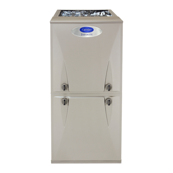
- Page 3 REPRESENTATIVE DRAWING ONLY, SOME MODELS MAY VARY IN APPEARANCE. FURNACE COMPONENTS position; be used in downflow or horizontal HOT SURFACE IGNITER MANUAL GAS BURNER ROLLOUT Fig. 1 - Furnace Components orientation or applications. RESET SWITCH MAIN LIMIT SWITCH (BEHIND GAS VALVE) INDUCER MOTOR ASSEMBLY...
-
Page 4: Safety Considerations
• Your new gas furnace may have been installed in one of two ways, as a direct-vent (2-pipe-Fig. 2) application non-direct vent (l-pipe-Fig. 3) application. • In a direct-vent (2-pipe) -
Page 5: Before Starting Your Furnace
Fig. 4 - NO combustible materials near furnace • Do not cover the furnace, store trash or debris near it, or in any way block the flow of fresh air to the unit. []NIT... - Page 6 • CHECK AIR FILTER: Before attempting to start your furnace, be sure the furnace filter is clean and in place. See "Perfornfing Routine Maintenance" manual. Do not run the furnace without...
- Page 7 After the hot surface igniter is heated for about 20 seconds, the Al1291 gas valve pernfits to ON tion and a time delay of up to 60 sec, the furnace blower start. control makes the necessary at either the low- or high-heat...
-
Page 8: Routine Maintenance
FURNACE service off. The following temperature setting 6. Replace 7. If the furnace is being shut down because of a malfunction, your dealer as soon as possible. []NIT AND PROPERTY A09564 Setting Failure to follow this caution may result in unit component or property damage. -
Page 9: Cut Hazard
5. Reinstall clean air filter. 6. Turn on electrical supply to the furnace. If your furnace air filter needs to be replaced, be sure to use a factory-authorized specified. Use the filter tables and compare your furnace size with the proper filter size. - Page 10 Fig. 22 - Removal of Filter Cabinet Door Blower Cabinet Fig. 23 - Removal of Filter from Side Fig. 26 - Replacement FILTER CABINET HEIGHT IN (MM) 16 (406) 20 (508) 24 (610) Filters with a side return-air may have a different filter size. Measure the filter to obtain the correct size. Recommended to maintain air filter face velocity.
-
Page 11: Air And Vent System
Hori- zontal portions of vent pipe must slope downward toward the furnace. 4. If your furnace is free of the above conditions turn on elec- by an trical and gas supplies to the furnace. - Page 12 AND PROPERTY DAMAGE HAZARD Failure to follow this caution may result in unit component property damage. If the furnace is installed in an unconditioned ambient temperatures may be 32 ° F (0 ° C) or lower, freeze protection measures must be taken to prevent or product damage.
- Page 13 • Inspect all combustion-air and vent piping inside structure and pipe terminations outside the structure. • Check gas pipes leading to and inside of your furnace for leaks. • Inspect and clean the blower motor and wheel. NOTE: The inducer and blower motors are pre-lubricated require no additional lubrication.
- Page 14 Serial # INDOOR COIL (Furnace Coil or Fan Coil) Model # Serial # Copyright 2011 Carrier Corp. • 7310 W. Morris St. • Indianapolis, Manufacturer reserve8 the right to change, at any time, specification8 NOTE TO EQUIPMENT along with the installation data and dealer contact or service.
-
Page 15: Operation
HAZARD Failure to follow this warning could result in personal injury, death, or property damage. Do not use this furnace if any part has been under water. A flood-damaged use the furnace can result in fire or explosion. A qualified... - Page 16 * The output capacity and any representations of efficiency for this furnace are based on standard U.S. Department of Energy costs, a 90+% AFUE...
- Page 17 REPRESENTATIVE DRAWING ONLY, SOME MODELS MAY VARY IN APPEARANCE. FURNACE COMPONENTS position; be used in downflow or horizontal HOT SURFACE IGNITER MANUAL GAS BURNER ROLLOUT Fig. 1 - Furnace Components orientation or applications. RESET SWITCH MAIN LIMIT SWITCH (BEHIND GAS VALVE) INDUCER MOTOR ASSEMBLY...
-
Page 18: Safety Considerations
• Your new gas furnace may have been installed in one of two ways, as a direct-vent (2-pipe-Fig. 2) application non-direct vent (l-pipe-Fig. 3) application. • In a direct-vent (2-pipe) -
Page 19: Before Starting Your Furnace
Fig. 4 - NO combustible materials near furnace • Do not cover the furnace, store trash or debris near it, or in any way block the flow of fresh air to the unit. []NIT... - Page 20 • CHECK AIR FILTER: Before attempting to start your furnace, be sure the furnace filter is clean and in place. See "Perfornfing Routine Maintenance" manual. Do not run the furnace without...
- Page 21 After the hot surface igniter is heated for about 20 seconds, the Al1291 gas valve pernfits to ON tion and a time delay of up to 60 sec, the furnace blower start. control makes the necessary at either the low- or high-heat...
-
Page 22: Routine Maintenance
FURNACE service off. The following temperature setting 6. Replace 7. If the furnace is being shut down because of a malfunction, your dealer as soon as possible. []NIT AND PROPERTY A09564 Setting Failure to follow this caution may result in unit component or property damage. -
Page 23: Cut Hazard
5. Reinstall clean air filter. 6. Turn on electrical supply to the furnace. If your furnace air filter needs to be replaced, be sure to use a factory-authorized specified. Use the filter tables and compare your furnace size with the proper filter size. - Page 24 Fig. 22 - Removal of Filter Cabinet Door Blower Cabinet Fig. 23 - Removal of Filter from Side Fig. 26 - Replacement FILTER CABINET HEIGHT IN (MM) 16 (406) 20 (508) 24 (610) Filters with a side return-air may have a different filter size. Measure the filter to obtain the correct size. Recommended to maintain air filter face velocity.
-
Page 25: Air And Vent System
Hori- zontal portions of vent pipe must slope downward toward the furnace. 4. If your furnace is free of the above conditions turn on elec- by an trical and gas supplies to the furnace. - Page 26 AND PROPERTY DAMAGE HAZARD Failure to follow this caution may result in unit component property damage. If the furnace is installed in an unconditioned ambient temperatures may be 32 ° F (0 ° C) or lower, freeze protection measures must be taken to prevent or product damage.
- Page 27 • Inspect all combustion-air and vent piping inside structure and pipe terminations outside the structure. • Check gas pipes leading to and inside of your furnace for leaks. • Inspect and clean the blower motor and wheel. NOTE: The inducer and blower motors are pre-lubricated require no additional lubrication.
- Page 28 Serial # INDOOR COIL (Furnace Coil or Fan Coil) Model # Serial # Copyright 2011 Carrier Corp. • 7310 W. Morris St. • Indianapolis, Manufacturer reserve8 the right to change, at any time, specification8 NOTE TO EQUIPMENT along with the installation data and dealer contact or service.
-
Page 29: Operation
HAZARD Failure to follow this warning could result in personal injury, death, or property damage. Do not use this furnace if any part has been under water. A flood-damaged use the furnace can result in fire or explosion. A qualified... - Page 30 * The output capacity and any representations of efficiency for this furnace are based on standard U.S. Department of Energy costs, a 90+% AFUE...
- Page 31 REPRESENTATIVE DRAWING ONLY, SOME MODELS MAY VARY IN APPEARANCE. FURNACE COMPONENTS position; be used in downflow or horizontal HOT SURFACE IGNITER MANUAL GAS BURNER ROLLOUT Fig. 1 - Furnace Components orientation or applications. RESET SWITCH MAIN LIMIT SWITCH (BEHIND GAS VALVE) INDUCER MOTOR ASSEMBLY...
-
Page 32: Safety Considerations
• Your new gas furnace may have been installed in one of two ways, as a direct-vent (2-pipe-Fig. 2) application non-direct vent (l-pipe-Fig. 3) application. • In a direct-vent (2-pipe) -
Page 33: Before Starting Your Furnace
Fig. 4 - NO combustible materials near furnace • Do not cover the furnace, store trash or debris near it, or in any way block the flow of fresh air to the unit. []NIT... - Page 34 • CHECK AIR FILTER: Before attempting to start your furnace, be sure the furnace filter is clean and in place. See "Perfornfing Routine Maintenance" manual. Do not run the furnace without...
- Page 35 After the hot surface igniter is heated for about 20 seconds, the Al1291 gas valve pernfits to ON tion and a time delay of up to 60 sec, the furnace blower start. control makes the necessary at either the low- or high-heat...
-
Page 36: Routine Maintenance
FURNACE service off. The following temperature setting 6. Replace 7. If the furnace is being shut down because of a malfunction, your dealer as soon as possible. []NIT AND PROPERTY A09564 Setting Failure to follow this caution may result in unit component or property damage. -
Page 37: Cut Hazard
5. Reinstall clean air filter. 6. Turn on electrical supply to the furnace. If your furnace air filter needs to be replaced, be sure to use a factory-authorized specified. Use the filter tables and compare your furnace size with the proper filter size. - Page 38 Fig. 22 - Removal of Filter Cabinet Door Blower Cabinet Fig. 23 - Removal of Filter from Side Fig. 26 - Replacement FILTER CABINET HEIGHT IN (MM) 16 (406) 20 (508) 24 (610) Filters with a side return-air may have a different filter size. Measure the filter to obtain the correct size. Recommended to maintain air filter face velocity.
-
Page 39: Air And Vent System
Hori- zontal portions of vent pipe must slope downward toward the furnace. 4. If your furnace is free of the above conditions turn on elec- by an trical and gas supplies to the furnace. - Page 40 AND PROPERTY DAMAGE HAZARD Failure to follow this caution may result in unit component property damage. If the furnace is installed in an unconditioned ambient temperatures may be 32 ° F (0 ° C) or lower, freeze protection measures must be taken to prevent or product damage.
- Page 41 • Inspect all combustion-air and vent piping inside structure and pipe terminations outside the structure. • Check gas pipes leading to and inside of your furnace for leaks. • Inspect and clean the blower motor and wheel. NOTE: The inducer and blower motors are pre-lubricated require no additional lubrication.
- Page 42 Serial # INDOOR COIL (Furnace Coil or Fan Coil) Model # Serial # Copyright 2011 Carrier Corp. • 7310 W. Morris St. • Indianapolis, Manufacturer reserve8 the right to change, at any time, specification8 NOTE TO EQUIPMENT along with the installation data and dealer contact or service.
- Page 43 HAZARD Failure to follow this warning could result in personal injury, death, or property damage. Do not use this furnace if any part has been under water. A flood-damaged use the furnace can result in fire or explosion. A qualified...
- Page 44 * The output capacity and any representations of efficiency for this furnace are based on standard U.S. Department of Energy costs, a 90+% AFUE...
- Page 45 REPRESENTATIVE DRAWING ONLY, SOME MODELS MAY VARY IN APPEARANCE. FURNACE COMPONENTS position; be used in downflow or horizontal HOT SURFACE IGNITER MANUAL GAS BURNER ROLLOUT Fig. 1 - Furnace Components orientation or applications. RESET SWITCH MAIN LIMIT SWITCH (BEHIND GAS VALVE) INDUCER MOTOR ASSEMBLY...
- Page 46 • Your new gas furnace may have been installed in one of two ways, as a direct-vent (2-pipe-Fig. 2) application non-direct vent (l-pipe-Fig. 3) application. • In a direct-vent (2-pipe)
- Page 47 Fig. 4 - NO combustible materials near furnace • Do not cover the furnace, store trash or debris near it, or in any way block the flow of fresh air to the unit. []NIT...
- Page 48 • CHECK AIR FILTER: Before attempting to start your furnace, be sure the furnace filter is clean and in place. See "Perfornfing Routine Maintenance" manual. Do not run the furnace without...
- Page 49 After the hot surface igniter is heated for about 20 seconds, the Al1291 gas valve pernfits to ON tion and a time delay of up to 60 sec, the furnace blower start. control makes the necessary at either the low- or high-heat...
- Page 50 FURNACE service off. The following temperature setting 6. Replace 7. If the furnace is being shut down because of a malfunction, your dealer as soon as possible. []NIT AND PROPERTY A09564 Setting Failure to follow this caution may result in unit component or property damage.
- Page 51 5. Reinstall clean air filter. 6. Turn on electrical supply to the furnace. If your furnace air filter needs to be replaced, be sure to use a factory-authorized specified. Use the filter tables and compare your furnace size with the proper filter size.
- Page 52 Fig. 22 - Removal of Filter Cabinet Door Blower Cabinet Fig. 23 - Removal of Filter from Side Fig. 26 - Replacement FILTER CABINET HEIGHT IN (MM) 16 (406) 20 (508) 24 (610) Filters with a side return-air may have a different filter size. Measure the filter to obtain the correct size. Recommended to maintain air filter face velocity.
- Page 53 Hori- zontal portions of vent pipe must slope downward toward the furnace. 4. If your furnace is free of the above conditions turn on elec- by an trical and gas supplies to the furnace.
- Page 54 AND PROPERTY DAMAGE HAZARD Failure to follow this caution may result in unit component property damage. If the furnace is installed in an unconditioned ambient temperatures may be 32 ° F (0 ° C) or lower, freeze protection measures must be taken to prevent or product damage.
- Page 55 • Inspect all combustion-air and vent piping inside structure and pipe terminations outside the structure. • Check gas pipes leading to and inside of your furnace for leaks. • Inspect and clean the blower motor and wheel. NOTE: The inducer and blower motors are pre-lubricated require no additional lubrication.
- Page 56 Serial # INDOOR COIL (Furnace Coil or Fan Coil) Model # Serial # Copyright 2011 Carrier Corp. • 7310 W. Morris St. • Indianapolis, Manufacturer reserve8 the right to change, at any time, specification8 NOTE TO EQUIPMENT along with the installation data and dealer contact or service.
Need help?
Do you have a question about the Furnace and is the answer not in the manual?
Questions and answers