
Related Manuals for AXIOMATIC AX130511


Summary of Contents for AXIOMATIC AX130511
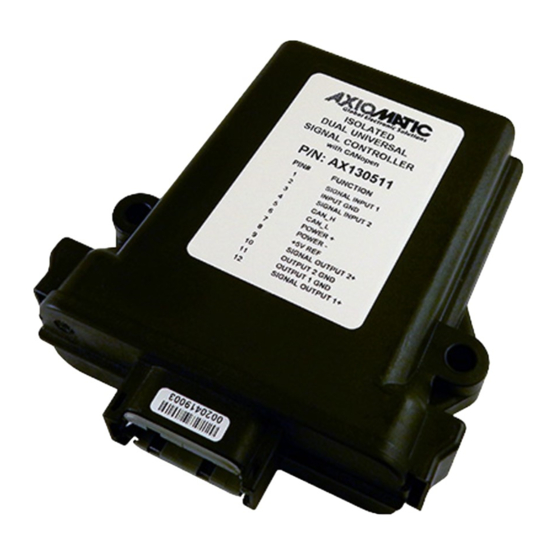
- Page 1 USER MANUAL UMAX130511 DUAL CHANNEL UNIVERSAL SIGNAL CONTROLLER With CANopen® USER MANUAL P/N: AX130511...
- Page 2 VERSION HISTORY Version Date Author Modofication 1.00. Sep 2, 2021 Ilona Korpelainen Initial Draft 1.00A Sep 15, 2021 Ilona Korpelainen Updated to match firmware Dec. 20, Amanda Wilkins Updated dimensional drawing 2021 Preliminary Documentation – May be subject to change UMAX130511 Version 1.00A...
- Page 3 ACRONYMS BATT +/- Battery positive (a.k.a. Vps) or Battery Negative (a.k.a. GND) Control Area Network CANopen ® CANopen ® is a registered community trademark of CAN in Automation e.V. CAN-ID CAN 11-bit Identifier Communication Object CTRL Control Electronic Data Sheet EMCY Emergency Ground reference (a.k.a.
-
Page 4: Table Of Contents
TABLE OF CONTENTS OVERVIEW OF CONTROLLER ..........................12 1.1. Digital Function Block ............................15 1.2. Input Function Block ............................16 1.3. Digital Output Function Block .......................... 22 1.4. Analog Output Function Block ......................... 24 1.5. Internal Function Block Control Source ......................29 1.6. - Page 5 2.3.3. Object 7100h: AI Input Field Value ......................70 2.3.4. Object 6110h: AI Sensor Type ........................ 70 2.3.5. Object 6112h: AI Operating Mode ......................71 2.3.6. Object 7120h: AI Input Scaling 1 FV ....................... 71 2.3.7. Object 7121h: AI Input Scaling 1 PV ....................... 72 2.3.8.
- Page 6 2.4.6. Object 2110h: AI Error Detect Enable ..................... 92 2.4.7. Object 2111h: AI Error Clear Hysteresis ....................93 2.4.8. Object 2112h: AI Error Reaction Delay ....................93 2.4.9. Object 2224h: DO Delay Time 1 Output Line ..................94 2.4.10. Object 2225h: DO Delay Polarity 1 Output Line ..................95 2.4.11.
- Page 7 2.4.46. Object 3yz0h: LTyz Input X-Axis Source ....................114 2.4.47. Object 3yz1h: LTyz Input X-Axis Number ....................115 2.4.48. Object 3yz2h: LTyz Auto Repeat ......................115 2.4.49. Object 3yz3h: LTyz X-Axis Decimal Digits PV ..................116 2.4.50. Object 3yz4h: LTyz Y-Axis Decimal Digits PV ..................116 2.4.51.
- Page 8 2.4.86. Object 5051h: FD Error Response Delay ....................136 2.4.87. Object 5550h: Enable Automatic Updates ..................... 136 2.4.88. Object 5555h: Start in Operational Mode ....................137 APPENDIX A - TECHNICAL SPECIFICATION ......................A-1 Preliminary Documentation – May be subject to change UMAX130511 Version 1.00A viii...
- Page 9 Table 1 – DI Pullup/Down Options ..........................15 Table 2 – Object 6002h DI Polarity 8 Input Lines Options ....................16 Table 3 – Object 6112h - AI Operating Mode Options ....................17 Table 4 – Object 6110h - AI Sensor Type Options ......................17 Table 5 –...
- Page 10 Figure 19 – Logic Block Flowchart ..........................39 Figure 20 – Math Function Block Objects ........................43 Figure 21 – Miscellaneous Objects ..........................45 Figure 22 – Inching Function Block Objetcs ........................47 Preliminary Documentation – May be subject to change UMAX130511 Version 1.00A...
- Page 11 REFERENCES CiA DS-301 V4.1 – CANopen Application Layer and Communication Profile. [DS-301] CAN in Automation 2005 CiA DS-305 V2.0 – Layer Setting Service (LSS) and Protocols. CAN in [DS-305] Automation 2006 CiA DS-404 V1.2 – CANopen profile for Measurement Devices and Closed [DS-404] Loop Controllers.
-
Page 12: Overview Of Controller
1. OVERVIEW OF CONTROLLER The Dual Channel Universal Signal Controller with CANopen ® (2IN-2OUT-SIG-CO) is designed for extremely versatile control of up to two signal level outputs. The controller is widely configurable through CANopen ® Objects. Its flexible circuit design gives the user a large range of configurable input and output types. - Page 13 The controller is four way isolated. Power supply input is galvanic-isolated from bias power supplies. Universal inputs are digitally isolated from universal outputs and CAN Bus. Each isolation section is provided with individual ground. 5V Reference is provided from input section. Logical (software) function blocks are depicted in Figure 2.
- Page 14 Figure 2 – Logic Functional Block Diagram Preliminary Documentation – May be subject to change UMAX130511 Version 1.00A 14 - 141...
-
Page 15: Digital Function Block
1.1. Digital Function Block The digital input (DI) function block only becomes applicable on the input when object 6112h, AI Operation, is set to a digital input response. Figure 3 – Digital Input Objects When object 6112h is set to 10 = Digital Input, object 2020h DI Pull-up/Pull-down Mode will determine the configuration of the internal Pull-up/Pull-down resistors. -
Page 16: Input Function Block
Normal On/Off Inverse On/Off Table 2 – Object 6002h DI Polarity 8 Input Lines Options The format to write to object 6002h is as follows: Sub-index 1 will determine the following inputs polarities Bit 7 Bit 6 Bit 5 Bit 4 Bit 3 Bit 2 Bit 1 Bit 0 The rest of the bits in sub-index 1 will be ignored. - Page 17 Figure 6 – Analog Input Objects Object 6112h, AI Operating Mode determines whether the AI or DI block is associated with an input. The options for object 6112h are shown in Table 3. No values other than what are shown here will be accepted.
- Page 18 changed. The grayed cells mean that the associate value is not allowed for the range object when that sensor type has been selected. Value Voltage Current Frequency Resistive 20 Ω to 250 kΩ 0 to 5V 0 to 20mA 0.5Hz to 50Hz Low Freq (<1kHz) 0 to 10V 4 to 20mA...
- Page 19 Table 7 – Object 61A0h - AI Filter Type Options Object 61A1h AI Filter Constant is used with all three types of filters as per the formulas below: Calculation with no filter: Value = Input The data is simply a ‘snapshot’ of the latest value measured by the ADC or timer. Equation 1 - Moving Average Transfer Function: ( Input- Value Value...
- Page 20 It is the AI Input FV which is used by the application for error detection, and as a control signal for other logic blocks (i.e. output control.) Object 7100h is mappable to a TPDO and is mapped to TPDO1 by default. Read-only object 7130h AI Input Process Value is also mappable.
- Page 21 Current: 0 to 20mA 0 [uA] 1000 [uA] 20000 [uA] 20000 [uA] 250 [uA] Current: 4 to 20mA 1000 [uA] 4000 [uA] 20000 [uA] 21000 [uA] 250 [uA] Current: 0 to 200mA 0 [mA] 1 [mA] 200 [mA] 210 [mA] 2.5 [mA] Freq: 0.5Hz to 50Hz 100 [0.01Hz]...
-
Page 22: Digital Output Function Block
When (7100h AI Input FV < 7148h AI Span Start), an “Out of Range Low” flag is set. If the flag stays active for the 2112h AI Error Reaction Delay time, an Input Overload Emergency (EMCY) message will be added to object 1003h Pre-Defined Error Field. Similarly, when (7100h AI Input FV >... - Page 23 an output configured for a digital response, when a CANopen Message has been selected as the 2340h AO Control Input Source (see Table 22), then data from the appropriate bit within the sub- index from write-mappable object 6200h DO_Write_state_8_output_lines will be used as the control signal.
-
Page 24: Analog Output Function Block
Table 13 – Object 6250h DO Fault Mode Options 1.4. Analog Output Function Block Figure 10 – Analog Output Objects Together Objects 6310h AO Output Type and 2302h AO Output Range define how the output drive circuitry will be configured. Options for object 6310h AO Output Type are shown in Table 1. This table also shows the output unit and range for each type. - Page 25 The allowable ranges will depend on the output type selected. Table 5 shows the relationship between the output type, and the associated range options. The default value for each range is bolded, and object 2302h AO Output Range will automatically be updated with this value when 6310h is changed.
- Page 26 The 2IN-2OUT-SIG-CO controller allows for the PV input to be selected from the list of the logical function blocks supported by the controller as shown in Figure 2. As a result, any output from one function block can be selected as the control source for another. Keep in mind that not all options make sense in all cases, but the complete list of control sources is shown in Table 22.
- Page 27 Enable and Override inputs have been mentioned several times already. By default, neither inputs are used (control sources are set to 0=Ignore), but they can be activated for safety interlocks or other more complex applications. Table 18 shows the options for object 2352h AO Enable Response.
- Page 28 Figure 12 – Analog Output Logic Flowchart In addition to the read-only mappable object 7330h AO Output Field Value (as represented by the green box above), there is another object 2370h AO Feedback FV, also read-only mappable. This object reflects the actual measured value at the output. It is also used to detect and flag an error if there is an open or short circuit at the output.
-
Page 29: Internal Function Block Control Source
The controller will then flag an “Open Circuit” fault. If the flag stays active for the 2312h AO Error Reaction Delay time, then an appropriate EMCY message will be added to object 1003h Pre- Defined Error Field. The application will react to the EMCY message as defined by object 1029h Error Behaviour at the sub-index corresponding to an Input Fault. - Page 30 2500h sub-index 7 (Extra Received PV 7) 2500h sub-index 8 (Extra Received PV 8) 2500h sub-index 9 (Extra Received PV 9) 2500h sub-index 10 (Extra Received PV 10) 2500h sub-index 11 (Extra Received PV 11) 2500h sub-index 12 (Extra Received PV 12) 2500h sub-index 13 (Extra Received PV 13) 2500h sub-index 14 (Extra Received PV 14) 7100h sub-index 1 or 6000h sub-index 1 bit 0...
-
Page 31: Pid Function Block
2370h sub-index 2 (UO2 FB) 2370h sub-index 3 (UO1 frequency FB) 2370h sub-index 4 (UO2 frequency FB) Processor Temperature Measured 5040h (Power Supply FV) sub-index 1 Power Supply Measured 5040h (Temperature FV) sub-index 2 Table 23 – Control Number Options Depending on Source Selected 1.6. - Page 32 Unless both the target and feedback inputs have legitimate control sources selected, the PID loop is disabled. When active, however, the PID algorithm will be called every 7456h PID Cycle Time, the default being every 10ms. Object 6458h PID Physical Unit Timing is a read-only value and is defined in Seconds. The default value for object 6459h PID Decimal Digits Timing is 3, which means the object 7456h, along with other PID timing objects, are interpreted in milliseconds.
-
Page 33: Lookup Table Funtion Block
Each system will have to be tuned for the optimum output response. Response times, overshoots and other variables will have to be decided by the customer using an appropriate PID tuning strategy. 1.7. Lookup Table Funtion Block The lookup table (LTz) function blocks are not used by default. Figure 15 –... -
Page 34: X-Axis, Input Data Response
1.7.1. X-Axis, Input Data Response In the case where the “X-Axis Type” = ‘Data Response’, the points on the X-Axis represents the data of the control source. The constraint on the X-Axis data is that the next index value is greater than or equal to the one below it, as shown in the equation below. - Page 35 Figure 16 shows the difference between these two response profiles with the default settings. Figure 16 – Lookup Table Defaults with Ramp and Step Responses Lastly, any point except (1,1) can be selected for an ‘Ignore’ response. If LTz Point Response sub-index N is set to ignore, then all points from (X ) to (X ) will also be ignored.
-
Page 36: Programmable Logic Function Block
To summarize, Table 25 outlines the different responses that can be selected for object 30z4h, both for the X-Axis type and for each point in the table. Sub-Index Value Meaning Data Response (X-Axis Type) 2 to 11 Ignore (this point and all following it) Time Response (X-Axis Type) 2 to 11 Ramp To (this point) - Page 37 The programmable logic blocks (LB(3-x)) functions are not used by default. Figure 18 – Logic Block Objects Preliminary Documentation – May be subject to change UMAX130511 Version 1.00A 37 - 141...
- Page 38 This function block is obviously the most complicated of them all, but very powerful. Any LBx (where X= 4 to 6) can be linked with up to three lookup tables, any one of which would be selected only under given conditions. Any three tables (of the available 6) can be associated with the logic, and which ones are used is fully configurable on object 3x01 LB(3-x) Lookup Table Number.
-
Page 39: Conditions Evaluation
Figure 19 – Logic Block Flowchart 1.8.1. Conditions Evaluation Preliminary Documentation – May be subject to change UMAX130511 Version 1.00A 39 - 141... - Page 40 The first step in determining which table will be selected as the active table is to first evaluate the conditions associated with a given table. Each table has associated with it up to three conditions that can be evaluated. Conditional objects are custom DEFSTRUCT objects defined as shown in Table 25.
- Page 41 True (Argument 1) Operator (Argument 2) = True Error Argument 1 or 2 output was reported as being in an error state Argument 1 or 2 is not available (i.e. set to ‘Control Source Not Used’) Not Applicable Table 28 – LB(3-x) Condition Evaluation Results 1.8.2.
-
Page 42: Logic Block Output
If Condition 1 And Condition 3 are True, OR Condition 2 And Condition 3 are True, the table is selected. Error or N/A results are treated as False If( ((Cnd1==True)||(Cnd2==True)) && (Cnd3==True) ) Then Use Table Table 30 – LB(3-x) Conditions Evaluation Based on Selected Logical Operator If the result of the function logic is TRUE, then the associated lookup table (see object 4x01h) is immediately selected as the source for the logic output. - Page 43 Figure 20 – Math Function Block Objects A math function block can take up to four input signals, as listed in Figure 2 in Section 1. Each input is then scaled according the associated scaling and gain objects. A “Math Input X” is determined by the corresponding sub-index X = 1 to 4 of the objects 4y00h Math Y Input Source and 4y01h Math Y Input Number.
-
Page 44: Miscellaneous Function Block
True when InA/InB is True, but not both Result = InA plus InB 10 - Result = InA minus InB 11 x Result = InA times InB 12 / Result = InA divided by InB 13 MIN Result = Smallest of InA and InB 14 MAX Result = Largest of InA and InB Table 32 –... - Page 45 Figure 21 – Miscellaneous Objects Extra RPDO Messages Objects 2500h Extra Control Received PV, 2502h EC Decimal Digits PV, 2502h EC Scaling 1 PV and EC Scaling 2 PV are mentioned in Section 1.4, Table 17. These objects allow for additional data received on a CANopen ®...
-
Page 46: Inching Control Block
The False/True constants are provided primarily to be used with the logic block. The variable constants are also useful with the logic or math blocks. Fault Detection Objects Object 5040h FD Field Value is a read only object containing the field values of the over temperature, over and under voltage. - Page 47 Figure 22 – Inching Function Block Objetcs The Inching Control Block provides fast and easy setup to control output with dual input. The Inching Control Block has two selectable inputs: Increasing Input, selected with Object 2610h INCH Increment Input Source and Object 2611h INCH Increment Input Numbers, and Decreasing Input, selected with Object 2620h INCH Decrecment Input Source and Object 2621h INCH Decrecment Input Number.
- Page 48 Increment Ramp and Object 2623h INCH Decrement Ramp. And notch values are set with Object 2614h INCH Increment Notch and Object 2624h INCH Decrement Notch. Value Meaning Ramp Notch Table 34 – Inc Response and Dec Response Options After a power cycle, enabled Inching Control Block output holds the value set with Object 2601h INCH Start Value until input turns ON.
-
Page 49: Canopen® Object Dictionary
2. CANOPEN® OBJECT DICTIONARY The CANopen ® object dictionary of the 2IN-2OUT-SIG-CO Controller is based on CiA device profile DS-404 V1.2 (device profile for measurement devices and Closed Loop Controllers). The object dictionary includes Communication Objects beyond the minimum requirements in the profile, as well as several manufacturer-specific objects for extended functionality. - Page 50 Item Value COB-ID 0x7E5 Length Data 0 0x17 (cs=23 for store configuration) • The module will send the following response (any other response is a failure) Item Value COB-ID 0x7E4 Length Data 0 0x17 (cs=23 for store configuration) Data 1 0x00 Data 2 0x00...
- Page 51 50 kbit/s 20 kbit/s 10 kbit/s Table 35 – LSS Baudrate Indices • The module will send the following response (any other response is a failure): Item Value COB-ID 0x7E4 Length Data 0 0x13 (cs=19 for configure bit timing parameters) Data 1 0x00 Data 2...
-
Page 52: Communication Objects (Ds-301 And Ds-404)
Data 0 0x04 (cs=4 for switch state global) Data 1 0x00 (switches to waiting state) The following screen capture (left) shows the CAN data was sent (7E5h) and received (7E4h) by the tool when the baudrate was changed to 250 kbps using the LSS protocol. The other image (right) shows what was printed on an example debug RS-232 menu while the operation took place. -
Page 53: Object 1000H: Device Type
1011 Restore Default Parameters ARRAY UNSIGNED32 1016 Consumer Heartbeat Time ARRAY UNSIGNED32 1017 Producer Heartbeat Time UNSIGNED16 1018 Identity Object RECORD 1020 Verify Configuration ARRAY UNSIGNED32 1029 Error Behaviour ARRAY UNSIGNED8 1400 RPDO1 Communication Parameter RECORD 1401 RPDO2 Communication Parameter RECORD 1402 RPDO3 Communication Parameter... -
Page 54: Object 1001H: Error Register
4000h = programmable logic block (manufacturer-specific) 8000h = miscellaneous block (manufacturer-specific) Object Description Index 1000h Name Device Type Object Type Data Type UNSIGNED32 Entry Description Access PDO Mapping Value Range 0xE01F0194 Default Value 0xE01F0194 2.2.2. Object 1001h: Error Register This object is an error register for the device. Any time there is an error detected by the 2IN-2OUT-SIG-CO Controller, the Generic Error Bit (bit 0) is set. - Page 55 The 2IN-2OUT-SIG-CO Controller has a limitation of a maximum of 4 errors in the list. If the device registers more errors, the list will be truncated, and the oldest entries will be lost. The error codes stored in the list are 32-bit unsigned numbers, consisting of two 16-bit fields. The lower 16-bit field is the EMCY error code, and the higher 16-bit field is a manufacturer-specific code.
-
Page 56: Object 100Ch: Guard Time
Sub-Index 1h to 15 Description Standard error field Access PDO Mapping Value Range UNSIGNED32 Default Value 2.2.5. Object 100Ch: Guard Time The objects at index 100Ch and 100Dh shall indicate the configured guard time respective to the life time factor. The life time factor multiplied with the guard time gives the life time for the life guarding protocol described in DS-301. -
Page 57: Object 1010H: Store Parameters
2.2.7. Object 1010h: Store Parameters This object supports the saving of parameters in non-volatile memory. In order to avoid storage of parameters by mistake, storage is only executed when a specific signature is written to the appropriate sub-index. The signature is “save”. The signature is a 32-bit unsigned number, composed of the ASCII codes of the signature characters, according to the following table: On reception of the correct signature to an appropriate sub-index, the 2IN-2OUT-SIG-CO Controller will store... -
Page 58: Object 1011H: Restore Parameters
Access PDO Mapping Value Range 0x65766173 (write access) (read access) Default Value Sub-Index Description Save manufacturer parameters Access PDO Mapping Value Range 0x65766173 (write access) (read access) Default Value 2.2.8. Object 1011h: Restore Parameters This object supports the restoring of the default values for the object dictionary in non-volatile memory. In order to avoid restoring of parameters by mistake, the device restores the defaults only when a specific signature is written to the appropriate sub-index. -
Page 59: Object 1016H: Consumer Heartbeat Time
Access PDO Mapping Value Range 0x64616F6C (write access), 1h (read access) Default Value Sub-Index Description Restore default communication parameters Access PDO Mapping Value Range 0x64616F6C (write access), 1h (read access) Default Value Sub-Index Description Restore default application parameters Access PDO Mapping Value Range 0x64616F6C (write access), 1h (read access) Default Value... -
Page 60: Object 1017H: Producer Heartbeat Time
Sub-Index Description Consumer heartbeat time Access PDO Mapping Value Range UNSIGNED32 Default Value 2.2.10. Object 1017h: Producer Heartbeat Time The 2IN-2OUT-SIG-CO Controller could be configured to produce a cyclical heartbeat by writing a non-zero value to this object. The value will be given in multiples of 1ms, and a value of 0 shall disable the heartbeat. Object Description Index 1017h... -
Page 61: Object 1020H: Verify Configuration
Sub-Index Description Vendor ID Access PDO Mapping Value Range 0x00000055 Default Value 0x00000055 (Axiomatic) Sub-Index Description Product Code Access PDO Mapping Value Range 0xAA031511 Default Value 0xAA031511 Sub-Index Description Revision Number Access PDO Mapping Value Range UNSIGNED32 Default Value 0x00010000... -
Page 62: Object 1029H: Error Behavior
Default Value Sub-Index Description Configuration date Access PDO Mapping Value Range UNSIGNED32 Default Value Sub-Index Description Configuration time Access PDO Mapping Value Range UNSIGNED32 Default Value 2.2.13. Object 1029h: Error Behavior This object controls the state that the 2IN-2OUT-SIG-CO Controller will be set into in case of an error of the type associated with the sub-index. -
Page 63: Rpdo Behavior
Sub-Index Description Digital Input Error Access PDO Mapping Value Range See above Default Value 1 (No State Change) Sub-Index Description Analog Input Error Access PDO Mapping Value Range See above Default Value 1 (No State Change) Sub-Index Description Digital Output Error Access PDO Mapping Value Range... - Page 64 defined connection set described in DS-301. Most RPDOs do not exist, there is no RTR allowed, they use 11-bit CAN-IDs (base frame valid) and they are all event-driven. While all six have valid default mappings defined (see below) only RPDO1 is enabled by default (i.e. RPDO exists). RPDO1 Mapping at Object 1600h: Default ID 0x200 + Node ID Sub-Index Value...
- Page 65 Entry Description Sub-Index Description Number of entries Access PDO Mapping Value Range Default Value Sub-Index Description COB-ID used by RPDO Access RPDOx ID PDO Mapping 0200h Value Range See value definition in DS-301 0300h Default Value 40000000h + RPDO1 + Node ID 0400h C0000000h + RPDOx + Node-ID 0500h...
-
Page 66: Tpdo Behavior
Default Value Recall: A non-zero event timer for an RPDO means that it will result in a network fault being flagged if it has not been received within this timeframe while in Operational mode. 2.2.15. TPDO Behavior The 2IN-2OUT-SIG-CO Controller can support up to eight TPDO messages. All TPDOs on the 2IN-2OUT- SIG-CO Controller use the similar default communication parameters, with the PDO IDs set according to the pre-defined connection set described in DS-301. - Page 67 Since only TPDO1 and TPDO2 has a non-zero value transmission rate (i.e. Event Timer in sub-index 5 of communication object), only these TPDOs will be automatically broadcasted when the unit goes into OPERATIONAL mode. Object Description Index 1800h to 1805h Name TPDO communication parameter Object Type...
-
Page 68: Application Objects (Ds-404)
Access PDO Mapping Value Range See value definition in DS-301 Default Value 100ms (on TPDO1, TPDO2) 0ms (on TPDO3, TPDO4) 2.3. Application Objects (DS-404) Index Object Object Data Type Access (hex) Type Mapping 6000 DI Read State 8 Input Lines ARRAY UNSIGNED8 6002 DI Polarity 8 input Lines... -
Page 69: Objetc 6002: Di Polarity 8 Input Lines
This read-only object shall read group of 8 input lines as 8-bit information. Refer to Section 1.1 for more information Object Description Index 6000h Name DI Read State 8 Input Line Object Type ARRAY Data Type BOOLEAN Entry Description Sub-Index Description Largest sub-index supported Access... -
Page 70: Object 7100H: Ai Input Field Value
2.3.3. Object 7100h: AI Input Field Value This object represents the measured value of an analog input that has been scaled as per manufacturer object 2102h AI Decimal Digits PV. The base unit for each type of input is defined in Table 4, as well as the read- only resolution (decimal digits) associated with the FV. -
Page 71: Object 6112H: Ai Operating Mode
Value Range See Table 4 Default Value 40 (Voltage) 2.3.5. Object 6112h: AI Operating Mode This object enables special operating modes for the input. Object Description Index 6112h Name AI Operating Mode Object Type ARRAY Data Type UNSIGNED8 Entry Description Sub-Index Description Largest sub-index supported... -
Page 72: Object 7121H: Ai Input Scaling 1 Pv
Sub-Index 1h to 2h (x = 1 to 2) Description AIx Input Scaling 1 FV Access PDO Mapping Value Range See Table 10 Default Value 500 [mV] 2.3.7. Object 7121h: AI Input Scaling 1 PV This object defines the process value of the first calibration point for the analog input channel, as shown in Figure 8. -
Page 73: Object 7123H: Ai Input Scaling 2 Pv
Description Largest sub-index supported Access PDO Mapping Value Range Default Value Sub-Index 1h to 2h (x = 1 to 2) Description AIx Input Scaling 2 FV Access PDO Mapping Value Range See Table 10 Default Value 4500 [mV] 2.3.9. Object 7123h: AI Input Scaling 2 PV This object defines the process value of the second calibration point for the analog input channel, as shown in Figure 8. -
Page 74: Object 6132H: Ai Decimal Digits Pv
Sub-Index Description Largest sub-index supported Access PDO Mapping Value Range Default Value Sub-Index 1h to 2h (x = 1 to 2) Description AIx Input Process Value Access PDO Mapping Value Range Integer16 Default Value 2.3.11. Object 6132h: AI Decimal Digits PV This object describes the number of digits following the decimal point (i.e. -
Page 75: Object 7149H: Ai Span End
Name AI Span Start Object Type ARRAY Data Type INTEGER16 Entry Description Sub-Index Description Largest sub-index supported Access PDO Mapping Value Range Default Value Sub-Index 1h to 2h (x = 1 to 2) Description AIx Span Start (Error Min) Access PDO Mapping Value Range See Table 10... -
Page 76: Object 61A1H: Ai Filter Constant
This object defines the type of data filter that will be applied to the raw input data, as read from the ADC or Timer, before it is passed to the field value object. The types of data filters are defined in Table 7, and how they are used is outlined in Section 1.2. -
Page 77: Object 6200H: Do Write State 8 Output Lines
2.3.16. Object 6200h: DO Write state 8 Output lines This object shall set a group of 8 output lines as a byte of information. Object Description Index 6200h Name DO Write State 8 Output Line Object Type ARRAY Data Type UNSIGNED8 Entry Description Sub-Index... -
Page 78: Object 6260H: Do Fault State 1 Output Line
This object defines the fault mode of a group of 8 output lines (1 bit per line). The object determines the how each line shall respond when a fault condition is detected on any control input, as described in Table 13. Object Description Index 6250h... -
Page 79: Object 6302H: Ao Decimal Digits Pv
This object represents the process value of the output. It can be used as an input to the analog output function block when the input has been selected as controlled by a CANopen Message (per Table 22 in Section 1.5). Object Description Index 7300h... -
Page 80: Object 7320H: Ao Output Scaling 1 Pv
This object specifies the type of analog output, as defined in Table 14. Object Description Index 6310h Name AO Output Type Object Type ARRAY Data Type UNSIGNED16 Entry Description Sub-Index Description Largest sub-index supported Access PDO Mapping Value Range Default Value Sub-Index 1h to 2h (x = 1 to 2) Description... -
Page 81: Object 7321H: Ao Output Scaling 1 Fv
2.3.24. Object 7321h: AO Output Scaling 1 FV This object defines the output field value when the input data is at or below the AO Output Scaling 1 PV value as shown in Figure 11. It will be scaled in the physical unit of the output, dependent on type, with the resolution defined in object 6332h AO Decimal Digits FV. -
Page 82: Object 7323H: Ao Output Scaling 2 Fv
Sub-Index 1h to 2h (x = 1 to 2) Description AOx Output Scaling 2 PV Access PDO Mapping Value Range See Table 17 Default Value 5000 [mV] 2.3.26. Object 7323h: AO Output Scaling 2 FV This object defines the output field value when the input data is at or above the AO Output Scaling 2 PV value as shown in Figure 11. -
Page 83: Object 6332H: Ao Decimal Digits Fv
Description Largest sub-index supported Access PDO Mapping Value Range Default Value Sub-Index 1h to 2h (x = 1 to 2) Description AOx Output Field Value Access PDO Mapping Value Range Integer16 Default Value 2.3.28. Object 6332h: AO Decimal Digits FV This object describes the number of digits following the decimal point (i.e. -
Page 84: Object 7341H: Ao Fault Field Value
Description Largest sub-index supported Access PDO Mapping Value Range Default Value Sub-Index 1h to 2h (x = 1 to 2) Description AOx Fault Mode Access PDO Mapping Value Range See Table 20 Default Value 1 (apply pre-defined FV) 2.3.30. Object 7341h: AO Fault Field Value This object contains the pre-defined field value of an analog output when a fault condition is present, and the corresponding sub-index in object 7341h is enabled. -
Page 85: Object 7452H: Pid Integral Action Time
Entry Description Sub-Index Description Largest sub-index supported Access PDO Mapping Value Range Default Value Sub-Index 1h to 2h (x = 1 to 2) Description PIDx Proportional Gain Access PDO Mapping Value Range 0 to 100 (0 to 10.0) Default Value 5 [0.5] 2.3.32. -
Page 86: Object 7456H: Pid Cycle Time
Name PID Derivative Action Time Object Type ARRAY Data Type INTEGER16 Entry Description Sub-Index Description Largest sub-index supported Access PDO Mapping Value Range Default Value Sub-Index 1h to 2h (x = 1 to 2) Description PIDx Derivative Action Time Access PDO Mapping Value Range 0.001 [sec] to 1000.00 [sec]... -
Page 87: Object 6459H: Pid Decimal Digits Timing
Name PID Physical Unit Timing Object Type ARRAY Data Type UNSIGNED32 Entry Description Sub-Index Description Largest sub-index supported Access PDO Mapping Value Range Default Value Sub-Index 1h to 2h (x = 1 to 2) Description PIDx Physical Unit Timing Access PDO Mapping Value Range 0003 0000h... -
Page 88: Manufacturer Objects
2.4. Manufacturer Objects Index Object Object Data Type Access (hex) Type Mapping 2020 DI Pull Up/Down Mode 1 Input Line ARRAY UNSIGNED8 2100 AI Input Range ARRAY UNSIGNED8 2102 AI Pulses Per Revolution ARAAY UNSIGNED8 2102 AI Decimal Digits FV ARRAY UNSIGNED8 2103... -
Page 89: Object 2020H: Di Pull Up/Down Mode 1 Input Line
3yz3 LTyz X-Axis Decimal Digits PV UNSIGNED8 3yz4 LTyz Y-Axis Decimal Digits PV UNSIGNED8 3yz5 LTyz Point Response ARRAY UNSIGNED8 3yz6 LTyz Point X-Axis PV ARRAY INTEGER32 3yz7 LTyz Point Y-Axis PV ARRAY INTEGER16 3yz8 LTyz Output Y-Axis PV INTEGER16 3300 Logic Block Enable ARRAY... -
Page 90: Object 2100H: Ai Input Range
Name DI Pullup/Down Mode 1 Input Line Object Type ARRAY Data Type UNSIGNED8 Entry Description Sub-Index Description Largest sub-index supported Access PDO Mapping Value Range Default Value Sub-Index 1h to 2h (x = 1 to 2) Description Digital Input x Pullup/Down Access PDO Mapping Value Range... -
Page 91: Object 2102H: Ai Decimal Digits Fv
case, objects 2111h, 7120h, 7122h, 7148h and 7149h will be interpreted as RPM data. Object 2100h AI Input Range must still be specified in Hertz, and should be selected according to the expected frequencies that the RPM sensor will operate in. Object Description Index 2101h... -
Page 92: Object 2103H: Ai Debounce Filter
Sub-Index 1h to 2h (x = 1 to 2) Description AIx Decimal Digits FV Access RW (only when object 5550h is false) PDO Mapping Value Range See Table 8Table 8 Default Value 3 [1 mV] 2.4.5. Object 2103h: AI Debounce Filter This object will select input capture debounce filter applied frequency, PWM or mixed type of input as shown in Figure 7. -
Page 93: Object 2111H: Ai Error Clear Hysteresis
Sub-Index Description Largest sub-index supported Access PDO Mapping Value Range Default Value Sub-Index 1h to 2h (x = 1 to 2) Description AIx Error Detect Enable Access PDO Mapping Value Range 0 (FALSE) or 1 (TRUE) Default Value 0 [FALSE] 2.4.7. -
Page 94: Object 2224H: Do Delay Time 1 Output Line
added to the pre-defined error field list), it must remain active throughout the period of time defined in this object. The physical unit for this object is milliseconds. Object Description Index 2112h Name AI Error Reaction Delay Object Type ARRAY Data Type UNSIGNED16 Entry Description... -
Page 95: Object 2225H: Do Delay Polarity 1 Output Line
Value Range 0 to 60,000 Default Value 0 [ms] 2.4.10. Object 2225h: DO Delay Polarity 1 Output Line This object is used only when an ON/OFF digital output has been specified for a normal ON/OFF response by object 6240h DO Polarity (only applies to Normal ON/OFF). While the DO is commanded to the state specified by this object, the output will remain in the previous state until the time specified by object 2224h has elapsed prior to driving the output to the commanded state. -
Page 96: Object 2302H: Ao Output Range
Sub-Index 1h to 2h (x = 1 to 2) Description AOx Override FV Access PDO Mapping Value Range Dependent on type and range (see Table Default Value 500 [mV] 2.4.12. Object 2302h: AO Output Range This object specifies the range of analog output. Together with Object 6310h AO Output type Output Range specifies allowable ranges for output scaling objects, as defined in Table 17. -
Page 97: Object 2311H: Ao Error Clear Hysteresis
Value Range Default Value Sub-Index 1h to 2h (x = 1 to 2) Description AOx Error Detect Enable Access PDO Mapping Value Range 0 (FALSE) or 1 (TRUE) Default Value 1 [TRUE] 2.4.14. Object 2311h: AO Error Clear Hysteresis This object is used to define the absolute difference that can be tolerated between the target output (as commanded by the control input) and the measured feedback. -
Page 98: Object 2330H: Ao Ramp Up
Entry Description Sub-Index Description Largest sub-index supported Access PDO Mapping Value Range Default Value Sub-Index 1h to 2h (x = 1 to 2) Description AOx Error Reaction Delay Access PDO Mapping Value Range 0 to 60,000 Default Value 1000 [ms] 2.4.16. -
Page 99: Object 2340H: Ao Control Input Source
Index 2331h Name AO Ramp Down Object Type ARRAY Data Type UNSIGNED16 Entry Description Sub-Index Description Largest sub-index supported Access PDO Mapping Value Range Default Value Sub-Index 1h to 2h (x = 1 to 2) Description AOx Ramp Down Access PDO Mapping Value Range 0 to 60,000... -
Page 100: Object 2350H: Ao Enable Input Source
This object defines the number of the source that will be used to control the analog (or digital) output as shown in the logic flowchart in Figure 12. The available control numbers are dependent on the source selected, as shown in Table 23. Once selected, the control represents the process value (X-Axis input) in Figure 11. Objects 6302h, 7320h, 7322h should therefore be updated to match the scaling limits defined by the control source/number, as listed in Table 17. -
Page 101: Object 2351H: Ao Enable Input Number
PDO Mapping Value Range See Table 22 Default Value 0 (control not used) 2.4.21. Object 2351h: AO Enable Input Number This object defines the number of the source that will be used to enable/disable the analog (or digital) output as shown in the logic flowchart in Figure 12. The available control numbers are dependent on the source selected, as shown in Table 23. -
Page 102: Object 2360H: Ao Override Input Source
Sub-Index 1h to 2h (x = 1 to 2) Description AOx Enable Response Access PDO Mapping Value Range See Table 18 Default Value 0 (Enable When On, Else Shutoff) 2.4.23. Object 2360h: AO Override Input Source This object defines the type of input that will be used to active the override value for the analog outputs as shown in the logic flowchart in Figure 12. -
Page 103: Object 2362H: Ao Override Response
Sub-Index Description Largest sub-index supported Access PDO Mapping Value Range Default Value Sub-Index 1h to 2h (x = 1 to 2) Description AOx Override Input Number Access PDO Mapping Value Range See Table 23 Default Value 0 (null control source) 2.4.25. -
Page 104: Object 2380H: Ao Output Frequency
Object Type ARRAY Data Type INTEGER16 Entry Description Sub-Index Description Largest sub-index supported Access PDO Mapping Value Range Default Value Sub-Index 1h to 2h (x = 1 to 2) Description AOx Feedback Field Value Access PDO Mapping Value Range Dependent on type and range (seeTable Default Value 2.4.27. -
Page 105: Object 2390H: Ao Frequency Input Source
Object Description Index 2381h Name AO Output Frequency PWM Amplitude Object Type ARRAY Data Type UNSIGNED8 Entry Description Sub-Index Description Largest sub-index supported Access PDO Mapping Value Range Default Value Sub-Index 1h to 2h (x = 1 to 2) Description AOx Output Frequency PWM Amplitude Access PDO Mapping... -
Page 106: Object 2391H: Ao Frequency Input Number
2.4.30. Object 2391h: AO Frequency Input Number This object defines the number of the source that will be used to control frequency of output in mixed output mode. The available control numbers are dependent on the source selected, as shown in Table 23. Once selected, the control represents the process value (X-Axis input) in Figure 11. -
Page 107: Object 2394H: Ao Frequency Scaling 2 Fv
Value Range 0 to 50 000 Hz Default Value 50 [Hz] 2.4.32. Object 2394h: AO Frequency Scaling 2 FV This object defines the output frequency maximum value in mixed output mode. Object Description Index 7323h Name AO Frequency Scaling 2 FV Object Type ARRAY Data Type... -
Page 108: Object 2451H: Pid Integral Gain
PDO Mapping Value Range 0 to 100 (0% to 10%) Default Value 10 [1%] 2.4.34. Object 2451h: PID Integral Gain This object describes the integral gain (Ki in Figure 14) of the PID algorithm. The value is always interpreted as having a resolution of one digit after the decimal place. Object Description Index 2451h... -
Page 109: Object 2453H: Pid Target Source
Sub-Index 1h to 2h (x = 1 to 2) Description PIDx Derivative Gain Access PDO Mapping Value Range 0 to 100 Default Value 10 [1.0] 2.4.36. Object 2453h: PID Target Source This object defines the type of input that will be used to determine the target process value for the PID control loop. -
Page 110: Object 2455H: Pid Feedback Source
Entry Description Sub-Index Description Largest sub-index supported Access PDO Mapping Value Range Default Value Sub-Index 1h to 2h (x = 1 to 2) Description PIDx Target Number Access PDO Mapping Value Range See Table 23 Default Value 2.4.38. Object 2455h: PID Feedback Source This object defines the type of input that will be used to determine the feedback process value for the PID control loop. -
Page 111: Object 2457H: Pid Control Response
the control will convert the measured/received feedback into a percentage value using the scaling limits of the control source/number as defined in Table 17. Object Description Index 2456h Name PID Feedback Number Object Type ARRAY Data Type UNSIGNED8 Entry Description Sub-Index Description Largest sub-index supported... -
Page 112: Object 2460H: Pid Output Field Value
2.4.41. Object 2460h: PID Output Field Value This read-only output contains the PID control function block FV (as a percentage) that can be used as the input source for another function block (i.e. analog output.) It will be a value between 0 to 100% as per the algorithm defined in Figure 14. -
Page 113: Object 2502H: Ec Decimal Digits Pv
Value Range Integer16 Default Value 2.4.43. Object 2502h: EC Decimal Digits PV This object describes the number of digits following the decimal point (i.e. resolution) of the extra control data, which is interpreted with data type Integer16 in the process value object. Object Description Index 2502h... -
Page 114: Object 2522H: Ec Scaling 2 Pv
PDO Mapping Value Range Default Value Sub-Index 1h to 15h (x = 1 to 15) Description ECx Scaling 1 PV Access PDO Mapping Value Range -32768 to 2522h sub-index X Default Value 2.4.45. Object 2522h: EC Scaling 2 PV This object defines the maximum value of the extra control source. It used as the Scaling 2 value by other functions blocks when the EC has been selected as the source for the X-Axis data, i.e. -
Page 115: Object 3Yz1H: Ltyz Input X-Axis Number
Object Description Index 3yz0h (where yz = 01 to 08) Name LTyz Input X-Axis Source Object Type VARIABLE Data Type UNSIGNED8 Entry Description Sub-Index Access PDO Mapping Value Range See Table 22 Default Value 0 (control not used) 2.4.47. Object 3yz1h: LTyz Input X-Axis Number This object defines the number of the source that will be used as the X-Axis input PV for the lookup table function. -
Page 116: Object 3Yz3H: Ltyz X-Axis Decimal Digits Pv
Access PDO Mapping Value Range 0 (OFF) to 1 (ON) Default Value 0 [OFF] 2.4.49. Object 3yz3h: LTyz X-Axis Decimal Digits PV This object describes the number of digits following the decimal point (i.e. resolution) of the X-Axis input data and the points in the lookup table. -
Page 117: Object 3Yz5H: Ltyz Point Response
2.4.51. Object 3yz5h: LTyz Point Response This object determines the Y-Axis output response to changes in the X-Axis input. The value set in sub-index 1 determines the X-Axis type (i.e. data or time), while all other sub-indexes determine the response (ramp, step, ignore) between two points on the curve. -
Page 118: Object 3Yz7H: Ltyz Point Y-Axis Pv
Object Description Index 3yz6h (where yz = 01 to 8) Name LTyz Point X-Axis PV Object Type ARRAY Data Type INTEGER32 Entry Description Sub-Index Description Largest sub-index supported Access PDO Mapping Value Range Default Value Sub-Index 1h to Bh (x = 1 to 11) Description LTyz Point X-Axis PVx Access... -
Page 119: Object 3300H: Logic Block Enable
This read-only object contains the lookup table function block PV that can be used as the input source for another function block (i.e. analog output.) The physical unit for this object is undefined, and it will use the resolution defined in object 3yz4h, LTz Y-Axis Decimal Digits PV. Object Description Index 3yz8h (where yz = 01 to 08) -
Page 120: Object 3320H: Logic Block Output Pv
This read-only object reflects what table has been selected as the output source for the logic block after the evaluation shown in Figure 19 has been performed. Object Description Index 3310h Name Logic Block Selected Table Object Type ARRAY Data Type UNSIGNED8 Entry Description Sub-Index... -
Page 121: Object 3X01H: Lb(3-X) Lookup Table Numbers
2.4.58. Object 3x01h: LB(3-x) Lookup Table Numbers This object determines which of the six lookup tables supports on the 2IN-2OUT-SIG-CO are associated with a particular function within the given logic block. Up to three tables can be linked to each logic function. Object Description Index 3x01h (where x = 4 to 7) -
Page 122: Object 3X11H: Lb(3-X) Function A Condition 1
PDO Mapping Value Range See Table 29 Default Value Function A = 1 (and all) Function B = 1 (and all) Function C = 0 (default) 2.4.60. Object 3x11h: LB(3-x) Function A Condition 1 See section 2.4.68. 2.4.61. Object 3x12h: LB(3-x) Function A Condition 2 See section 2.4.68. - Page 123 These objects, 3xyzh, represent Logic Block x, Function y, Condition z, where x = 4 to 7, y = 1 (A) to 3 (C), and z = 1 to 3. All of these objects are a special type of record, defined in Table 26. Information on how to use these objects is defined in Section 1.8.
-
Page 124: Object 4000H: Math Function Enable
Access PDO Mapping Value Range See Table 27 Default Value 0 (Equals) 2.4.69. Object 4000h: Math Function Enable The corresponding sub-index of object must be set TRUE in order for a math function block to be enabled. Otherwise, the output will always be at 0. Object Description Index 4000h... -
Page 125: Object 4023H: Math Output Scaling 2 Pv
Default Value Sub-Index 1h to 4h (Y = 1 to 4) Description Math Y Output Scaling 1 PV Access PDO Mapping Value Range -32768 to 32767 Default Value 2.4.71. Object 4023h: Math Output Scaling 2 PV This object defines the process value that would correspond to 100% output from the math calculation. The object would apply the resolution defined in object 4532h Math Output Decimal Digits PV. -
Page 126: Object 4032H: Math Output Decimal Digits Pv
Data Type INTEGER16 Entry Description Sub-Index Description Largest sub-index supported Access PDO Mapping Value Range Default Value Sub-Index 1h to 4h (Y = 1 to 4) Description Math Y Output Process Value Access PDO Mapping Value Range -32768 to 32767 Default Value 2.4.73. -
Page 127: Object 4Y01H: Math Y Input Number
This object defines the input sources that will be used in the mathematical calculations. Here, y = 1 to 4 – representing Math Block 1 to Math Block 4. If a control source is not used, the associate mathematical calculation would be ignored. The available control sources on the 2IN-2OUT-SIG-CO controller are listed in Table 15. -
Page 128: Object 4Y03H: Math Y Input Decimal Digits Fv
Description Math Y Input X Number Access PDO Mapping Value Range See Table 23 Default Value 0 (null input) 2.4.76. Object 4y03h: Math Y Input Decimal Digits FV This object describes the number of digits following the decimal point (i.e. resolution) of the input data, which is interpreted with data type Integer16 in the field value object. -
Page 129: Object 4Y22H: Math Y Input Scaling 2 Fv
Sub-Index Description Largest sub-index supported Access PDO Mapping Value Range Default Value Sub-Index 1h to 4h (X = 1 to 4) Description Math Y Input X Scaling 1 FV Access PDO Mapping Value Range INTEGER16 Default Value 2.4.78. Object 4y22h: Math Y Input Scaling 2 FV This object defines the input field value that would correspond to 100% when scaling the input for use in the math calculation. -
Page 130: Object 4Y50H: Math Y Operator
Object Description Index 4y40h (y = 1 to 4) Name Math Y Input Gain Object Type ARRAY Data Type INTEGER8 Entry Description Sub-Index Description Largest sub-index supported Access PDO Mapping Value Range Default Value Sub-Index 1h to 4h (X = 1 to 4) Description Math Y Input X Gain Access... -
Page 131: Object 5010H: Constant Field Value
2.4.81. Object 5010h: Constant Field Value This object is provided to allow the user to compare against a fixed value, i.e. for setpoint control in a PID loop, or in a conditional evaluation for a logic block. The first two values in this object are fixed at FALSE (0) and TRUE (1). -
Page 132: Object 5040H: Fd Field Value
Sub-Index Description Constant FV 6 Access PDO Mapping Value Range Float32 Default Value 40.00 Sub-Index Description Constant FV 7 Access PDO Mapping Value Range Float32 Default Value 50.00 Sub-Index Description Constant FV 8 Access PDO Mapping Value Range Float32 Default Value 60.00 Sub-Index Description... -
Page 133: Object 5041H: Fd Set Threshold
This read-only object is available for diagnostic feedback purposes. It reflects the measured over/under voltage powering the controller as well as the internal microcontroller temperature. FD1 is over temperature fault detection, FD2 power over voltage fault detection and FD3 power under voltage detection. The physical unit for this object is volts and ºC, respectively. -
Page 134: Object 5042H: Fd Clear Threshold
Data Type UNSIGNED16 Entry Description Subindex Description Number of entries Access PDO Mapping Value Range Default Value Sub-index Description FD1 Set Threshold Access PDO Mapping Value Range 5042h at sub-index 1 to 1250 [ºC x 10] Default Value 1100 (110.0ºC) Sub-index Description FD2 Set Threshold... -
Page 135: Object 5050H: Fd Enable Error Check 3 Faults
Subindex Description FD1 Clear Threshold Access PDO Mapping Value Range 500 to 5041h at subindex 1 [ºC x 10] Default Value 850 (85.0ºC) Subindex Description FD2 Clear Threshold Access PDO Mapping Value Range 5042h at subindex 3 to 5041h at subindex 2 [V x 10] Default Value 480 (48.0V) Subindex... -
Page 136: Object 5051H: Fd Error Response Delay
Bit Value 1 = Error Check Enabled Default Value 00h (all error check disabled) 2.4.86. Object 5051h: FD Error Response Delay This object is used to prevent intermittent faults from overloading the bus with error messages. The value is defined as a multiple of 1ms. If a fault has been present during the entirety of the delay time, the 2IN-2OUT-SIG-CO Controller will flag an error of the detected fault once the timer has expired. -
Page 137: Object 5555H: Start In Operational Mode
PDO Mapping Value Range 0 (FALSE) or 1 (TRUE) Default Value 1 [TRUE] 2.4.88. Object 5555h: Start in Operational Mode This object allows the unit to start in Operational mode without requiring the presence of a CANopen ® Master on the network. It is intended to be used only when running the 2IN-2OUT-SIG-CO controller as a stand-alone module. -
Page 138: Appendix A - Technical Specification
APPENDIX A - TECHNICAL SPECIFICATION Power Supply Power Supply Input 12 Vdc or 24 Vdc nominal 9…36 Vdc power supply range Shutdown voltage is 8.0 Vdc. Protection Reverse polarity protection Overvoltage protection is up to 45 V. Inputs Inputs 2 Universal Signal Inputs User programmable as Voltage, Current, Resistive, Frequency, RPM, PWM or Digital signal inputs types. - Page 139 Input Accuracy and Input Type Input Range Accuracy Resolution Resolution Voltage 0-5V +/- 0.5% 1 mV 0-10V +/- 0.5% 1 mV -5V to 5V +/- 0.5% 1 mV -10V to 10V +/- 0.5% 1 mV Current 0(4)-20mA +/-1% 1 µA 0-200mA +/-1% 1 µA...
- Page 140 Communications 1 Isolated CAN port (CANopen®) Network Termination It is necessary to terminate the network with external termination resistors. The resistors are 120 Ohm, 0.25W minimum, metal film or similar type. They should be placed between CAN_H and CAN_L terminals at both ends of the network. User Interface EDS File provided to interface to standard CANopen®...
- Page 141 Analog/Digital Output 1+ 20 AWG wire is recommended for use with contacts 0462-201-20141. Mating plug KIT: Available from Axiomatic as p/n: PL-DTM06-12SA. It is comprised of the following Deutsch IPD parts: plug (DTM06-12SA); wedgelock (WM12S); and 12 contacts (0462-201-20141) as well as 6 sealing plugs (0413-204- 2005).
- Page 142 • Wiring set up diagram, application and other comments as needed DC/DC Power Converters SAFE USE Engine Temperature Scanners All products should be serviced by Axiomatic. Do not open the product and perform the service yourself. Ethernet/CAN Converters, Gateways, Switches ...
Need help?
Do you have a question about the AX130511 and is the answer not in the manual?
Questions and answers