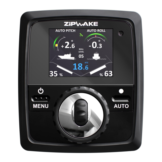
zipwake E Series Installation Manual
Dynamic trim control system
Hide thumbs
Also See for E Series:
- Operator's quick manual (2 pages) ,
- Start-up checklist (2 pages) ,
- Operator's manual (32 pages)
Table of Contents
Advertisement
Quick Links
Advertisement
Table of Contents

Summary of Contents for zipwake E Series
- Page 1 INSTALLATION GUIDE DYNAMIC TRIM CONTROL SYSTEM SERIES E...
-
Page 2: Mounting Options
E = 60 mm (2.4") I-BUS (Can Bus) Supply 12-32 V DC NOTE! Chine interceptor Up to six dual-servo Not Ok! interceptors or any mix with single-servo interceptors INTERCEPTORS INTERCEPTORS Copyright © 2021 Zipwake AB, Sweden. All rights reserved. R1B, January 2022, English... - Page 3 INTERCEPTOR INTERCEPTOR PREPARE THE TRANSOM PROPELLER CLEARANCE If the boat has an outboard engine or sterndrive, the interceptors must be ENSURE A FLAT SURFACE FOR EACH INTERCEPTOR mounted with clearance to the propeller(s). The transom must be relative- ly flat where the interceptors are mounted to ensure that they work properly.
- Page 4 INTERCEPTOR INTERCEPTOR INSTALL THE BACK PLATES 4A INSTALL THRU-HULL FITTINGS ABOVE THE WATERLINE A. FOR THRU-HULL FITTINGS ABOVE THE WATERLINE GO STRAIGHT TO STEP B. Mark the center of Drill holes (x4) for the cover base the thru-hull fitting Use the cover base as a drill template Slide out the cable Remove the Ø...
- Page 5 INTERCEPTOR INTERCEPTOR 4B INSTALL CONCEALED THRU-HULL FITTINGS UNDER THE WATERLINE NOTE! Slide back the cable plug and press down its cantilever Apply sealant Cable cover base: GRP hull: T25 (ST 4.8x25) Metal hull: Machine screws (not included) Fit the cable clip in the back plate NOTE! or cut it off...
-
Page 6: Distribution Unit
INTERCEPTOR DISTRIBUTION UNIT INSTALL THE INTERCEPTOR FRONTS MOUNT THE DISTRIBUTION UNIT Mount the distribution unit inboard where it is easy to connect it to both Interceptor front: interceptors and power supply (battery) e.g. the engine room or other T30 (PT 6.0x60) suitable compartment. -
Page 7: Route Cables
1. Pilot hole Ø 3 mm (1/8") Flybridge (optional) 2. Hole saw Ø 76 mm (3") Main control panel Flush mount option: refer to www.zipwake.com for a drawing and 3D model. Distribution Main bridge unit(s) Standard cable (15m) Extension cable... -
Page 8: Initial Start
Press and hold the POWER/MENU button until the INTERCEPTOR 400 E CHINE PORT SIDE IT400-E CHINE PORT 2012216 Zipwake logo appears on the display and follow WITH CABLE 3 M & CABLE COVER the steps on the screen. INTERCEPTOR 400 E CHINE STARBOARD SIDE... - Page 9 WIRING DIAGRAM WIRING DIAGRAM...
- Page 10 DU-E DU/INTERCEPTOR CONFIGURATIONS NOTE! Transom inside view STBD PORT DU-E DU-E DU-EX STBD PORT STBD PORT DU-EX DU-E DU-E DU-EX STBD PORT STBD PORT DU-E DU-EX DU-E STBD PORT STBD PORT DU-E DU-EX DU-E DU-EX STBD PORT STBD PORT DU-E DU-ED U-EX STBD...
- Page 11 Visit www.zipwake.com for additional information such as: • Operator’s Manual and Installation Guide in different languages • Product specifications, including a list of accessories and spare parts • Application examples and interceptor mounting options • Drawings and 3D models of system components •...


Need help?
Do you have a question about the E Series and is the answer not in the manual?
Questions and answers