
Related Manuals for LG CordZero A9 Series


Summary of Contents for LG CordZero A9 Series
- Page 1 LG Code Zero SVC Manual Caution : Please read the safety cautions of this booklet before checking theproduct. Buyer Model Name : A9****** Factory Model Name : VS97****** P.No MFL68043134 July, 2017 Printed in Korea...
-
Page 2: Table Of Contents
Content ■ Product features ......................3 ■ Parts and names .......................4 ■ Cleaner features .......................5 ■ Check these out before use ..................6 ■ Cautions for general usage ................7~12 ■ Technical descriptions of parts ................13 ■ How to use ......................14~19 ■... -
Page 3: Product Features
Rated DC 25.55 V , 1900 mAh Number of 7 ea. battery cells LG Chem (Battery pack manufactured Manufactured by TWS TECHNOLOGY (GUANGZHOU) LIMITED) 1) The suction power measurement standard is an average value measured by an independent testing institute by borrowing... -
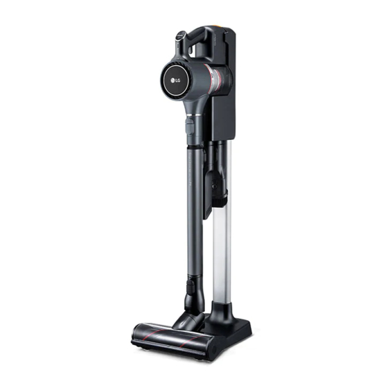
Page 4: Parts And Names
Parts and names Standing type Product body Extension pipe Charging station Adapter Charging station pipe 2-in-1, blade-shaped inlet holder Charging station support Adaptor Battery Wall type Body parts • Parts may vary depending on the specific model that you purchased. Blade shaped inlet Battery Inlet port for carpet... -
Page 5: Cleaner Features
Cleaner features 1. The product boasts of powerful suction that can be adjusted per purpose and site. The integrated inverter motor ensures consistent suction and you can adjust the suction strength depending on where you are cleaning. 2. Anti tangle power nozzle For cleaning ultrafine particles 3. -
Page 6: Check These Out Before Use
Please contact the customer service of LG Electronics if a same issue persists. • Any foreign object on the inlet port or exten- sion pipe will prevent the product from prop- er operation. -
Page 7: Cautions For General Usage
Cautions for general usage The following cautions intend to protect you from unexpected risk or property loss by ensuring safe and correct usage of the product. Cautions are categorized into ‘Warning’ and ‘Care’, which mean: The pictogram aims to remind you of matters and usage that may pose risks to the user. Make sure to carefully read the item with this symbol and comply with it to prevent any potential risk. - Page 8 Please stop using the AC 220V only. Make sure to product and contact the check the power specifica- AC 110V customer service of LG Elec- tions of the place to use the tronics upon finding that product. the power cord or power •...
- Page 9 • • It•may•damage•the•prod- station. uct•and/or•injure•people. • • Otherwise,•you•may•get• injured•or•suffer•electric• No one other than a shock. qualified technician/ service engineer from LG Do not apply or spray Electronics may disas- flammable substance(- semble, repair or modify gasoline or thinner) or Gasoline the product.
- Page 10 LG Electronics. Never allow any water, bev- • • It•may•cause•electric•shock• erage or detergent to get or•fire. inside of the battery. Do not expose the product, •...
- Page 11 • • It•may•cause•fire•or•explo- remove the product from sion. the station and contact the customer service of LG Electronics. • • It•may•cause•electric•shock• or•fire. Do not wash the dust bin with water. • • The•water•will•get•into•the•...
- Page 12 Cautions for general usage Care Proper usage Do not apply shock to the Do not put any object other product or drop it from than the product, especial- height. ly a metallic or magnetic object, on the charging • • It•may•damage•the•product• station.
-
Page 13: Technical Descriptions Of Parts
Technical descriptions of parts Model Item VS97****** Category Integrated motor Power DC 25.55V Power consumption 400 W (MAX : 450 W) R. P. M 115000 R.P.M Lifecycle More than 205 hours -13-... -
Page 14: How To Use
Environmental conditions such as temperature and hu- • midity may cause static on the product. Please contact the customer service of LG Electronics if a same issue persists. Extension pipe Any foreign object on the inlet port or extension pipe length button •... - Page 15 How to use Charging the product Put the battery in the auxiliary charging station. Put the product in the charging station. The battery indicator starts to flash and charging • will start in 3 steps. 보조 배터리 충전 지시등 Charging indicator of the auxiliary battery The battery indicator starts to flash and charging Please note...
- Page 16 How to use Using inlet port 2 in 1 inlet port The accessory inlet port is helpful for cleaning a corner or Please note that the following are applied to the corre- • small gap. sponding models: The inlet can be attached to the product body or the •...
- Page 17 How to use Cleaning the dust bin Remove the dust separation device and use the 2-in-1 inlet port to clear the dust inside the dust Remove the battery from the product before bin. cleaning. Please move close to a wastebasket or where dust/foreign object can be emptied easily.
- Page 18 How to use Brush dust off from the exhaust filter. Warning Make sure to clean the exhaust filter every • Never wash the product’s body with water. Water may • month to ensure optimal cleaning performance. reach the motor and cause electric shock or fire. Make sure that no foreign object reaches the motor.
- Page 19 How to use Cleaning floor/carpet inlets Care Avoid getting your finger stuck in a gap. • Please clean the floor and carpet inlets as follows: Do not wash the rotating brush and the inlet port with • Remove the inlet from the product. water.
-
Page 20: Disassembly, Assembly And Repairing Of Main Parts
Disassembly, assembly and repairing of main parts Cautions for disassembling ▶ Make sure to remove the batteries before disassembling the product. 1. Most parts are screwed in or inserted mutually. Please refer to theexploded diagram to disassem- ble the product in the correctsequence. 2. - Page 21 Disassembly, assembly and repairing of main parts 2. Replacing main PCB (2) Remove the button with (3) Disassemble Screw in the (1) Disassemble the handy a knife or a sharp object. button. part from the product body. Use a thick pieceof paper in-between to protect the surface of the part, which willhave to replaced if...
- Page 22 Disassembly, assembly and repairing of main parts 3. How to replace motor assembly (2) Pull the pipe part with a (3) Remove the screws on the (1) Disassemble the decora- hand. bottom of the pipe. tion part with a flat head- ed screwdriver.
- Page 23 Disassembly, assembly and repairing of main parts 4. Disassembling the inlet roller(floor inlet) (2) Push the left bump up (3) Use a long phillips (1) Remove the inlet lever with and remove the roller to screwdriver to remove the a coin. screw in the center.
- Page 24 Disassembly, assembly and repairing of main parts 5. How to disassemble the inlet motor(floor inlet) (3) Remove 4 screws in the (2) Remove the cover of the (1) Disassemble the inlet red circle. right bump with a hand. roller (Refer to how to disassemble the inletroller in details) (4) Remove the cover below...
- Page 25 Disassembly, assembly and repairing of main parts 6. Removing charging station PCB (3) Remove the base cover (2) Remove the screw from (1) Loosen the 3 screws from after removing the screw. the groove in the red circle. the base. (4) Inside of the charging (5) Remove the terminals of (6) Remove the bump inside...
- Page 26 Disassembly, assembly and repairing of main parts 7. Disassembling handy decoration assay (3) Hold and pull the (2) Apply the same method (1) Use a flat headed screw- decoration assay with a to other parts to open the driver to insert the inner hand.
-
Page 27: Cautions And What To Check For Repairing
Cautions and what to check for repairing 1. Make sure to remove the batteries first and unplug the chargingstation when checking or repairing the product. 2. Make sure that no metallic object gets in contact with the chargingterminal when checking the current of the circuit. 3. -
Page 28: Circuit Diagram
Circuit diagram • Station PCB -28-... - Page 29 Circuit diagram • Main PCB(Power) -29-...
- Page 30 Circuit diagram • Micom -30-...
- Page 31 Circuit diagram • Inverter -31-...
-
Page 32: Symptoms Of Malfunctions And Measures
Symptoms of malfunctions and measures Symptoms of Inspection result Cause Measures malfunction Pressing the Product is Make sure Bad connection Pressing the power button malfunctioning that all parts power button does not start are connected Product is not does not start the motor of the correctly. - Page 33 Symptoms of malfunctions and measures Symptoms of Inspection Cause Measures malfunction Remove the foreign object. Impeller has a foreign object on it. Rotation is slow. Battery charges too slowly. Charge the battery. Set the suction button at Suction button is set at Suction is too "Turbo"...
-
Page 34: Cleaning Functions And Error Modes
Cleaning functions and error modes Symptoms Causes How to check Measures No power engaged Main PCB is defective. Check if the main PCB has 5V Replace the main PCB. (Pressing the power button and 12V power. Replace the battery if the does not lead to anyfunction) Check if the battery has charging station has no... -
Page 35: Exploded Diagram
#EV# Exploded diagram VS97****** ◎ Flufy Nozzle Assembly AGB01 MCK001 MCR401 AHR701 MCK6101 MCR501 EAU301 -35-... - Page 36 #EV# Exploded diagram VS97****** ◎ Handle Assembly ADQ901 ADQ001 EBR101 MBG101 EBR001 MCR601 EAU703 EBR901 MGJ101 AED401 MEK701 MGE801 ACW201 MCK201 MCK101 ADV701 MCR801 AGU501 MJM801 MFC801 AJL001 -36-...
- Page 37 #EV# Exploded diagram VS97****** ◎ Base Assembly Body EBR801 AAN701 AAN701 -37-...
- Page 38 #EV# Exploded diagram VS97****** ◎ Base Assembly, Lower AAN801 -38-...
- Page 39 #EV# Exploded diagram VS97****** ◎ Assessories AEJ701 ABC901 AGB401 ABCAD3 AGBNU1 ◎ Pipe Assembly AGR201 AGR301 -39-...
- Page 40 #EV# Exploded diagram VS97****** ◎ Battery EAC201 ◎ Adaptor EAY401 -40-...
- Page 41 #EV# Exploded diagram VS97****** ◎ Power Punch Nozzle AGB403 -41-...
- Page 42 #EV# Exploded diagram VS97****** ◎ Carpet Nozzle AGB402 AHR702 EAD902 -42-...
Need help?
Do you have a question about the CordZero A9 Series and is the answer not in the manual?
Questions and answers