Table of Contents
Advertisement
Quick Links
USB PD Controller Series
Stand-Alone PD Controller for Sink
BD93E11GWL EVK
BD93E11GWL-EVK-001 (Stand-Alone)
Introduction
The User's Guide describes the series of required procedures to operate and evaluate the EVK of the PD controller BD93E11GWL
for Sink. The document also contains the circuit components, the operating procedures, and the Application Data.
Overview
BD93E11GWL-EVK-001 implements Stand-Alone PD Controller IC of BD93E11GWL in Sink mode. This EVK performs the Type-
C connection and make PD contracts with the attached Source device according to the configuration of the DIP switches on the
board. The EVK assumes Stand-Alone operation in the Dead Battery mode, so this EVK does not need an external power source
and works as a VBUS powered product. The board will supply power and voltage via VSNK terminal based on the negotiation
contracted with the source. Therefore, any existing board that is powered by an AC adapter or a regulated power supply up to
80W/20V can work and be evaluated with the EVK as a Type-C/PD power source.
EVK Operation Condition
Parameter
VBUS Power Supply
VSRC5V Power Supply
VSNK Output Voltage
VSNK Output Current Range
© 2021 ROHM Co., Ltd.
Min
Typ
Max
3.67
5.0
3.1
5.0
5.5
4.75
5.0
3.0/5.0
1/18
User's Guide
Units
22
V
V
Guaranteed by USB Standard and
22
V
connected Source.
Depending on the Type-C cable. The
actual load current is depending on the
A
sink device operation that connects to
VSNK terminal.
Conditions
No. 64UG056E Rev.001
2021.10
Advertisement
Table of Contents

Related Manuals for Rohm BD93E11GWL-EVK-001


Summary of Contents for Rohm BD93E11GWL-EVK-001
- Page 1 Sink. The document also contains the circuit components, the operating procedures, and the Application Data. Overview BD93E11GWL-EVK-001 implements Stand-Alone PD Controller IC of BD93E11GWL in Sink mode. This EVK performs the Type- C connection and make PD contracts with the attached Source device according to the configuration of the DIP switches on the board.
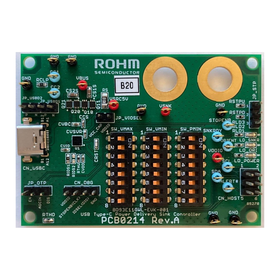
- Page 2 Figure 1. BD93E11GWL-EVK-001(Top View) Descriptions of EVK function Figure 2. The descriptions of the part of BD93E11GWL-EVK-001 This EVK has the functions that are defined in Table 1. Other than the functions listed, this EVK User Guide does not support it.
- Page 3 Communication terminal for USB 1.x / 2.0 D+(P)/D-(N) USB 1.x / 2.0 JP_USBD1, JP_USBD1: CC1 side communication JP_USBD2 JP_USBD2: CC2 side We cannot respond to inquiries other than the functions above. © 2021 ROHM Co., Ltd. No. 64UG056E Rev.001 3/18 2021.10...
- Page 4 BD93E11GWL-EVK-001 (Stand-Alone) User’s Guide EVK schematic Figure 3. BD93E11GWL-EVK-001 Schematic © 2021 ROHM Co., Ltd. No. 64UG056E Rev.001 4/18 2021.10...
-
Page 5: Operating Sequence
Set SW_VMAX, SW_VMIN and SW_PMIN according to required PD contract. Please refer to Figure 9 for further information. When connecting the existing system board for evaluation, connect the EVK into the existing system board before power up as shown in Figure 6. © 2021 ROHM Co., Ltd. No. 64UG056E Rev.001 5/18... -
Page 6: Digital Multimeter
USB Digital default. Therefore, a PD Multimeter BD93E11GWL-EVK-001 contract cannot accomplish, and the device connects by Type-C. Figure 5. An example of the connection with Type-A to C Cable © 2021 ROHM Co., Ltd. No. 64UG056E Rev.001 6/18 2021.10... - Page 7 Figure 7. An example of USB connection on an existing system board USB PD Protocol Analyzer Type-C Cable Type-C Wall Charger BD93E11GWL-EVK-001 Figure 8. An example of the connection with a protocol analyzer for PD communication © 2021 ROHM Co., Ltd. No. 64UG056E Rev.001 7/18 2021.10...
- Page 8 Change SW_VMAX, SW_VMIN, and SW_PMIN according to the requirement. Power up VSRC5V if necessary. The new configuration is stored at power up. Reconnect the Source device to the Type-C receptacle of the EVK via the Type-C cable. © 2021 ROHM Co., Ltd. No. 64UG056E Rev.001 8/18...
- Page 9 ·If a setting where SW_PMIN / min (SW_VMAX or SW_VMIN), exceeds 5A, then It will operate as 5V@0.1A. Figure 9 shows the specific range by SW_VMAX, SW_VMIN, and SW_PMIN that allows USB PD Contract. © 2021 ROHM Co., Ltd. No. 64UG056E Rev.001 9/18 2021.10...
- Page 10 For example, if the EVK that SW_VMAX is set to 12V and connected to the Source device specified in Figure 10 where the Source device does not have 12V as an option, then the contract with the EVK will be PDO of 9V@3A. © 2021 ROHM Co., Ltd. No. 64UG056E Rev.001 10/18 2021.10...
- Page 11 Table 4. The parameters of the OTP with PTC thermistor Items Detection temperature [°C] Implemented PTC thermistor MURATA PRF15BD102QB6RC as RTHU ON Threshold [V] 0.780 OFF Threshold [V] 0.470 Divided resistance RTHU [Ω] Figure 11. OTP Schematic Circuit © 2021 ROHM Co., Ltd. No. 64UG056E Rev.001 11/18 2021.10...
-
Page 12: Parts List
MAC 8 LC-2-G-White TESTPIN TP11, TP12 TPGND1, TPGND2, SGND MAC 8 LC-2-G-Black TESTPIN TPGND3 TPGND4 TPGND5 MAC 8 LC-2-G-Black TESTPIN TPGND6 TPGND7 TERMINAL VSNK Not Mount TESTPIN TERMINAL Not Mount TESTPIN © 2021 ROHM Co., Ltd. No. 64UG056E Rev.001 12/18 2021.10... - Page 13 Model Number [mm(inch)] ADAM TECH PH2-06-UA CN_HOST HDR2X3 HDR2X3 ADAM TECH PH1-04-UA CN_DBG HDR1X4 HDR1X4 ADAM TECH PH1-03-UA JP_STP, JP_OTP HDR1X3 HDR1X3 JP_VIOSEL JP_USBD1 ADAM TECH PH1-02-UA HDR1X2 HDR1X2 JP_USBD2 © 2021 ROHM Co., Ltd. No. 64UG056E Rev.001 13/18 2021.10...
-
Page 14: Board Layout
EVK PCB Information Number of Layers Material Board Size Copper Thickness FR-4 70mm x 50mm x 1.6mmt 1oz (35μm) Figure 12. Top Layer (Top View) Figure 13. Middle Layer 1 (Top View) © 2021 ROHM Co., Ltd. No. 64UG056E Rev.001 14/18 2021.10... - Page 15 BD93E11GWL-EVK-001 (Stand-Alone) User’s Guide Figure 14. Middle Layer 2 (Top View) Figure 15. Bottom Layer (Top View) © 2021 ROHM Co., Ltd. No. 64UG056E Rev.001 15/18 2021.10...
- Page 16 Turn on FET(Q20,Q21) by PD Source contract completion then Accept PS_RDY Capability Request VBUS is supplied to VSNK Figure 17. The Waveform of the USB PD Negotiation at 20V (Detailed PD Communication) © 2021 ROHM Co., Ltd. No. 64UG056E Rev.001 16/18 2021.10...
- Page 17 USB PD system. Below are some relatively inexpensive protocol analyzers that have enough merits in the USB IF workshop. ⚫ Total Phase USB Power Delivery Analyzer TP350110 ⚫ TELEDYNE LECROY Mercury T2C Protocol Analyzer USB-TMPD-M02-X © 2021 ROHM Co., Ltd. No. 64UG056E Rev.001 17/18 2021.10...
-
Page 18: Revision History
BD93E11GWL-EVK-001 (Stand-Alone) User’s Guide Revision History Revision Date Description Number Oct. 19. 2021 Initial release © 2021 ROHM Co., Ltd. No. 64UG056E Rev.001 18/18 2021.10... - Page 19 Products. ROHM does not grant you, explicitly or implicitly, any license to use or exercise intellectual property or other rights held by ROHM or any other parties. ROHM shall have no responsibility whatsoever for any dispute arising out of the use of such technical information.
Need help?
Do you have a question about the BD93E11GWL-EVK-001 and is the answer not in the manual?
Questions and answers