Advertisement
Quick Links
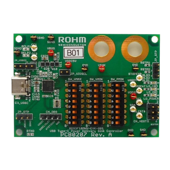
USB Type-C Power Delivery Controller
BD93F10MWV Function Description
This device is a USB Type-C controller that implements USBPD3.0 (USB Power Delivery rev.3.0 Ver1.2) for an end product that is required to
sink power (referred to as a SNK / UFP (Sink / Upstream Facing Port)). These devices are intended to operate in stand-alone mode with no
configuration or control required from the product's SoC. The intended application is for products that are connected to an external USB-PD
power source device. These devices perform USB-PD negotiations to communicate the necessary and desired voltage and power
requirements with the power source, and assures that the correct voltage and power is provided or it will not allow power into the product.
These devices can be used in products that require up to 80W (20V/4A) of delivered power. Using these devices allow the product designer to
allow for powering their device over USB, whereas previously a separate power input had to be provided.
Specifications Description
The product automatically performs the operations required for
USBPD3.0 due to complete FW. After power up, the product pulls
down the CC (Configuration Channel) terminal and enters standby
state. During this state, when a Source device is connected, the Type-
C connection is determined, then it enters the Active (Type-C) state.
CC terminals are then used to communicate with USBPD in the
following sequence: As the "Source Capabilities" comes from the
Source side, the product returns a "Request" according the initial
configuration which is specified below. Next, the Source sends an
"Accept" and "PS_RDY" respectively, and connects (makes a
contract) as USBPD, then transitions to Active (USBPD) state which
operates as SNK / UFP. In the case where the Source device does
not support USBPD, it remains in the Active (Type-C) state and
operates as SNK / UFP.
Remove a connection
from a source and
VSVR lost, or
During a connection
with a source and
VSVR lost.
Remove a connection
from a source and
VSVR is being applied.
Source
Source
Capabilities
BD93F10 in
a product
product
Request
Source
BD93F10 in
product
a product
Accept
Source
BD93F10 in
a product
product
PS_RDY
Source
BD93F10 in
a product
product
Figure 1. Operation modes of BD93F10MWV
© 2021 ROHM Co., Ltd.
Shutdown
(Dead Battery)
Connecting to a
source, or VSVR is
being applied.
HW Stand-by
Initialization
Complete a boot
sequence
Wait
Complete Type-C
connection detection after
Source is connected.
Active
(Type-C)
A source has supported
USBPD, and USBPD
communication is completed
Active
(PD)
1/13
Application Note
After contracting (receiving PS_RDY) to the specified power, the Nch-
MOS switch on the VBUS power line is controlled, where it
automatically starts receiving power. Therefore, stand-alone
operation is possible even without the control from Host.
The product can support Dead Battery operation by utilizing the
voltage of the VBUS power line. Therefore, it can still operate even if
the internal power of the system has lost completely.
The Nch-MOS switch on the VBUS Power turns off automatically
when it is disconnected to the Source device.
[Power Supply specification]
●VBUS Voltage = 3.67 to 22V
●VSVR = 3.1 to 5.5V
●VDDIO = 1.7 to 5.5V
[Type-C initial Connection specification]
●SNK / UFP
[SRC (Power Source) specification]
Disabled
[SNK (Power Sink) specification]
Dependent on VMIN / VMAX / PMIN setting of the GPIO
[Role Swap initial specification]
●Power Role Swap to SNK : Disabled
●Power Role Swap to SRC : Disabled
●Data Role Swap to DFP (Downstream Facing Port) : Disabled
●Data Role Swap to UFP : Disabled
No. 64AN078E Rev.002
Nov.2021
Advertisement

Related Manuals for Rohm BD93F10MWV


Summary of Contents for Rohm BD93F10MWV
- Page 1 (PD) Source BD93F10 in a product product ●Data Role Swap to DFP (Downstream Facing Port) : Disabled Figure 1. Operation modes of BD93F10MWV ●Data Role Swap to UFP : Disabled © 2021 ROHM Co., Ltd. No. 64AN078E Rev.002 1/13 Nov.2021...
- Page 2 The product is on stand-alone and does not use this function. GPIO9/SCL1 VBRDY “O”:VDDIO Level Output “N-OD”:Nch Open Drain Output Unused terminal is Hi-Z. Please use Open or Pull down to GND. © 2021 ROHM Co., Ltd. No. 64AN078E Rev.002 2/13 Nov.2021...
- Page 3 Throughout the transition, reset would not be triggered, maintaining the Type-C connection. If power is supplied to VB terminal only, the product’s behavior is similar to Dead Battery operation. © 2021 ROHM Co., Ltd. No. 64AN078E Rev.002 3/13 Nov.2021...
- Page 4 Initialization Wait Operation (Type-C) (PD) NOTE: BD93F10MWV can only support Type-C and USB PD Type-C detection completion standards and NOT support any proprietary charging According to USB Type-C/PD Spec. methods including DCP and CDP in BC1.2. These are Figure 4. Timing Chart for Normal Operation...
- Page 5 (OTP function: Over Temperature Protection) in the system by using an external thermistor RTHD (PTC Thermistor). For example, the system can monitor the thermal condition via the OTP by implementing a PTC © 2021 ROHM Co., Ltd. No. 64AN078E Rev.002 5/13 Nov.2021...
- Page 6 Nch-MOS switch on the VBUS power line is turned off to isolate the system from Type-C receptacle safely. Please see Table 9 for more details regarding the behavior after the © 2021 ROHM Co., Ltd. No. 64AN078E Rev.002 6/13...
- Page 7 GPIOs after bootup. Figure 9. CC2 Connection of SNK / UFP And also refer to the BD93F10MWV Datasheet regarding the electrical characteristic of the inputs and outputs. Table 5. Timing characteristic of asserting ORIENT ●Unused (GPIO0, GPIO1)
- Page 8 This product requests and negotiates a PDO that does not Figure 13. Example of the contract with a 15W source device exceed the maximum current from the required voltage / © 2021 ROHM Co., Ltd. No. 64AN078E Rev.002 8/13 Nov.2021...
- Page 9 Connectable Power Range (Nch-MOS is Limitation by turned on) 3A Cable PMIN =60W Source supports 100W 5V,9V,15V,20V Voltage[V] VMAX VMIN Figure 15 Contract with 100W Source device via 3A cable © 2021 ROHM Co., Ltd. No. 64AN078E Rev.002 9/13 Nov.2021...
- Page 10 1.0 μ F SGND 10 mΩ SGND Internal System use to GND . Figure 17. The Recommended Application Example for Stand-Alone Operation (VBUS OCP: Available, OTP with PTC thermistor: Disabled) © 2021 ROHM Co., Ltd. No. 64AN078E Rev.002 10/13 Nov.2021...
- Page 11 NOT required. Please select the thermistor which can be detected with expected temperature. *The back-to-back architecture is composed by Q20 and Q21. And these parts have been complied with the official USB PD certification. © 2021 ROHM Co., Ltd. No. 64AN078E Rev.002 11/13 Nov.2021...
- Page 12 <- Sleep Mode Stop Mode (When Type-C plug connect, Low power mode), depend <- Enable on STOPENB (GPIO4) *1 “<-” shows that it does the Behavior same as the Value © 2021 ROHM Co., Ltd. No. 64AN078E Rev.002 12/13 Nov.2021...
- Page 13 BD93F10MWV Function Description Application Note Revision History Revision Date Description Number Sep. 8. 2021 Initial Release Nov. 8. 2021 Added Captions on PDF. © 2021 ROHM Co., Ltd. No. 64AN078E Rev.002 13/13 Nov.2021...
- Page 14 Products. ROHM does not grant you, explicitly or implicitly, any license to use or exercise intellectual property or other rights held by ROHM or any other parties. ROHM shall have no responsibility whatsoever for any dispute arising out of the use of such technical information.
Need help?
Do you have a question about the BD93F10MWV and is the answer not in the manual?
Questions and answers