Table of Contents
Advertisement
Quick Links
Advertisement
Table of Contents

Related Manuals for ORBOT Pacific Floorcare MSE-19 ORB


Summary of Contents for ORBOT Pacific Floorcare MSE-19 ORB
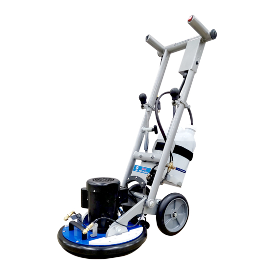
- Page 1 Powered by MSE - 19 ORB OPERATING MANUAL 2022...
-
Page 2: Machine Data
MACHINE DATA MSE-19 ORB MACHINE DATA MSE-19 ORB Model: Serial: Date of Purchase: Dealer: Address: Phone Number: Sales Representative:... -
Page 3: Table Of Contents
TABLE OF CONTENTS Machine Data How to Use This Manual Safety - Important Instructions 5 - 7 Technical Details 9 - 16 Operation Unpacking and Initial Operations Pre-Run Inspection Power Cable Connection Spray System Preparation Spray Jets Adjusting Height Process of Cleaning End of Application Storage Lifting and Carrying... -
Page 4: How To Use This Manual
HOW TO USE THIS MANUAL This manual contains the following sections: • How to Use This Manual The PARTS LIST section contains assembled parts illustrations and corresponding parts • Safety list. The parts lists include a number of • Operations columns of information: •... -
Page 5: Safety - Important Instructions
SAFETY IMPORTANT SAFETY INSTRUCTIONS When using this machine, basic precautions must always be followed, including the following: READ ALL INSTRUCTIONS BEFORE USING THIS MACHINE. WARNING To reduce the risk of fire, electric shock, or injury: • Use only indoors. Do not use outdoors or expose to rain. •... - Page 6 SAFETY The following symbols are used throughout this guide as indicated in their descriptions: HAZARD INTENSITY LEVEL There are three levels of hazard intensity identified by signal words -WARNING, CAUTION, and FOR SAFETY. The level of hazard intensity is determined by the following definitions: WARNING WARNING - Hazards or unsafe practices CAN result in severe personal injury or death.
- Page 7 SAFETY GROUNDING INSTRUCTIONS 120V THIS PRODUCT IS FOR COMMERCIAL USE ONLY ELECTRICAL: In USA this machine operates on a 15 amp nominal 120V, 60 hz, A.C. power circuit. The amp, hertz, and voltage are listed on the data label found on each machine.
-
Page 8: Technical Details
TECHNICAL DETAILS ITEM SPECIFICATIONS Motor 1HP, 1400W, 6-12amp, 100-240V, 50/60Hz Dual Speed 1725 RPM (Orbital), 80 RPM (Rotational) Drive Diameter 19” (48.26 cm) Wheel Diameter 10” (25.4 cm) Quick-Connect Power Cord 50 ft. (15m) Solution Tank Capacity 3 Gallon (11.4L) Pump 90 PSI (6.2 BAR) Noise Level... -
Page 9: Operation
Unpacking and Initial Operations OPERATION Open shipping box (both sides). Remove packaging material and roll machine out of box. Pre-Run Inspection Before each use, inspect for cracks, tears or excess wear. If the machine or accessory is dropped, inspect for damage. Then repair or replace, if necessary, before use. -
Page 10: Spray Jets
OPERATION Spray Jets Adjust spray jets on machine base to the desired position. For most floor cleaning applications, adjust spray jets so they spray about 6 inches (15 cm) in front of the base. Adjusting Height Set handle position to desired height by pulling and releasing the black knob with the left hand. -
Page 11: End Of Application
OPERATION End of the Application Turn off the machine by putting the on/off switch to “O”. If a cleaning solution was used, fill bottle cartridge with water and spray out system for 30 seconds. Make sure to not let solution come in contact with the motor. Storage To avoid damage to the handle frame, do NOT lay machine frame on floor as done with... -
Page 12: Weight Kit Installation
OPERATION Weight Kit Installation Place the weight kit (40 lbs.) on top of the mounting plates located on the sides of the machine base. Put the 4 screws into the holes provided on the weight plates and fasten by turning clockwise. -
Page 13: Attaching And Removing The Driver Plates
OPERATION Attaching and Removing the Driver Plates Put the machine base in an upright position, sitting on the foot of the bumper. Remove the driver plate by removing the four countersink screws in the center of the plate using an electric screwdriver. Attach a driver plate to the machine base by lining up the holes of the driver plate with the appropriate threads of the bearing retainer... -
Page 14: Multi-Floor Velcro Driver Plate
OPERATION Multi-Floor Velcro Driver Plate Exclusively use designated driver plates only. Using other driver plates will damage the machine and its mechanical action. Driver plates are fastened on the machine base with four countersink screws. The 19” driver plate supplied is suitable for all pads on textile and hard floor applications. -
Page 15: Ultralift Pad
OPERATION UltraLift Pad The UltraLift pad can be used on stone, concrete, VCT, marble and porous surfaces. Each pad can clean an approximate area of 4,000 sq. ft. (372m²) depending on floor type and level of soil. AkwaStrip Pad The AkwaStrip pad is a chemical free stripping pad made of a unique material filled with diamonds. -
Page 16: Multi-Purpose Scrub Brush
OPERATION Multi-Purpose Scrub Brush The bristles of the brush are made of high quality nylon. The unique brush design is ideal for cleaning tile and grout, smooth concrete, rubber flooring and other microporous surfaces such as porcelain and safety tiles. It can also be used for any other hard surfaces. -
Page 17: Operation/Maintenance (Application On Different Floors)
OPERATION / MAINTENANCE APPLICATION ON DIFFERENT FLOORS Carpet Cleaning Vacuum the carpet thoroughly before cleaning. Large dirt particles are removed, allowing the application to be more effective. Apply solution while moving forward. Clean by going forward and backwards 2 to 3 times, while applying solution on the first pass in order to keep the drying time low. -
Page 18: Part Diagrams And Part Lists
PARTS HANDLE ADJUSTMENT ASSEMBLY ITEM NO PART NUMBER QTY DESCRIPTION 570151 ROD, HANDLE 570149 PULL LATCH BODY 570150 PULL LATCH 570037 SHAFT COLLAR 570129 SCREW, 1/2-13 X 2" 570152 WASHER, NYLON, 1/2" 570132 HEX NUT, LOCK, .5-13 X .75W X .312 570129 SCREW, 1/2-13 X 2"... - Page 19 PARTS SOLUTION TANK & CAGE ASSEMBLY ITEM NO PART NUMBER QTY DESCRIPTION 570065 / 570156 1/1 BOTTLE CARTRIDGE, 3-GALLON / CAGE ASSY 570179/ 570174 BOTTLE CAP ASSY/ VELCRO STRAP, 2” X 36” 570171/570059 1/4 PUMP, (DOMESTIC)/SCREW, 6-32 X 1-1/4” 570060/570061 4/4 WASHER, PUMP MOUNT / HEX NUT, 6-32, NYLOCK 570182 STOP, CAGE/MOTOR...
- Page 20 PARTS MOTOR & BASE ASSEMBLY ITEM NO PART NUMBER QTY DESCRIPTION 570184 BASE, .1875 THK 570075 BUMPER, 19” 570120 WEIGHT PLATE ASSEMBLY 570078 HANDLE, BASE 570185 SCREW, 1/4-20 X 1-1/2" 570119 NUT, 1/4-20 X 5/16, TEE, 4 PRONG 570114 SCREW, 3/8-16 X 3/4" 570115 WASHER, FLAT .38 ID X 1 OD X .06THK 570076...
- Page 21 PARTS WHEEL KIT ASSEMBLY ITEM NO PART NUMBER QTY DESCRIPTION 5701283 WHEEL, 10” 570199 ROD, WHEEL 3 - 1 570080 LEFT EAR, WITH PIN 3 - 2 570081 RIGHT EAR, WITH PIN 570200 SCREW, .5-13 X 3-3/4" 570131 WASHER, PLASTIC, .5 ID X 1.125 OD X .125 THK 570114 SCREW, HEX HEAD, 3/8-16 X 3/4"...
- Page 22 PARTS LOWER HANDLE / FRAME ASSEMBLY ITEM NO PART NUMBER QTY DESCRIPTION 570019 HANDLE ASSY, LOWER 570027 KNOB, LOCKING POSITION 570028 “T” SCREW, KNOB, HANDLE 570026 SCREW, 1/4”-20 X 1.5”, LOWER HINGE 570129 SCREW, .5-13 X 2” 570131 WASHER, PLASTIC, .5 ID X 1.125 OD X .125 THK 570132 HEX NUT, LOCK, .5-13 X .75W X .312 570198...
- Page 23 PARTS UPPER HANDLE / FRAME ASSEMBLY ITEM NO PART NUMBER QTY DESCRIPTION 570019 HANDLE ASSY, UPPER, W/ELECTRICAL BOX 570193 HARNESS, MAIN HANDLE, 7 CONDUCTOR 570030 SWITCH, ROCKER, SPRAYER, DOUBLE POLE 570144 HARNESS, SPRAYER SWITCH 570029 SWITCH, ROCKER , ON/OFF, DOUBLE POLE 570143 HARNESS, ON/OFF SWITCH 570146...
- Page 24 PARTS MOTOR ASSEMBLY ITEM NO PART NUMBER QTY DESCRIPTION 570102 SCREW, FAN COVER, 10-32 X 3/8” 570101 COVER, MOTOR FAN 570100 FAN, MOTOR 570110 LOCK NUT, 1”, ELECTRICAL BOX 570191 SCREW, MOTOR LID 570112 CORD, BLUE PLUG, 100-120V, PUMP 570113 CORD, BLACK PLUG, 100-120V, AUX 570111 CORD GRIP, 1”, ELECTRICAL BOX...
- Page 25 PARTS SPRAY NOZZLE ASSEMBLY ITEM NO PART NUMBER QTY DESCRIPTION 570092 QUICK CONNECT, 1/4”, TEE, SPRAY NOZZLE 570095 ELBOW, 1/4”, 90°, SPRAY NOZZLE 570096 HOSE, SPRAY JET 570097 T-HOSE, SPRAYJET 570082 L-BRACKET, NOZZLE BASE 6 - 1 570083 SPRAY BRACKET, TOP LEFT 6 - 2 570084 SPRAY BRACKET, TOP RIGHT...
- Page 26 PARTS DISC DRIVER ASSEMBLY ITEM NO PART NUMBER DESCRIPTION 570316 DRIVER, DISC, 19” 570315 RING, MULTI-FLOOR DRIVER, 19” 570105 COUNTER WEIGHT ASSY, w/BEARING 570104 SHAFT SUPPORT 570106 SCREW, 1/4-20 X 3/4” 570121 SCREW, 1/4-20 X 1" 576601 PAD, VELCRO 570118 SCREW, 1/4-20 X 3/8"...
-
Page 27: Wiring Diagram
WIRING DIAGRAM... - Page 28 Powered by 2259 Sheridan Drive, Muskegon, MI 49442, USA P: 800-968-1332 | orders@PacificFloorcare.com www.PacificFloorcare.com PURPOSE BUILT to CLEAN FLOOR!
Need help?
Do you have a question about the Pacific Floorcare MSE-19 ORB and is the answer not in the manual?
Questions and answers